
 ?Mathematical formulae have been encoded as MathML and are displayed in this HTML version using MathJax in order to improve their display. Uncheck the box to turn MathJax off. This feature requires Javascript. Click on a formula to zoom.
Abstract
Visual performance and visual comfort are a combined effect of the illumination characteristics and the illuminated objects. Current surgical lighting systems have a fixed shape illumination pattern, whereas the wound and surroundings have a variable shape and characteristics. A lighting system that is able to adapt its shape and light distribution to the characteristics of the wound might improve visual performance. This paper describes the development of a new concept for lighting using bendable strips with LEDs. The basic idea of placing LEDs on a bendable surface is very simple and elegant. To achieve a functional system, the effects of the different design choices, such as shape of the strips, number of LEDs, number of strips, and LED power were investigated. The influence of these choices is evaluated by simulation using a computational model to identify the optimal parameters for the design. The final design is evaluated using the computational model and a physical prototype consisting of one luminaire segment. The system is able to produce light fields that can have fairly complex shapes at a good range of different sizes. Recommendations about aspects like spot size and strip number are given. The physical test model indicates that the calculated system functions close to how it would in a real-life situation. Given the results, it expected that a system, which is able to modify the light field in real time and that requires minimal control effort, could improve lighting in the operating room.
1. Introduction
Proper lighting is an essential factor during a surgical procedure [Citation1–5]. Many different luminaire systems are available on the market that all provide lighting in a generally comparable manner [Citation6–9]. These current surgical luminaire systems often consist of a large central light source, sometimes accompanied by one or two satellite light sources and they are manually moved into position. These systems are able to project light towards the surgical field. The shape of the projected light field is determined by the luminaire output of the system, the shape of the illuminated surface and the orientation that the luminaire and the target surface have in relation to each other. One set of parameters that control the properties of the projected light field is determined by the suspension arm system by which the luminaire is connected to the ceiling. The range of motion of the suspension system determines under which angles the light is able to be projected and what the distance of the light source can be to the surgical area. Another set of parameters is determined by the light source itself. Typical properties of the light source are; the surface area of the light emitting surface, the shape of that surface, the focus point of the light beam, shape of the beam, spectral bandwidth and many more. These properties of the light source determine the shape and light distribution of projected light field and luminance of the illuminated surface.
Vision is a complex and dynamic sensory function. How well a person can see is largely determined by the lighting conditions that affect the illuminated object. Current surgical lighting systems project a round light field onto the surgical field that has a more or less a circular Gaussian distribution. As wounds are often not round in shape, it is thought that a circular distribution is in many circumstances not the optimal lighting condition. Visual discomfort might arise from the fact that unnecessary areas inside the operating field are being illuminated. Everybody has experienced the effect of trying to look at a dark region when there is brightly illuminated region in front of it. It is difficult to see until you block the bright region, e.g., with your hand. This effect is also applicable to the situation in the operating room [Citation10,Citation11]. Even though complete blinding might not occur, the situation is often far from optimal. Surgical drapes have reflective properties of 35%, whereas the reflective properties of the wound area are around 8% [Citation11]. This creates a ratio of 4.3:1 which is larger than the recommended ratio below 3:1. The solution that the surgeon has to compensate for this, is to manipulate the luminaire during surgical procedures to redirect the light away from the high intensity areas, or cover high reflecting surfaces.
A light field that is able to adapt its shape according to wound dimensions might provide a better lighting condition and thereby decreasing visual strain and increasing the performance of the surgeon. The main goal of this study is to design a system that is able to provide greater adaptability of the light field, which is able to use information about the wound shape. This must be done without compromising the quality of the luminaire in other important areas. Typical areas where the system should provide improvements compared to current systems are: less light projection on unnecessary areas, better uniformity of the light field in relation to the shape of the wound.
In this paper, a new concept for lighting will be presented using bendable strips with LEDs. To achieve a functional system, it is important to investigate the effects of the different design choices, such as shape of the strips, number of LEDs, number of strips, and LED power. The influence of these choices will be evaluated by simulation and with a test prototype of one strip.
2. Methods
2.1. Concept
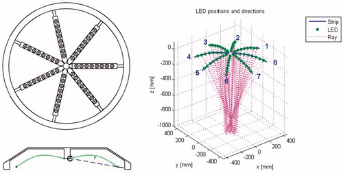
During the concept phase, it was chosen to make use of multiple LEDs as light source, since the most recent OR lights contain LEDS. These LEDs are mounted on flexible strips. These strips will be used to alter the direction of the LEDs which are attached to its surface. This way it is possible to control the direction of several LEDs by manipulating a single strip. By combining multiple strips, it is possible to create light fields that have more complex shapes. Placing these strips in a radial alignment creates a system that can move the spots over a large surface area beneath the luminaire. An example about what such a system will look like can be seen in (left). The strips can bend to modify the direction of the LEDs. The angle of the strips must be adjustable to position the light field on the surface. An example of an outcome is given in (right).
Figure 1. Left: bottom view and cross section of a luminaire that uses bendable strips. Right: example of a system state that creates a narrow beam.
2.2. Model simulation with LightTools
The system has been modelled in LightTools to get more insight in how the luminaire system functions in reality. LightTools is a software package that uses models of the real LED-lens combinations and uses them to render light rays that hit a surface which acts as a receiver. The LightTools software is controlled from Matlab. The individual spot locations and orientations that were calculated in the optimisation are used for this analysis. The LightTools code in Matlab connects to the software and translates the coordinates, orientations and power values into instructions that are understood by LightTools. LightTools calculates and returns the results in the form of a two-dimensional matrix.
2.2.1. LEDs
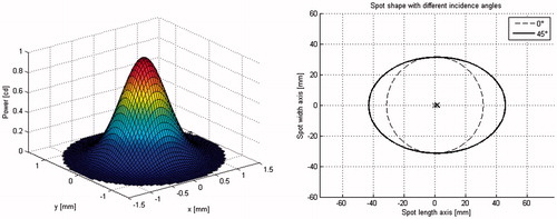
The LED is a fairly simple light source. (left) shows a spot shape with a peak power of 1 cd and a spot width of 1 mm. When the spot hits a surface at an angle, the shape of the spot will become oval and the centre point of the spot will shift slightly away from the middle, as can be seen in (right).
Figure 2. Left: basic spot shape; right: spot shape at angle.
It is needed to adjust the intensity of each LED individually in order to maintain a good light distribution inside the combined light field. Hence, the intensity of these light sources should be controlled. In the final design, it is the idea that this device will receive the input image and translate this into a new system state that makes the new light field possible.
2.2.2. Strip functionality
Each strip has two parameters that determine its functionality. The first parameter is the curvature. By curving the strip, it is possible to control the spread of the focus points of the individual LEDs. The second parameter is the orientation of the strip. This orientation is controlled by the angle between the horizontal plane and the line that intersects both endpoints of the strip. By changing this angle, it is possible to position the combined light field along a linear path. The combined light field will be a result from the curvatures and angles of the individual strips and the intensity of each LED.
The directions of the LEDs are determined by the deformation of the strip. The shape of this deformation depends on the construction of the strip and the way it is actuated. To reduce construction complexity and to keep the calculations simple, a very basic deformation method was chosen for this project. Each strip will be connected to the luminaire body by a hinge at both ends. Deformation is initiated by moving a point in the middle of the strip upwards. It is now possible to stabilise the system against vibrations and unwanted deformations, because the strip is handled in the middle as well as at the end points.
Each strip can be modelled as a thin straight beam that is supported in its endpoints. The hinge on the proximal end of the strip allows rotation and the hinge on the distal end allows both rotation and horizontal displacement. As the ends of the strip start to move together, the strip curves upwards. The shape of the deformation is similar to a scenario where a concentrated load is applied in the middle of the strip in perpendicular direction. The deformation formulas for a beam under similar loading conditions give EquationEquation (1)(1)
(1) for the deflection of a point somewhere on the strip
(1)
(1)
The directions of the LEDs are perpendicular to the surface of the strip, so the derivative of this function gives the direction of the LED somewhere on the strip. During the optimisation process, the position and direction of each LED is calculated many times. Therefore, it is desirable to simplify this formula to speed up the calculations. The strip in the final design will be thin compared to its length. In that case, the deformation will take a shape that is very close to the shape of the positive half of a sine wave.
2.2.3. LED positions
When a strip curves upwards, an LED that is attached to its surface follows this movement. Since the LED is fixed to the strip, the location of the LED is determined by the curve length of the strip section which starts at the hinge point and goes up to the position of the LED. When the x-position is known the y-position can be determined.
2.2.4. Combined beam shape
Each LED has a specific direction in which it emits its light. This creates a line that determines where the brightest point of the spot will be located on an intersecting surface. These lines need to intersect to create the desirable narrow waist in the area between the luminaire and the surface.
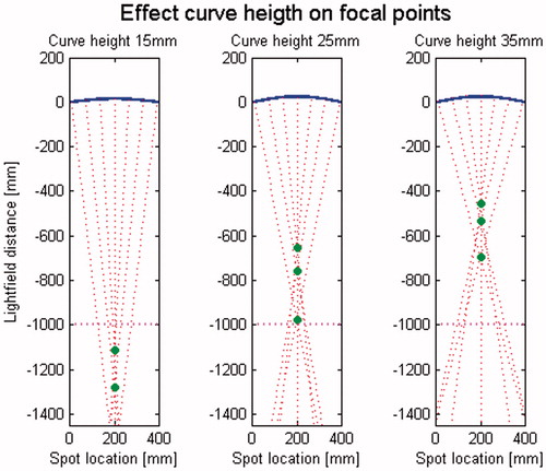
When the strip curves, the direction of the individual LEDs are altered and the lines start to intersect. The distance of the intersecting point of two LEDs decreases as the curvature increases. Due to the sine-shaped curvature, there will not be a true focus point where all directional lines intersect. The effect can be seen in . The green dots indicate where two opposite lines intersect. For curve heights larger than 25 mm, the intersecting lines create a waist somewhere between the surface and the luminaire. This waist is desirable because it gives room to the working area of the surgeon where no light will be blocked. As the lines do not intersect, the final light field will always be slightly larger than a single spot.
Figure 3. Effect of strip curvature on LED focus point.
2.2.5. Strip angle
To move the combined light field of a single strip inside the total light field, it is needed to alter the angle of the strip. Modifying the angle moves the distal point of the strip up or down. This change in orientation modifies the spatial location and direction of the LEDs. The primary effect is that the locations of the projected spots are shifted along the surface. Another effect is that the angle of incidence changes for each of the LEDs. A third effect is that the distance to the target surface is altered. The secondary effects of an elliptical spot shape and the change in spot diameter are not used in the optimisation. Incorporating these effects would mean a major increase in computational complexity with only minor effects on the resulting outcome.
2.3. Experimental validation with prototype
A physical model of one of the strips has been built to evaluate the model (). The decision to build only one strip and not the entire luminaire is made to reduce the building cost of the test setup. It is not essentially needed to analyse a system with all strips because each strip functions as an individual entity inside the luminaire. The light field that is produced by an individual strips is simply summed with the light fields of the other strips to form the main light field. The modification of the shape of the strip is done by hand. The orientation in space of the strip is done using a tripod. The brightness of the LEDs is controlled using a micro controller.
Figure 4. Model top view, 1: stationary frame; 2: rotating frame; 3: LED holder; 4: micro controller; 5: constant current source; 6: height rod; 7: angle rod.
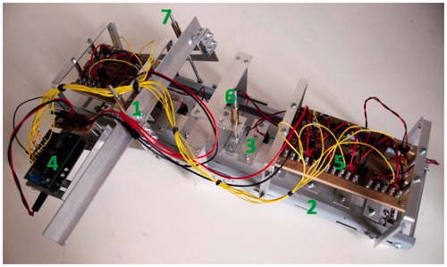
The chosen combination of an LED with a certain lens is a very important aspect of the luminaire system. It is also a very limited choice because it depends on what type of lenses and optics are available. It became clear that most LED-lens systems project a much bigger spot size. Only a few combinations came close enough and of those systems only one type was generally available. The LED light source is a Cree XP-C high power LED with a 26.5 mm Narrow Spot Plain TIR lens from Carclo-optics. A Nikon D5000 camera (Tokyo, Japan) with an 18-105mm lens set at 35 mm was used to make photographs of the illuminated surface.
3. Results
Multiple design choices such as strip number, LED number, LED power, spot size, and LED strip position need to be made to come to a properly functioning luminaire system. A thorough examination of these different options tells the effect they have on the way the device will function. The effect of strip number and LED power will be given as an example.
3.1. LightTools model simulations
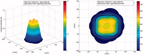
The produced light field data are given in . The Z-axis can be normalised like in (Left), or it can show the actual luminous intensity like in (right). For the normalised representation, the generated intensity values have been divided by the target luminous intensity. This makes it easier to compare settings with different target intensities. The black line inside the graph shows the outline of the target light field which helps to judge how well the generated light field matches target light field. A text box inside the graph shows several settings that were used to generate the light field.
Figure 5. Simulated light field data. Left: light field isometric; right: light field contour.
After examining the effect of the previously listed design choices, an analysis is done to determine the effect of several input factors on the system’s performance, such as strip number and LED power.
3.1.1. Strip number
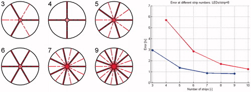
The number of used strips is a primary factor in the resulting light field. Each strip is only capable of placing its spots close together, or creating an elongated light field. The orientation of this light field inside the combined light field depends on the radial alignment of the strip. Assuming that equal angles are used between the strips, then it makes sense to use an uneven number of strips. An even number of strips would have the negative effect that the axis over which two opposite strips can position their light field would coincide. This reduces the number of axis that cross the target light field by a factor 2, as can be seen in where using six strips gives the same number of axis as when using three strips. The higher the number of axis, the better the luminaire is able to spread the light over the target light field. The effect that an added strip has on the performance reduces as more and more strips are used as can be seen in (right). The blue line shows the resulting error value when an uneven number of strip is used and the red line when an even number is used. As expected the performance with an uneven number of strips is much better. The blue line is no longer decreasing when more than seven strips are used. These error values are generated using the same setting and target field, with only the strip number varying. The complexity of the target light field and the diameter of the LEDs will also influence these results. This means that it might be beneficial in other situations to use more than seven strips. On the other hand, using a high number of strips increases the complexity of the system. Another limit to the number of used strips that can be used is the space it takes inside the luminaire. For most following settings a strip number of 7 is used.
Figure 6. Effect of strip number on illumination axis, left: configuration for different number of strips; right: effect of strip number on illumination.
3.1.2. LED power
The user input consists of a shape and a target intensity. Whether the system is able to achieve this target intensity largely depends on the power of the LEDs. The available power is still one of the main challenges during development of this system, although LEDs are becoming more and more powerful. The way the system functions is different from current multi LED systems in that, with an adaptable light field, not all LEDs point at the same spot. This means that a single LED will have to provide a bigger contribution to the illumination of a certain part of the combined light field. A light field has been generated at a range of different LED peak powers to analyse what illumination levels can be expected of the system.
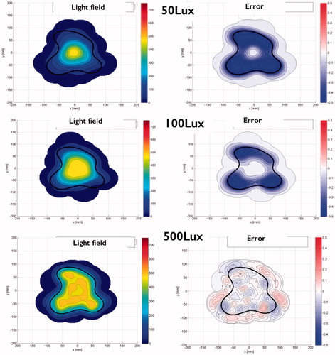
The target light field is set at a value of 500 lux. shows the produced light and error fields. At low power levels of 50 and 100 lux, the system is clearly unable to fill the fairly large target light field. The required levels are only reached in the centre of the light field where many spots are located close together due to the crossing of the strip’s illumination axis. At 200 lux and higher, the system is able to produce a much better image.
Figure 7. Effect of LED intensity on light shape accuracy (7 strips, 8 LEDs). Left: the light field; right: the error.
3.2. Experimental validation with prototype
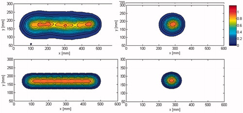
The first setting is set at a curve height of 0 mm, so the strip is completely flat. This gives a very long light field, as can be seen in (left). The light field that was created by the system does not look as smooth as the light field created in Matlab (, bottom). This is mainly caused by the directional errors of the LEDs. The result of these errors is that some spots overlap more than others, which causes a higher intensity value on one side of the spot and a lower intensity value on the other side. It is also clear that the light field is a little wider in vertical direction than the computer-generated light field. This is caused by the slightly wider spots and also misalignments of the LEDs in y direction. The resulting light field clearly shows these differences in width and smoothness. Increasing the curve height to 22 mm moves the spots closer together (, right). This improves the smoothness of the light field. There is still clearly a difference in the width of the LEDs. The resulting light field shows that there are no longer areas where the intensity is lower than the calculated value.
Figure 8. Light field of one strip with 10 LEDs. Top: results with prototype (photograph) and bottom: simulation results with LightTools. Left: curve height 0 mm; right: curve height 22 mm.
4. Discussion
In this paper, a new concept for an adaptable surgical light is presented and evaluated. Although the analysis shows promising results, the design is far from being a fully optimised device. During the project, it became clear that many different aspects come into play when a system is designed that can modify the shape of a light field. The basic idea of placing LEDs on a bendable surface is very simple and elegant. From this simple idea, a system evolved with many different subsystems and variables that all influence the functionality in their own way. Each subsystem on its own is not complex, but the complexity comes from the interdependency between them. It was clear that each subsystem had to be examined individually to see the influence it has on the system. During these analyses, the abilities of the system became visible.
Standard circular spots with a Gaussian distribution were examined during this research, but it is very likely that further improvements could be achieved when additional shapes and or sizes are used. Some light field shapes can benefit from this, but for others it might be a negative effect. Using a radial alignment of strips results in a high concentration of spots axis in the centre of the light field. The spot concentration is lower towards the edges. It is possible to place additional LEDs in certain locations on the luminaire that can provide extra light field coverage. There is space in between the strips to place these LEDs. A simple solution could be fixed LEDs that can be turned off is they are focussed on an area where no light is needed, but also more complex solutions are possible. The disadvantage is that it will make the system more complex.
The current fixed spot size limits the system to cope with various light field sizes, causing irregular light distribution along the central area of the light field. If the spot size is able to increase in diameter when a larger light field is required, then the overall smoothness of the light field will increase. To achieve this, the lenses in front of the LEDs will have to be actuated. It is possible to design a system where the spot size for all LEDs on a single strip are controlled with one actuator, which will less complex system compared to control over each individual lens, but will still be beneficial because in the case of a large shape, all LEDs need a change in spot width. It will however increase the weight and size of the components that are connected to the strips.
The strips use a very basic deformation to position the LED spots. Using other deformation shapes will have effect on the spot distribution inside the combined light field. These different deformation shapes can be achieved in many ways, for example, applying a bending moment on the end of a strip, using a strip material that is not uniform in thickness, forced deformation with an extra actuator, etc. One of the disadvantages of the current deformation shape is that there is no setting where all spots coincide in the light field. This means that the smallest possible size light field is bigger than the spot size ().
With the current evenly spaced configuration of LEDs on each strip, many spots in the combined light field are located in the centre of the light field. This is often the location where the highest brightness is required in the case that a non-uniform light field is required by the surgeon. On the other hand, this configuration will lower the maximum illumination near the edges of larger light field shapes. If the system is unable to provide the required intensity, is it possible to place more LEDs towards the ends of the strip and fewer in the middle.
The decision to build only one strip and not the entire luminaire is made to reduce the building cost of the test setup. It is not essentially needed to analyse a system with all strips because each strip functions as an individual entity inside the luminaire. The light field that is produced by an individual strip is simply summed with the light fields of the other strips to form the main light field. Another decision to keep the system simple is to modify the shape of the strip by hand.
The input system now does not make use of an automated feedback system. Adding a camera inside the luminaire could provide valuable information about the actual light field and where improvements are needed. During the experiment with the modelled strip, it became clear that with a simple analysis it was possible to calculate accurate normalising factors for the power of the LEDs. Such features could improve performance without adding workload to the surgeon.
5. Conclusions
The simulation shows that the system is able to produce light fields that can have fairly complex shapes at a good range of different sizes. The validation with physical test model indicates that the system is able to modify the light field in real time and therefore it could be a way to improve lighting of the surgical field in the operating room.
Disclosure statement
No potential conflict of interest was reported by the authors.
References
- Matern U, Koneczny S. Safety, hazards and ergonomics in the operating room. Surg Endosc. 2007;21(11):1965–1969.
- Patkin M. What surgeons want in operating rooms. Minim Invasive Ther Allied Technol. 2003;12(6):256–262.
- Berguer R. The application of ergonomics in the work environment of general surgeons. Rev Environ Health. 1997;12(2):99–106.
- Berguer R. Surgery and ergonomics. Arch Surg. 1999;134(9):1011–1016.
- NEN-EN-IEC 60601-2-41. Medical electrical equipment. Particular requirements for the basic safety and essential performance of surgical luminaires and luminaires for diagnoses. Geneva: IEC; 2009.
- Knulst AJ, Stassen LPS, Grimbergen CA, et al. Choosing surgical lighting in the LED era. Surg Innov. 2009;16(4):317–323.
- Knulst AJ, Stassen LPS, Grimbergen CA, et al. Standards and performance indicators for surgical luminaires. Leukos. 2009;6(1):37–49.
- Knulst AJ, Mooijweer R, Jansen FW, et al. Indicating shortcomings of surgical lighting systems. Minim Invasiv Ther. 2011;20(5):267–275.
- Berman J, Leiter RB, Yuman F. Lighting in the operating room: current technologies and considerations. In: Yuman F, Giulianotti PC, Lewis J, et al., editors. Imaging and visualization in the modern operating room. New York: Springer; 2015. p. 3–15.
- Beck WC. Lighting the operating room – criteria and choice. AORN J. 1971;14(4):46–49.
- Beck WC. Choosing surgical illumination. Am J Surg. 1980;140(2):327–331.