
ABSTRACT
Roches moutonnées are typical landforms of glacial erosion developed in hard rocks, with an asymmetric profile caused by abrasion and lee-side plucking. In eastern Sweden, some roches moutonnées show extensive damage, including open fractures, disintegration into blocks, fracture caves and short boulder trains. Disintegration increases along ice-flow directions during deglaciation of the last Weichselian Fennoscandian Ice Sheet, indicating a subglacial origin: limited edge rounding can be explained by a combination of hard rock, slow abrasion rates and disintegration just prior to deglaciation. The roches moutonnées initially developed in kernels of gneissic rocks with a wide fracture spacing (large block size) and interlocking fracture pattern, and hence high overall rock mass strength. Dilated fractures and ‘fracture caves’ occur up to 15 m below the ice-bed interface. It is proposed that hydraulic jacking by overpressured water opened up the rock mass along pre-existing fractures. Jacking reduced rock mass strength, allowing glaciotectonic deformation of the roches moutonnées. Uneven hydraulic jacking led to uplift of individual fracture-bound blocks above the pre-existing smooth, abraded surface of the roches moutonnées, creating blunt, step-like edges. These edges allowed high ice pushing forces to act on large blocks: where blocks extend into the deeper rock mass, they further aided the disintegration of the rock mass. The disintegrated roches moutonnées can be regarded as transient features between intact bedrock and complete disintegration into boulders. The jacking-disintegration-transport sequence is characteristic of glacial ripping and very different from classic lee-side plucking.
Introduction
Roches moutonnées and whalebacks are rock hills that occur in their thousands in deglaciated landscapes of areal scour (e.g. Glasser and Warren Citation1990; Rea and Evans Citation1996; Roberts and Long Citation2005; Krabbendam and Bradwell Citation2014). They develop invariably fractured hard bedrock, commonly in crystalline basement rocks. The surrounding lower ground comprises normally more erodible rock with denser fracture spacing, for instance, along fracture-guided valleys (Mathes Citation1930; Johansson et al. Citation2001; Krabbendam and Bradwell Citation2014). Roches moutonnées are asymmetric rock hills with smooth abraded stoss faces and sharp lee-side steps from which blocks have been removed by plucking – or quarrying (Rastas and Seppälä Citation1981; Sugden et al. Citation1992; Roberts and Long Citation2005; Benn and Evans Citation2010; Glasser et al. Citation2020). Plucking is linked to the development of lee-side cavities, with an inflow of basal meltwater subjected to water pressure fluctuations (Iverson Citation1991; Sugden et al. Citation1992; Anderson Citation2014). Whether a rock hill develops a whaleback or roche moutonnée shape is controlled by: (i) the glaciological regime, with faster sliding and thin ice favouring cavity formation and hence plucking (e.g. Evans Citation1996; Roberts and Long Citation2005); and (ii) the spacing and orientation of rock fractures, since most block removal utilizes pre-existing fractures (Dühnforth et al. Citation2010; Krabbendam and Glasser Citation2011; Hooyer et al. Citation2012).
In central east Sweden, roches moutonnées are locally partially disintegrated, with large voids between blocks, disrupted top-surfaces, and locally containing substantial ‘fracture caves’, indicating disintegration at depth. Previous explanations for this disintegration have included (i) earthquakes (Sjöberg Citation1987, Citation1994; Mörner et al. Citation2000; Mörner and Sjöberg Citation2018), (ii) explosive methane venting (Mörner Citation2017) and (iii) some form of glaciotectonics (Lundqvist Citation1987; Lagerbäck et al. Citation2005). The earthquake hypothesis posed that large magnitude (M > 7) earthquakes were responsible (Mörner et al. Citation2000), with profound implications for the magnitude of post-glacial seismicity in eastern Sweden. Building on work of Lagerbäck et al. (Citation2005), Hall et al. (Citation2020) proposed a process termed glacial ripping, where overpressured subglacial groundwater disrupts the shallow rock mass by hydraulic jacking, some form of glaciotectonics further disintegrates the bedrock, ultimately leading to destruction of bedrock highs and deposition of boulder spreads.
Part of the distinction between the above processes hinges on whether disintegration occurred subglacially, at the ice margin, or proglacially after local deglaciation (earthquakes). This study addresses the following questions: What was the geometry of disintegration of roches moutonnées: radial, random, or is there an asymmetry to the disintegration? Is only the surface layer disintegrated, or does the disintegration reach deeper in the rock mass? Did disintegration occur subglacially or proglacially? What is the most likely mechanism of disintegration? What are potential constraints as to why some roches moutonnées are disintegrated and others not?
To answer these questions, we present data on fracture patterns, block size and shape in disintegrated roches moutonnées in Uppsala and Gävleborgs counties in eastern Sweden (). We analyse the kinematics of fracture dilation and rock hill disintegration and discuss possible disintegration mechanisms and the glaciological and geological constraints on these.
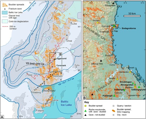
Figure 1. (A). Fennoscandian Ice Sheet, with selected Weichselian ice margin positions, interpreted distribution of cold-based ice during deglaciation, Baltic Ice Lake (Stroeven et al. Citation2016), boulder spreads (SGU data), fracture caves in disintegrated roches moutonnées (Sjöberg Citation1994). YD = Younger Dryas limit. (B). Map with locations and study areas, separated by feature type; boulder spread distribution. Some additional fracture caves reported by Sjöberg (Citation1994) also indicated. DTM after Aster GTOPO30. Figure © Svensk Kärnbränslehantering AB.
Setting
Eastern Sweden () is underlain by basement gneisses formed 1900–1800 Ma ago, and cooled shortly thereafter into the brittle regime (T ∼ < 400 °C) (e.g. Sandström et al. Citation2009; Stephens Citation2010). The basement gneisses were first exhumed in the Mesoproterozoic and subsequently subjected to several cycles of burial and exhumation associated with deposition and erosion of foreland and shelf basins (e.g. Larson et al. Citation1999; Huigen and Andriessen Citation2004), but consistently remained in the brittle regime. Basement gneisses have thus been episodically gathering fractures for over 1.5 billion years; these fractures are commonly coated with minerals such as epidote, chlorite, corrensite, calcite or haematite, mostly during the Proterozoic and the Palaeozoic (Sandström et al. Citation2008, Citation2009). Lithologies include a variety of gneisses, mainly meta-igneous rocks such as gneissic granitic rocks, with minor amphibolite and metasedimentary gneisses (Stephens Citation2010). Ductile deformation was heterogeneous: some rock is strongly foliated, with well-developed gneissic foliations, whilst other parts are more massive with poor fabrics. Fracture patterns are also heterogeneous, with variable fracture density, although fracture density generally increases upward (Carlsson Citation1979; SKB Citation2013; Krabbendam et al. Citation2021).
Fennoscandia was repeatedly glaciated throughout the Pleistocene. The last, Late Weichselian Fennoscandian Ice Sheet (FIS) reached its maximum extent between 17 and 22 ka BP (Stroeven et al. Citation2016). During deglaciation ice margins retreated rapidly and continuously across central eastern Sweden: early Holocene retreat rates over Uppsala county are estimated at 300–350 m/yr (Strömberg Citation1989; Stroeven et al. Citation2016). In lower ground, retreat after 16 ka was by calving in a lacustrine (Baltic Ice Lake) to marine (Yoldia Sea) setting (Lundqvist Citation1987; Andrén et al. Citation2011; Stroeven et al. Citation2016). High interpreted subglacial meltwater fluxes (Jansen et al. Citation2014; Greenwood et al. Citation2017; Shackleton et al. Citation2018), combined with widespread evidence for abrasion (Sohlenius et al. Citation2004) and ice-sheet modelling (SKB Citation2010) show that the ice sheet in eastern Sweden was warm-based during deglaciation.
The glacial geomorphology of eastern Sweden is dominated by a landscape of aerial scour with alternating rock hills and hollows; shallow valleys commonly following kilometre-long fracture zones (e.g. Hall et al. Citation2019). Relative relief is typically 10–20 m, but is highly variable, depending on the depth of erosion beneath the sub-Cambrian unconformity and the degree of glacial streamlining (Hall et al. Citation2019). Spreads of large angular boulders (Lagerbäck et al. Citation2005), termed boulder spreads (distinct from periglacial block fields) cover areas of 10−2 to 102 km2 have been interpreted as the product of glacial ripping of rock surfaces (Hall et al. Citation2019, Citation2020).
Methods, datasets and terminology
This paper reports primary observations obtained during fieldwork, and interpretations of orthorectified air photos, Digital Elevation Models (DEM) and hill-shaded relief maps from Lantmäteriet (the Swedish Mapping, Cadastral and Land Registration Authority). Outlines of blocks, visible on the orthorectified air photos, were digitized in a GIS, from which horizontal X and Y dimensions were derived. In the field, additional data such as height (Z) of blocks, and orientation (azimuth and dip) of abraded surfaces and striae, were collected to determine block size and rotation. Abraded surfaces are smooth, commonly gently curved and have striae; fracture surfaces are straight, commonly coated with chlorite or haematite, and commonly have plumose ornamentations (e.g. Pollard and Aydin Citation1988). The term ‘block’ is used for a fracture-bound block still in contact with adjacent blocks, and in situ or nearly so. Once a block is separated from its neighbours, it becomes a boulder (0.25–4 m across) or a megaclast (>4 m across), following Terry and Goff (Citation2014). Block and boulder sizes for boulder spreads, quarry sections and roches moutonnées are reported as a nominal intermediate B-axis based on the total volume (B-axis = ∛ V) or, if no measurements for height were available, as a proxy B-axis based on the surface area (B-axis = √A).
Results
Three disintegrated roches moutonnées were analysed in detail (Rövargrottan, Bodagrottorna, Gillabergrytta), with short descriptions from three additional sites (Grindstugan, Pukberget, Trollberget; B for locations). Most are assumed to have had a roche-moutonnée geometry prior to disintegration, however, the original form for Trollberget is not known, and Gillabergrytta forms part of a larger rock hill with nested roches moutonnées and whalebacks.
Rövargrottan
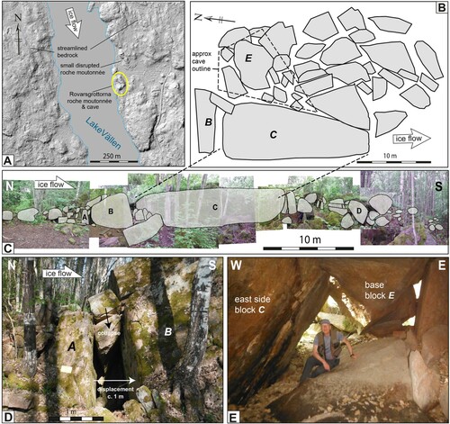
Rövargrottan (also named Tjuvgrottan) is a c. 50 m long, 6 m high bedrock hill on the east shore of Lake Vällen (A), set in massive, poorly foliated granitic rock. The N-S long axis is parallel to south-directed ice flow during deglaciation. Extensive boulder spreads occur to the east; to the north is another smaller disintegrated roche moutonnée, suggesting widespread disruption. Vertical fracture sets occur as a N-S and an E-W set. The largest block (C) measures L = 16 m; H> 3 m; W = 5 m, with a volume of > 260 m3 (B,C). Two vertical metre-wide gaps occur: between blocks A-B and between blocks B-C. The fracture surfaces bounding gap A-B can be matched so block B was displaced c. 1 m with respect to block A, and the smaller blocks at the top of the gap have partially fallen in (D). Block B is c. 1 m higher than up-ice block A forming a pronounced stoss face. The fracture surfaces bounding gap B-C cannot be matched, and smaller blocks in between were more or less in situ; nevertheless, blocks B and C must have moved apart by c. 0.5 m for the smaller blocks to collapse downward. Displacements indicate overall N-S extension. A triangular fracture cave occurs east of block C, with its roof formed by block E (B,E). The arrangement of the smaller blocks east of block C (B) suggests they were translated further southwards than block C and rotated clockwise along vertical axes, akin to dextral strike-slip faulting in structural geology. This is consistent with the triangular shape of the cave below these blocks. Voids between blocks increase in width southward. Block D shows an abraded surface, with subvertical striae: indicating rotation of c. 90°.
Figure 2. Rövargrottan: disrupted roche moutonnée with fracture cave. (A). Setting of Rövargrottan, shaded relief map, © Lantmäteriet. (B) Sketch map of disrupted roche moutonnée. Approximate outline of cave indicated. (C) North-south section; outlines constructed from stitched photo panorama. (D) Detail of gap between block A and block B. (E) Cave to east of block C, view to the north. Figure © Svensk Kärnbränslehantering AB.
Interpretation of Rövargrottan
The overall disintegration has a N-S asymmetry, consistent with displacement by south-directed ice flow. Some displaced blocks (in particular block B) have steep stoss-side faces, allowing for a component of ice-push. If southward ice flow was responsible for disintegration, this implies metre-scale southward movement of the very large block C (V = 260 m3).
Gillbergagrytet
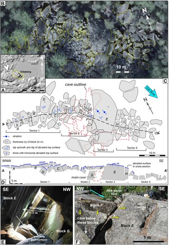
The Gillbergagrytet feature, SE of Halstavik, occurs on the blunt stoss-side of a larger, flat-topped bedrock hill, south of a shallow valley (A). The c. 15 m high rock step trends WNW-ESE, oblique to the regional SSE-directed ice flow (B). Lithology is a coarse-grained, poorly foliated granite gneiss, with wide (>1–6 m) fracture spacing. Vertical fractures occur in WNW-ESE and NE-SW trends (see also Sjöberg Citation1994). Most surrounding bedrock surfaces are intact, with well-developed abraded surfaces in the NE, but Gillbergagrytet consists of a jumbled mass of disrupted and disintegrated rocks, covering an area of c. 80 by 40 m, and is described in four sectors.
Figure 3. Gillbergagrytet: disrupted roche moutonnée with fracture cave. (A) Setting of Gillbergagrytet, shaded relief map © Lantmäteriet. (B) Orthophoto, © Lantmäteriet, with outline of blocks. (C) Map, based on orthophoto and field work. Height (in m) of selected blocks indicated; dip azimuth and dip of selected blocks shown. Approximate outline of cave indicated after Sjöberg (Citation1994). (D) WNW-ESE cross-section, with noted abraded surfaces shown. Line of section on (A). Some blocks are lettered for cross-referencing and mentioned in text. (E) Cave interior: fracture surfaces of blocks E and G match and show displacement of block E. (F) Oblique stoss-side of block E, with relative subsidence of block F. Figure © Svensk Kärnbränslehantering AB.
Sector 1, to the WNW, shows only minor disruption, with blocks separated by 0.1–0.5 m wide, 1–3 m deep voids, and relative vertical displacement < 0.5 m. Most blocks show abraded top surfaces. In the WNW, these abraded surfaces are subhorizontal (block A, B), but further SE these surfaces dip c. 30° west (block C), or east (block D), indicating increasing block rotation and tilting.
Sector 2 comprises a jumble of smaller blocks (0.5–4 m3). Many blocks have rotated significantly (>90°) showing a higher degree of disintegration. Sector 2 overlies the main cave entrance system (C). The two NE-SW trending fracture surfaces that bound the cave entrance passage (between blocks E and G; D) match and show c. 2–5 m relative NW-SE displacement. Most cave passages are formed by separation along the two dominant vertical fracture sets; only a few are formed along the horizontal fractures. Cave passages are up to 5 m wide and 6 m high, indicating <5 m horizontal displacement of the blocks in a SE direction. Sector 2 contains numerous blocks <1–2 m high, much smaller than in Sector 1 and 3, indicating discontinuity of subhorizontal fractures.
Sector 3 is dominated by the very large block E, > 5 m high, and > 800 m3 in volume (C,E). Its top surface is an abraded surface with striae to 160°, indicating limited block rotation. The top surface of block E is c. 0.5–1 m higher than the (jumbled) top surface of Sector 2, indicating relative subsidence of Sector 2 (e.g. block F, C,E). Block E thus displays a pronounced NW-facing stoss-side face (F). To the SE, several blocks have been ‘cleaved off’ block E, showing toppling towards the SE (e.g. block H; D).
Sector 4 is a jumble of large blocks (5–45 m3), with strongly tilted (10° to >90°) abraded surfaces. Most blocks only display fractured surfaces: blocks with abraded surface were either inverted or removed. The rock mass has lost coherence and is in essence a dense boulder spread: not a single block retains an original orientation. The top surface of Sector 4 is 2–4 m below the top surface of block E, showing relative subsidence, but itself shows 3–5 m deep voids, indicating collapse and disintegration to a total depth of 7–9 m, consistent with the depth of the cave below Sector 2. Further loose boulders occur up to c. 20 m ESE of Sector 4. Minor edge rounding (c. 1–4 cm) occurs in Sectors 1 and 3, as seen on block E (F).
Interpretation Gillbergagrytet
Overall Gillbergagrytet shows asymmetric disruption, with block displacement, subsidence, tilting and void width, all increasing towards the ESE, broadly consistent with a SE-directed ice flow. The step-like stoss side of block E, with an abraded top edge, suggests it moved to the SE or ESE, consistent with ice-flow, creating void spaces in its wake and resulting in collapse, subsidence and formation of voids and the fracture cave beneath Sector 2. Block E has moved towards the ESE, but this movement appears to be arrested. Block size is highly variable, (from <1m3 to > 800 m3) and hence the fracture network was highly irregular.
Bodagrottorna (Boda)
Bodagrottorna, or Boda, NW of Iggesund, consists of a large c. 20 m high, disintegrated roche moutonnée (c. 5000 m2, at c. 30 m a.s.l., and ) with an extensive cave system, developed in coarse-grained gneissic, poorly foliated granodiorite (Sjöberg Citation1994; Carlsten and Stråhle Citation2000; Mörner et al. Citation2000; Wänstedt Citation2000). The site lies in a c. 10 km2 area of boulder spreads; intact roches moutonnées occur 1.5 km to the north. Local ice flow direction likely changed during glaciation: overall streamlining suggests eastward ice flow; flow offshore during deglaciation was to the SE (Greenwood et al. Citation2017), whereas E-W trending moraines south of Iggesund suggest southward ice flow. Two elongate boulder spreads, near Boda (but originating from smaller rock hills, now largely destroyed, B) suggest SSE ice flow during deglaciation.
Figure 4. Bodagrottorna roche moutonnée. (A) Setting of Bodagrottorna roche moutonnée (centre), on hill-shaded relief map (© Lantmäteriet). Stippled areas mapped by SGU as boulder spreads. (B) Orthorectified air photo of Bodagrottorna roche moutonnée and immediate surroundings. Two linear boulder spreads extend in a SSE direction. Boreholes locations after Carlsten and Stråhle (Citation2000). (C) Digitised outlines of blocks on orthorectified airphoto (© Lantmäteriet). Numbers indicate block height (z, in m), measured in the field. Line of section for (D) is shown. Location of photos in are indicated. (D) Cross-section of the disrupted roche moutonnée. Approximate limit of disintegration at depth after Wänstedt (Citation2000). Figure © Svensk Kärnbränslehantering AB.
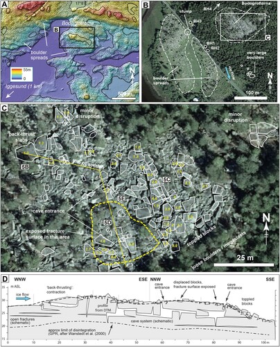
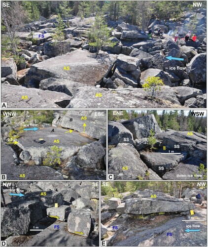
Figure 5. Bodagrottorna roche moutonnée. (A) Overview photo. In the foreground most surfaces are abraded (AS), in background is an exposed fracture plane (FS). (B) Slab-shaped block, with void in up-ice direction. Down-ice the block A has shunted beneath block B, by a form of back-thrusting. (C) Blocks with abraded tops showing vertical relative displacement (0.3–1 m), now presenting blunt stoss-sides (SS); view ∼ down-ice. Minor edge rounding. (D). Centre of roche moutonnée. Exposed fracture plane (FS), with displaced and toppled blocks on top. (E) Slab-shaped block with abraded top, resting on subhorizontal fracture plane (FS), with smaller boulders wedged beneath. Figure © Svensk Kärnbränslehantering AB.
Dominant fracture sets comprise a horizontal set and steeply dipping E-W and NW-SE trending sets (Carlsten and Stråhle Citation2000). Fracture data, obtained by downhole radar and video from four boreholes (Carlsten and Stråhle Citation2000; locations on B) replotted against fracture dip (A) shows large but highly variable fracture (<1 to >20 m), with few and short subhorizontal fractures occurring at different depths in different boreholes. The complex fracture pattern generates interlocking blocks of different sizes, rather than the cuboids that derive from simpler, orthogonal patterns.
Figure 6. Bodagrottorna. (A) Fractures observed in boreholes (down hole video and radar) adjacent to Bodagrottorna, replotted from Carlsten and Stråhle (Citation2000). Depth versus fracture dip; open fractures highlighted. Clusters of steep fractures may record the same fracture, due to undulating fractures. (B) Histogram (bins 0.25 m) of block height near surface, measured in the field. All blocks have abraded tops, so this represents depth of first subhorizontal fracture beneath the abraded surface. Figure © Svensk Kärnbränslehantering AB.
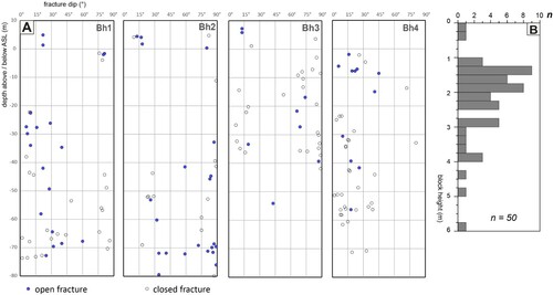
The Boda roche moutonnée contains a ‘fracture cave’ system covering c. 150 × 100 m (Sjöberg Citation1994) ( and ), with 1–5 m wide vertical passages, and 0.3–2 m high horizontal passages at three different levels (cave survey by A. Sidén, published in Sjöberg Citation1994). Passage width, and hence fracture displacement, decreases with depth, to a known depth of c. 10 m. Ground penetrating radar (GPR) and gravity measurements have shown that the cave system at Boda is limited to a depth of c. 5–15 m and is a local feature (Wänstedt Citation2000).
Hall et al. (Citation2020) described an overall asymmetry of block movement, consistent with ice-flow direction. Here we provide more detailed analysis of block size and displacement. On partially freed blocks, abraded and fracture surfaces can be readily distinguished. In the north and NE, disruption is minor, with minor tilting (<10°) of abraded surfaces, with voids < 0.3 m wide between blocks, and <0.2 m relative vertical displacement. On the NW (stoss) side, some large slab-shaped blocks show subhorizontal voids and were pushed beneath down-ice blocks, in a back-thrust-like arrangement (B). On the highest part of the hill, blocks were uplifted with respect to adjacent blocks and formed 0.3–1 m high blunt stoss faces (C). Between the two main cave entrances, a top layer of blocks has been removed, exposing subhorizontal fracture surfaces (FS on A,D,E). Some blocks remain on these fracture surfaces but have overridden smaller blocks that now occur wedged below larger slabs (E). Minor edge rounding (1–2 cm) is present locally.
The height (z) of the surface blocks measured at Boda varies considerably: adjacent blocks can vary in height between 2 and 4 m. Overall, the height of blocks with abraded tops (equivalent to the depth of the first subhorizontal fracture below the abraded surface) varies between 0.5 and 4 m, occasionally up to 6 m (B). This is consistent with the vertical variation of the cave floors elevations.
A cluster of megaclasts (c. 200 and 90 m3) occurs up to c. 120 m SSE in the forest and originated from the Boda roche moutonnée itself (see also Lagerbäck et al. Citation2005). Boda consists of a disrupted rock hill with numerous very large blocks displaced with respect to each together, with a fracture cave system below (C,D and 5A).
Interpretation Bodagrottorna
The bedrock hill has been disintegrated to a depth of c. 10–15 m. Parts of the near-surface rock mass at Boda were uplifted by at least 1 m along subhorizontal fractures, to account for the separation of subhorizontal fractures. Boda shows the following asymmetries: (i) a general increase in disruption to the SE; (ii) SE-ward shunting by back-thrusting of blocks near the stoss side, suggesting a contractional (‘push’) regime; (iii) on the top of the hill, blocks show vertical uplift as well as translation: here some blocks have been removed to expose a subhorizontal fracture; (iv) on the SE or lee side, numerous blocks show tilting and toppling (see also Hall et al. Citation2020).
Grindstugan
South of Gimo, west of Lake Vällen, is an isolated, small (15 m long; 5 m high), but steep and blunt roche moutonnée (A), developed in coarse granitic gneiss. The large stoss side block remains in situ but the rest of the roche moutonnée has been disintegrated into large (B-axes: 2–6 m) blocks, with voids of 0.1–0.8 m wide in between. Some blocks on the lee-side appear to be ‘missing’. Loose boulders, with B-axes 2–4 m, lie 50–80 m to the south (down-ice) of the disintegrated roche moutonnée. Boulder spreads are mapped 0.7–1.4 km to the north, but not in the immediate vicinity.
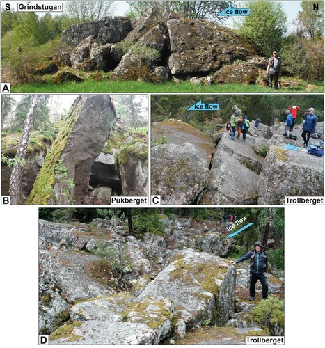
Figure 7. Field photos of selected disintegrated roche moutonnées. (A) Grindstugan: small partially disintegrated roche moutonnée; increasing disintegration down-ice. (B) Pukberget: rock tower with disrupted blocks in back ground. Basal fractures occur at different levels. Height of view c. 6 m. (C) Trollberget: Metre-sized blocks, in domino-style displacement. Top surfaces are abraded. (D) Trollberget: Metre sized block with blunt stoss side facing up-ice. Note minor edge rounding. Figure © Svensk Kärnbränslehantering AB.
Pukberget
The Pukberget disintegrated roche moutonnée, west of Uppsala, is a c. 250 m long ridge, developed in coarse granite gneiss (see also Sjöberg Citation1994; Mörner and Sjöberg Citation2018). The area is characterized by wide valleys, with 20–30 m high rock hills, streamlined along the NNW-SSE orientation. A small esker extends from its southern flank. The Pukberget roche moutonnée, c. 20–25 m above surrounding areas, has similar elevation to nearby rock hills but is shorter and steeper. In terms of boulder size, this is arguably the most spectacular of all disrupted roches moutonnées, but dense forest cover prevents mapping using air photos. On the northern, stoss-side, the roche moutonnée is steep and blunt but also shows incipient disintegration, with deep voids and small rotations of blocks. The core of the hill shows minor disruption, with blocks separated by 0.1–0.5 m wide voids. On flanks, 4–6 m wide blocks are separated by deep crevices; some blocks have been removed, leaving 6 m high rock towers (B). Abraded surfaces are locally recognized; fracture surfaces with coatings are ubiquitous. However, the different heights of the boulders and blocks show that no continuous subhorizontal fractures existed at depth <6 m. On the SSE lee side, blocks lose coherence, become boulders and megaclasts and are dispersed: the entire rock hill has thus been affected by disintegration. In one locality, a well-rounded boulder (c. 0.4 m across) occurs in a subhorizontal void below a much larger block (Sjöberg Citation1994), suggesting vigorous water flow during or after fracture dilation. Sjöberg (Citation1994) reports other small fracture caves nearby, and boulder spreads have been mapped by SGU within 1 km, but air photos suggest that most visible bedrock surfaces of surrounding hills are intact.
Trollberget
NE of Uppsala () is the Trollberget disintegrated roche moutonnée, measuring some 50 × 40 m, situated within a large (6–7 km2) boulder spread composed of large (1–4 m) boulders (C,D). Outside the boulder spread, roches moutonnées remain intact (Lagerbäck et al. Citation2005). The size of the boulders is similar to blocks in the disintegrated roche moutonnée. The blocks in the disintegrated roche moutonnée are arranged in a domino-style arrangement, similar to back-tilted normal-fault blocks, requiring some slip at the base of the blocks. It is possible that this arrangement was relatively stable during ice flow, leaving this part of the rock surface relative intact, whereas elsewhere the upper rock mass was completely ripped into a boulder spread. One large (m sized) block has been tilted with the ice-flow but appears to be ‘stuck’ by other blocks on its lee side: its steep sides would (c. 1 m2) would represent blunt stoss side to ice flow (D). Minor edge rounding (1–2 cm) is present.
Fracture spacing and block size
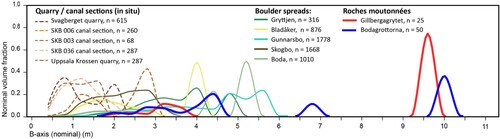
The fracture spacing in the partially disintegrated rock hills is c. 2–6 m, locally up to 10 m as at Bodagrottorna (see also Wänstedt Citation2000). Block size ranges from 1 to 5 m (), with some blocks up to 10 m (B-axis). Block size and fracture spacing is 2–3 times larger than in most other basement rocks in Sweden, which show a typical block size of c. 0.5–1 m, with values > 2 m being rare (); (Carlsson Citation1979; Jern Citation2004; Krabbendam et al. Citation2021).
Figure 8. Comparison of block size in quarries and excavation sections, boulder spreads, and disrupted roche moutonnées (Bodagrottorna and Gillbergagrytet). Nominal B-axis is based on areal extent, used as proxy for boulder/block size. Boulders and blocks with B-axis < 0.8 m were not measured in boulder spreads and roche moutonnées. Figure © Svensk Kärnbränslehantering AB.
Summary of observations
All investigated disintegrated roches moutonnées occur in massive, coarse-grained, granitic rocks with wide fracture spacing and large block size.
The partially disintegrated roches moutonnées form bedrock highs with steep and blunt stoss faces.
Fracture dilation and disruption of the rock mass occurs at depth (typically c. 10 m), including the development of fracture caves, well below the ice-bed interface and the top row of blocks.
Nearer the surface, horizontal and vertical displacement along fractures by 0.1–5 m has formed voids and fracture caves.
Angular blocks, many still with abraded, striated surfaces, are rotated or displaced by 1–10 m.
In several roches moutonnées, the height (Z-axis) of the blocks varies strongly (Boda, Gillbergagrytet, Pukberget): subhorizontal fractures occurred at different depths, but no continuous subhorizontal fractures occur. The original, irregular fracture network delineated a system of interlocking blocks.
Each partially disintegrated roche moutonnée show asymmetry of disintegration of: (i) blocks displaced away from others consistent with local late-glacial ice-flow directions; (ii) an increase in disruption to major disintegration in a down-ice direction; (iii) a trail of loose boulders down-ice from the roches moutonnées (except at Trollberget, which is positioned within a large boulder spread).
The settings of the disintegrated roches moutonnées differ: some are surrounded by mainly intact rock (Gillbergagrytet) whilst others occur in areas with many boulder spreads (Boda, Trollberget). At Rövargrottan, Boda, Pukberget, and Trollberget, the entire roche moutonnée is affected by disintegration, whereas at Grindstugan and Gillbergagrytet, only part of the rock hill is affected.
Discussion
The survival of large roches moutonnées in terrains subjected to multiple phases of subglacial erosion implies that, in general, the resistance of upstanding rock hills is greater than the driving forces exerted by the ice flowing across them. At issue here is the explanation for the (partial) asymmetric disintegration of roches moutonnées in lowland Sweden, involving crystalline gneissic rock with wide fracture spacing, on blunt, steep-sided rock hills.
Previous and other hypotheses
The prevalent hypothesis for the disintegration of roches moutonnées in the present Swedish literature is disintegration by earthquakes, caused by isostatic uplift during and after deglaciation (Sjöberg Citation1987, Citation1994; Mörner et al. Citation2000; Mörner Citation2017; Mörner and Sjöberg Citation2018). This hypothesis is problematic: (i) An earthquake origin can neither explain the systematic asymmetry of disintegration, nor the removal of a large number of blocks, leaving exposed fracture surfaces as at Boda; (ii) Deglacial earthquakes in eastern Sweden are associated with varve disturbance (e.g. Mörner et al. Citation2000). However, the asymmetry of disintegration suggests a subglacial origin (see also below), whereas varve disturbance by necessity occurred proglacially. There is no demonstrable temporal link between varve disturbance and disintegration of roches moutonnées (cf. Mörner et al. Citation2000; Mörner Citation2017); (iii) The mechanism of how purported earthquakes can disintegrate a massive, intact bedrock hill remains unexplained. If this was physically plausible, earthquakes in other (non-glaciated) terrains should also produce such features. To our knowledge, there are no reports of disintegration of high rock-mass strength hills in low-relief landscapes in tectonically active regions. Overall, earthquakes cannot have disintegrated the roches moutonnées and the features cannot be used to constrain the magnitude of palaeoseismic events in Sweden.
An alternative methane venting hypothesis (Mörner Citation2017) suffers from the issue of methane sourcing: basement rocks are normally poor in hydrocarbons, in particular, if no source rocks are nearby, as is the case in east Sweden (e.g. Drake et al. Citation2019). This hypothesis equally cannot explain the asymmetry of disintegration.
Disintegration: subglacial or proglacial?
The evidence of asymmetry of disintegration points to a subglacial origin. In contrast, Sjöberg (Citation1994) and Mörner et al. (Citation2000) argue that disintegration cannot have occurred subglacially, since the edges of the disintegrated blocks are not rounded, and striae have been cut by fractures. There are three problems with this argument. Firstly, plucked faces, undoubtedly formed subglacially, commonly also show sharp edges, in Sweden and elsewhere (Krabbendam and Glasser Citation2011; Bradwell Citation2013; Hall et al. Citation2019; Glasser et al. Citation2020). Secondly, minor edge rounding has in fact been observed on some disintegrated roches moutonnées. Thirdly, abraded surfaces need not necessarily have been formed during the final stage of deglaciation. In east Sweden, there are now better data to constrain the rate of abrasion, and hence the rate of edge rounding. Terrestrial Cosmogenic Nuclide (TCN) dating of samples collected in Uppsala county estimates the total erosion of the tops of roches moutonnées, likely all achieved by abrasion, to be c. 1.6–3.5 m over the entire Weichselian period, involving two stadial phases (Hall et al. Citation2019). Ice sheet modelling suggests a total cumulative sliding distance of c. 3000–5000 km in the same area over the same time span (Näslund et al. Citation2003). This equates to an abrasion rate of c. 0.3–1.1 mm per kilometre sliding distance. Now consider a roche moutonnée disrupted subglacially c. 10 km from the retreating margin, creating some sharp edges. Given that retreat rates are similar to ice sliding velocities (compare Strömberg Citation1989; Stroeven et al. Citation2016 with Patton et al. Citation2017), the maximum sliding distance is c. 5 km before the blocks emerge from the retreating ice margin and abrasion stops. The resultant abrasion is c. 1.5–5.5 mm: even allowing for faster abrasion on sharp edges, such small abrasion would be barely discernible in the field. Neither limited edge rounding nor striae cut by fractures are thus incompatible with a subglacial origin. To satisfy the constraints of minimal edge rounding and asymmetry of disintegration, we conclude that the roches moutonnées were disintegrated subglacially, but close to (<5–10 km) the retreating margin.
Comparison with classic lee-side plucking
The partial disintegration of roches moutonnées studied here involves a form of block release and removal. Some authors regard any subglacial block removal as plucking (Benn and Evans Citation2010). However, most studies concerning plucking document or model a scenario whereby fracture-bound blocks are removed one after another from the lee side, typically involving a lee-side cavity subjected to water pressure fluctuations (Iverson Citation1991; Sugden et al. Citation1992; Hallet Citation1996; Rea and Whalley Citation1996; Hooyer et al. Citation2012; Zoet et al. Citation2013; Anderson Citation2014). This mode of plucking can be described as ‘classic lee-side plucking’, distinct from block removal by other means.
Differences between roche moutonnée disintegration and classic lee-side plucking are: (i) disintegration involves damage to the internal rock mass, with fracture dilation, block displacement and cave development many metres below the rock surface, affecting the rock mass well below the top layer of blocks; (ii) disintegration involves a multitude of fracture-bound blocks (n >100–1000) at the same site, (iii) disintegration affects the stoss and upper surfaces of a roche moutonnée, as well as the lee-side. Overall, the disintegration of roches moutonnées is distinct from, and affects a much larger rock mass than, classic lee-side plucking.
Evidence and origin of water pressure fluctuations
In eastern Sweden, there is local evidence of fracture dilation and hydraulic jacking, and hence elevated water pressures, in the shallow (c. 10–15 m depth) rock mass in particular along subhorizontal fractures, for example, in excavations at Forsmark, where subhorizontal fractures with apertures 1–80 cm are filled with laminated sands and silts (Carlsson Citation1979; Leijon Citation2005; Forssberg et al. Citation2007). Locally, differential dilation of subhorizontal fractures caused uneven uplift of rock blocks, producing sharp steps on the previously smooth abraded ice bed (Forssberg et al. Citation2007). Fracture dilation, with and without sediment fill, has also been observed in other quarries in lowland Sweden (Hall et al. Citation2020; Krabbendam et al. Citation2021). Although it is difficult to ascribe hydraulic jacking to individual fractures in the complex disintegrated roche moutonnées, it is likely hydraulic jacking caused much vertical dilation along subhorizontal fractures.
Whilst the causes of overpressure and hydraulic jacking events in east Sweden have been controversial (Pusch et al. Citation1990; Vidstrand et al. Citation2008; Lönnqvist and Hökmark Citation2013; Talbot Citation2014), recent measurements at the base of the Greenland Ice Sheet have documented frequent (daily in melting season) high-amplitude water pressure fluctuations, ranging between 60% and 99% of overburden pressure in areas well-connected to moulins and subglacial streams, and between 80% and 105% of overburden pressure in poorly-connected regions (Andrews et al. Citation2014; Hoffman et al. Citation2016; Liljedahl et al. Citation2016; Wright et al. Citation2016; Harper et al. Citation2019). Overpressure at the base of the ice sheet can also be caused by supraglacial lake drainage events; in Greenland, these are known to locally and temporarily uplift the ice sheet during the melting season, with extensive ice-bed separation (Das et al. Citation2008; Doyle et al. Citation2013; Lai et al. Citation2021). Given that the late FIS in eastern Sweden was in a similar state as the western Greenland Ice Sheet at present (e.g. the ablation zone of a rapidly melting ice sheet), both mechanisms may have played a significant role in the subglacial hydraulic jacking.
Glaciotectonic processes
Glaciotectonics involves the deformation of the ice bed caused by glacier motion or loading, and can occur in either subglacial or proglacial settings (e.g. Hart Citation1990); and encompasses a wide range of materials, processes and end-products. Most studies of glaciotectonics focus on subglacial till deformation (e.g. Boulton and Hindmarsh Citation1987; Benn and Evans Citation1996; Alley Citation2000) or on folding and thrusting of large, relative coherent rafts or sheets of (frozen) sediment or bedrock in ice-marginal or proglacial settings (e.g. Croot Citation1987; Hart Citation1990; Burke et al. Citation2009; Johnson et al. Citation2013), very different in setting, material and end-product from the disintegration of roches moutonnées.
However, a number of papers describe ‘brecciation’ or ‘glaciotectonics’ affecting the top few metres of subglacial bedrock, (e.g. Croot and Sims Citation1996; Hiemstra et al. Citation2007; Phillips and Auton Citation2008). Schroeder et al. (Citation1986) documents ‘ice-push caves’ in Ordovician limestone below Montreal, very similar to the fracture caves in east Sweden. Hall et al. (Citation2021) also describes partially disintegrated roches moutonnées, as well as boulder spreads, in quartz sandstones in NW Scotland. These processes are similar to the glaciotectonic disintegration of roches moutonnées described herein, except that they all involve relatively friable, and/or well stratified and densely fractured rocks such as mudstone, limestones or sandstone. At issue is whether similar processes can operate in hard basement gneisses with wider (>1 m) fracture spacing.
Forces acting upon a blunt obstacle on the glacier bed and the role of water pressure
To test, conceptually, whether it is plausible that glaciotectonic processes can disintegrate hard basement gneisses with wide (>1 m) fracture spacing, we now consider the balance of resisting and driving forces operating on a rock hill (or: ‘obstacle’) beneath an ice sheet. The driving forces acting upon a subglacial rock obstacle comprise: (i) The drag forces applied by highly viscous ice creeping around the obstacle. These drag forces are proportional to ice velocity and obstacle size and known to be potentially very high indeed (Hallet Citation1979; Cohen et al. Citation2005); (ii) The frictional forces exerted by debris-laden ice sliding over a smooth surface. These forces are relatively low (but not negligible) due to the low friction coefficient along the ice-bed (µ = 0.05–0.3; Cohen et al. Citation2005; Emerson and Rempel Citation2007). The resisting forces of a rock obstacle are controlled by the intact rock strength of the rock (c. 10–20 times higher for hard rock than for ice), and the static friction along fractures. As the rock-rock friction coefficient along fractures is higher (µ = 0.5–0.9; Ramana and Gogte Citation1989) than along the ice-bed contact, under steady-state sliding over a flat surface, sliding ice cannot remove rock blocks. In a rock mass with a complicated, irregular fracture pattern, a complex interplay between the intact rock strength and the fracture friction ensues, involving the concept of rock mass strength (Hoek and Brown Citation1997), making the assessment of resisting forces of a rock obstacle non-trivial. Elevated water pressures within fractures reduce the static friction along these fractures and lower effective rock mass strength, just as rock-mass strength on slopes is reduced during high rainfall events triggering rock slides (e.g. Fan et al. Citation2009). If water pressure exceeds overburden pressure, it may lead to hydraulic jacking, further reducing the rock mass strength and starting the process of rock mass disruption (Carlsson Citation1979; Lönnqvist and Hökmark Citation2010; Krabbendam et al. Citation2021).
Subglacial glaciotectonic disintegration of hard bedrock hills
The widespread occurrence of roches moutonnées and whalebacks in deglaciated basement gneiss terrains (e.g. Rastas and Seppälä Citation1981; Roberts and Long Citation2005), shows that blunt bedrock hills survived long periods of glaciation without significant damage from glaciotectonics: the rock-mass strength of such basement rock hills clearly exceeded ice traction forces under a wide range of conditions. So why are some roches moutonnées in east Sweden disintegrated, but others not? To explore the plausibility and limits of glaciotectonic disintegration of a rock hill by sliding and creeping ice, we discuss a number of simple conceptual scenarios (). We start with end-member scenarios that are not necessarily realistic and then focus on more realistic scenarios.
Figure 9. Conceptual models of glaciotectonic disintegration of roche moutonnées with different internal fracture patterns. Arrows indicate forces exerted by ice; and resisting forces of the rock mass. Arrow size indicates relative magnitude of forces. (A) Whaleback with few/no internal fractures. (B) Short roche moutonnée with continuous subhorizontal fractures. (C) Long roche moutonnée with continuous subhorizontal fractures, simple orthogonal fracture pattern. (D) Roche moutonnée with irregular, interlocking fracture pattern and discontinuous subhorizontal fractures. Figure © Svensk Kärnbränslehantering AB.
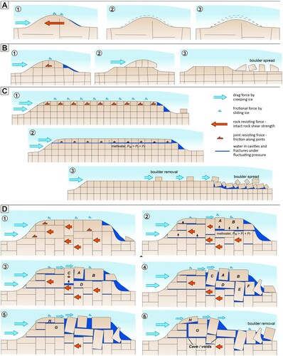
Consider an obstacle of hard bedrock with widely spaced fractures, and few or no subhorizontal fractures (A). The rock mass strength of the obstacle is controlled by the intact rock strength rather than friction along fractures. Since intact rock is stronger than ice (typically by a factor of 10–20, depending on rock type) the resisting forces will be much higher than the driving forces exerted by the ice, and glaciotectonic disintegration is likely impossible. Depending on the fracture density (Krabbendam and Glasser Citation2011; Hooyer et al. Citation2012), plucking may be suppressed too, and the bedrock hill is likely to be solely – and slowly – eroded by abrasion, forming a smooth whaleback.
Now consider a short, blunt rock obstacle, with a simple orthogonal fracture pattern in which subhorizontal fractures form a continuous weakness across the entire obstacle (B). On the smooth top surface, friction forces exerted by sliding ice are low and unlikely to move blocks on their own. However, for a short, blunt obstacle, the much higher ice drag forces may well exceed the static friction along the subhorizontal fracture, and remove the top part of the rock obstacle by shearing along that fracture, as noted by Rastas and Seppälä (Citation1981). Elevated water pressures will assist in lowering the friction along a basal fracture but, if the fracture is sufficiently smooth, may not be required. Glaciotectonic block removal is very likely. This process can work under a range of glaciological conditions and likely operated during earlier glaciations, removing any such ‘vulnerable’ rock hills. In terrains like east Sweden, subjected to multiple cycles of vigorous glacial erosion, any such ‘vulnerable’ rock hills were likely removed by earlier Pleistocene glaciations. This means it is not a realistic scenario for late Weichselian glaciotectonic disintegration of roches moutonnées in east Sweden as documented here.
Further consider a longer, lower obstacle, also with continuous subhorizontal fractures (C). The cumulative static friction along the much longer subhorizontal fractures may exceed the ice drag force on the stoss side, preventing glaciotectonic disintegration. However, if high water pressure occurring at the bed can penetrate into a subhorizontal fracture, the friction along the fracture may be lowered sufficiently to allow wholesale removal of the top rock layer. The scenario is plausible in crystalline rock domains with long, continuous subhorizontal fractures, such as occur locally in lowland Sweden (e.g. Carlsson Citation1979; SKB Citation2013; Krabbendam et al. Citation2021). This scenario is also applicable to gently dipping sedimentary strata, where bedding planes form continuous subhorizontal discontinuities: wholesale block removal, or glacial ripping, has been documented in Ontario and NW Scotland in gently dipping limestone and quartz-sandstone strata, respectively (Bukhari et al. Citation2021; Hall et al. Citation2021).
Finally, consider a bedrock obstacle with a complex, irregular fracture pattern, without continuous subhorizontal fractures, as described for the roches moutonnées herein. The fracture-bound blocks are interlocking and the hill has a high rock-mass strength (D). The resisting forces of the rock mass are likely higher than any ice drag forces exerted on the hill as a whole (D1). Overpressure and hydraulic jacking reduce the friction along the subhorizontal fractures, but the interlocking fracture-bound blocks may prevent further disintegration. One possibility for disintegration is the uplift of individual rock blocks by hydraulic jacking, creating step-like obstacles on the previous smooth bedrock surface (Block A in D2), as recorded at Forsmark (e.g. Forssberg et al. Citation2007; Krabbendam et al. Citation2021). If this happens, the small friction forces acting on the top of the roche moutonnée change dramatically to much larger drag forces, now acting on a blunt stoss face: the sliding ice develops more ‘grip’ on the individual blocks. Block A will exert a horizontal force onto block B. Since both have a subhorizontal fracture, they can slide down-ice (D3). If block C is also uplifted, it cannot easily slide away: instead, it exerts a pushing force onto block D, which in turn pushes block E and F, resulting in disruption below the top row of blocks (D4), one of the main characteristics of disintegrated roches moutonnées. If blocks G and H are also uplifted by jacking (either in the same or a subsequent high-pressure event) then disintegration reaches the stoss side of the rock hill (D5). Block H is subjected to full stoss-side drag force and maybe thrust over lower blocks, leading to further disintegration, affecting the entire rock hill (D6). In a large roche moutonnée, further disruption likely works downward and up-ice, progressively disrupting the rock mass at depth and feasibly forming caves. Further disintegration (not shown) may ultimately destroy the entire hill and turn the blocks into boulder spreads, as per Hall et al. (Citation2020).
The transient nature of disintegrated roches moutonnées
Partially disintegrated roches moutonnées are seen as transient features between an intact rock hill and boulder spreads, within the overall process of glacial ripping (Hall et al. Citation2020). The preservation of such transient features is most likely caused by final deglaciation overtaking the process of disintegration. In that case, roches moutonnées that take longer to disintegrate have a higher preservation potential than those that disintegrate rapidly. The preserved, partially disintegrated roches moutonnées described herein are characterized by larger than average fracture spacing and interlocking fracture patterns, suggesting they were difficult to disintegrate, possibly requiring multiple high water pressure events over multiple melting seasons. In contrast, roches moutonnées with smaller block sizes and continuous subhorizontal fractures may well disintegrate completely in boulder spreads and be removed in a single season: their transient phases have a lower preservation potential.
Conclusions
Disintegrated roches moutonnées in hard, fractured basement rocks in eastern Sweden show a pronounced asymmetry in their disintegration, coincident with ice-flow directions during deglaciation. Trails of boulders extend from some such roches moutonnées, also consistent with local ice-flow directions. Thus, disintegration of roches moutonnées occurs subglacially: limited edge rounding can be explained by a combination of hard rock, slow abrasion rates and disintegration close to the ice margin, just prior to deglaciation. Dilated fractures and fracture caves occur well below the ice-bed interface and indicate that the rock mass is disturbed or partially integrated at depth.
It is proposed that disintegration occurred by jacking-induced glaciotectonic deformation of the roches moutonnées. Hydraulic jacking of pre-existing fractures loosens the rock mass, dilates fractures and may uplift fracture-bound blocks above the smooth ice-bed, creating blunt step-like edges. These edges allow high ice drag forces to act on large blocks: if such blocks extend in the deeper rock mass, they further aid the disintegration of the rock mass.
Glaciotectonic disintegration of roches moutonnées is different from the classic lee-side plucking as it affects the rock mass to greater depth, can affect the entire rock hill and involves and mobilizes a much greater rock mass at the same time.
The disintegrated roches moutonnées can be regarded as transient features between intact roches moutonnées and complete disintegration into loose boulders as part of the glacial ripping process. The preservation of partially disintegrated roches moutonnées is likely caused by the process of disintegration being overtaken by final deglaciation.
Acknowledgements
Sam Roberson is thanked for comments on an earlier version of the manuscript. The authors thank three anonymous reviewers for constructive reviews. Use of SGU mapping data, and elevation data and aerial photographs aerial photos from Lantmäteriet is gratefully acknowledged. MK, AF and RNP publish with the permission of the Executive Director of BGS.
Disclosure statement
No potential conflict of interest was reported by the author(s).
Additional information
Funding
Notes on contributors
M. Krabbendam
M. Krabbendam is a Senior Geologist at the British Geological Survey, Edinburgh. His research encompasses bedrock geology and geomorphology, focussing on glacial erosion mechanisms. His contribution to this study is the conceptualisation of the study, field data collection and analysis, figure preparations, and writing the original draft.
A. M. Hall
A. M. Hall is a geomorphologist, formerly of Stockholm University and now at the University of Edinburgh. His research, mainly in Scotland and Fennoscandia, has explored long-term landscape evolution, glacial geomorphology. Pleistocene stratigraphy and rock coasts. His contribution to this study is the conceptualisation of the study, field data collection and analysis, and writing and reviewing the original draft.
R. M. Palamakumbura
R. M. Palamakumbura is a Geologist at the British Geological Survey, Edinburgh. His research encompasses bedrock geology, focussing on fracture analysis and remote sensing data analysis. His contribution to this study field is data collection and remote sensing data analysis, figure preparations, and contribution to writing and reviewing the original draft.
A. Finlayson
A. Finlayson is a geomorphologist at the British Geological Survey, Edinburgh. His recent research has been focused around applied Quaternary geology in glaciated and upland landscapes, geomorphological hazards, and human-landscape interactions during post-disaster transitions His contribution to this study is remote sensing data analysis and reviewing the original draft.
References
- Alley RB. 2000. Continuity comes first: recent progress in understanding subglacial deformation. London: Geological Society. Special Publications, 176: 171–179.
- Anderson RS. 2014. Evolution of lumpy glacial landscapes. Geology. 42:679–682.
- Andrews LC, Catania GA, Hoffman MJ, Gulley JD, Lüthi MP, Ryser C, Hawley RL, Neumann TA. 2014. Direct observations of evolving subglacial drainage beneath the Greenland Ice Sheet. Nature. 514:80–83.
- Andrén T, Björck S, Andrén E, Conley D, Zillén L, Anjar J. 2011. The development of the Baltic Sea Basin during the last 130 ka. In: Harff J, Björck S, Hoth P, editors. The Baltic Sea Basin. Berlin: Springer; p. 75–97.
- Benn DI, Evans DJ. 1996. The interpretation and classification of subglacially-deformed materials. Quat Sci Rev. 15:23–52.
- Benn DI, Evans DJA. 2010. Glaciers and glaciation. London: Hodder Education. 802 p.
- Boulton GS, Hindmarsh RCA. 1987. Sediment deformation beneath glaciers: rheology and geological consequences. J Geophys Res Solid Earth. 92:9059–9082.
- Bradwell T. 2013. Identifying palaeo-ice-stream tributaries on hard beds: Mapping glacial bedforms and erosion zones in NW Scotland. Geomorphology. 201:397–414.
- Bukhari S, Eyles N, Sookhan S, Mulligan R, Paulen R, Krabbendam M, Putkinen N. 2021. Regional subglacial quarrying and abrasion below a paleo ice stream crossing the shield-paleozoic boundary of central Canada: the importance of substrate control. Boreas. 50:781–805.
- Burke H, Phillips E, Lee JR, Wilkinson IP. 2009. Imbricate thrust stack model for the formation of glaciotectonic rafts: an example from the Middle Pleistocene of north Norfolk, UK. Boreas. 38:620–637.
- Carlsson A. 1979. Characteristic features of a superficial rock mass in southern Sweden. Striae. 11:1–79.
- Carlsten S, Stråhle A. 2000. Borehole radar and BIPS investigations in boreholes at the Boda area. SKB Report, TR-01-02, Svensk Kärnbränslehantering AB.
- Cohen D, Iverson NR, Hooyer TS, Fischer UH, Jackson M, Moore PL. 2005. Debris-bed friction of hard-bedded glaciers. J Geophys Res Earth Surf. 110:F02007.
- Croot DG. 1987. Glacio-tectonic structures: a mesoscale model of thin-skinned thrust sheets? J Struct Geol. 9:797–808.
- Croot DG, Sims P. 1996. Early stages of till genesis: an example from Fanore, County Clare, Ireland. Boreas. 25:37–46.
- Das SB, Joughin I, Behn MD, Howat IM, King MA, Lizarralde D, Bhatia MP. 2008. Fracture propagation to the base of the Greenland ice sheet during supraglacial lake drainage. Science. 320:778–781.
- Doyle SH, Hubbard AL, Dow CF, Jones GA, Fitzpatrick AAW, Gusmeroli A, Kulessa B, Lindback K, Pettersson R, Box JE. 2013. Ice tectonic deformation during the rapid in situ drainage of a supraglacial lake on the Greenland Ice sheet. Cryosphere. 7:129–140.
- Drake H, Roberts NMW, Heim C, Whitehouse MJ, Siljeström S, Kooijman E, Broman C, Ivarsson M, Åström ME. 2019. Timing and origin of natural gas accumulation in the Siljan impact structure, Sweden. Nat Commun. 10:1–14.
- Dühnforth M, Anderson RS, Ward D, Stock GM. 2010. Bedrock fracture control of glacial erosion processes and rates. Geology. 38:423–426.
- Emerson LF, Rempel AW. 2007. Thresholds in the sliding resistance of simulated basal ice. Cryosphere. 1:11–19.
- Evans IS. 1996. Abraded rock landforms (whalebacks) developed under ice streams in mountain areas. Ann Glaciol. 22:9–16.
- Fan X-M, Xu Q, Zhang Z-Y, Meng D-S, Tang R. 2009. The genetic mechanism of a translational landslide. Bull Eng Geol Environ. 68:231–244.
- Forssberg O, Mærsk Hansen L, Koyi S, Vestgård J, Öhman J, Petersson J, Albrecht J, Hedenström A, Gustavsson J. 2007. Forsmark Site Investigation: Detailed Fracture and Bedrock Mapping, Quaternary Investigations and GPR Measurements at Excavated Outcrop AFM001264. SKB Report, P-05-269, Svensk Kärnbränslehantering AB.
- Glasser NF, Roman M, Holt TO, Žebre M, Patton H, Hubbard AL. 2020. Modification of bedrock surfaces by glacial abrasion and quarrying: evidence from North Wales. Geomorphology. 365:107283.
- Glasser NF, Warren CR. 1990. Medium scale landforms of glacial erosion in south Greenland; process and form. Geogr Ann A. 72:211–215.
- Greenwood SL, Clason CC, Nyberg J, Jakobsson M, Holmlund P. 2017. The Bothnian Sea ice stream: early Holocene retreat dynamics of the south-central Fennoscandian Ice sheet. Boreas. 46:346–362.
- Hall AM, Ebert K, Goodfellow BW, Hättestrand C, Heyman J, Krabbendam M, Moon S, Stroeven AP. 2019. Past and future impact of glacial erosion in Forsmark and Uppland. SKB Report, TR-19-07, Svensk Kärnbränslehantering AB.
- Hall AM, Krabbendam M, van Boeckel M, Goodfellow BW, Hättestrand C, Heyman J, Palamakumbura R, Stroeven AP, Näslund J-O. 2020. Glacial ripping: geomorphological evidence from Sweden for a new process of glacial erosion. Geogr Ann A. 110:333–353.
- Hall AM, Mathers H, Krabbendam M. 2021. Glacial ripping in sedimentary rocks: loch eriboll, NW Scotland. Geosciences. 11:232.
- Hallet B. 1979. A theoretical model of glacial abrasion. J Glaciol. 23:39–50.
- Hallet B. 1996. Glacial quarrying: a simple theoretical model. Ann Glaciol. 22:1–8.
- Harper JT, Meierbachtol T, Humphrey NF. 2019. Greenland ICE Project, Final Report. SKB Report, R-18-06, Svensk Kärnbränslehantering AB.
- Hart JK. 1990. Proglacial glaciotectonic deformation and the origin of the cromer ridge push moraine complex, North Norfolk, England. Boreas. 19:165–180.
- Hiemstra JF, Evans DJ, Cofaigh CÓ. 2007. The role of glacitectonic rafting and comminution in the production of subglacial tills: examples from southwest Ireland and Antarctica. Boreas. 36:386–399.
- Hoek E, Brown ET. 1997. Practical estimates of rock mass strength. Int J Rock Mech Min Sci. 34:1165–1186.
- Hoffman MJ, Andrews LC, Price SF, Catania GA, Neumann TA, Lüthi MP, Gulley J, Ryser C, Hawley RL, Morriss B. 2016. Greenland subglacial drainage evolution regulated by weakly connected regions of the bed. Nat Commun. 7:1–12.
- Hooyer T, Cohen D, Iverson N. 2012. Control of glacial quarrying by bedrock joints. Geomorphology. 153-154:91–101.
- Huigen Y, Andriessen P. 2004. Thermal effects of Caledonian foreland basin formation, based on fission track analyses applied on basement rocks in central Sweden. Phys Chem Earth Parts A/B/C. 29:683–694.
- Iverson NR. 1991. Potential effects of subglacial water-pressure fluctuations on quarrying. J Glaciol. 37:27–36.
- Jansen JD, Codilean AT, Stroeven AP, Fabel D, Hättestrand C, Kleman J, Harbor JM, Heyman J, Kubik PW, Xu S. 2014. Inner gorges cut by subglacial meltwater during Fennoscandian ice sheet decay. Nat Commun. 5:1–7.
- Jern M. 2004. Determination of the in situ block size distribution in fractured rock, an approach for comparing in-situ rock with rock sieve analysis. Rock Mech Rock Eng. 37:391–401.
- Johansson M, Olvmo M, Lidmar-Bergström K. 2001. Inherited landforms and glacial impact of different palaeosurfaces in southwest Sweden. Geogr Ann A. 83:67–89.
- Johnson MD, Benediktsson ÍÖ, Björklund L. 2013. The Ledsjö end moraine – a subaquatic push moraine composed of glaciomarine clay in central Sweden. Proc Geol Assoc. 124:738–752.
- Krabbendam M, Bradwell T. 2014. Quaternary evolution of glaciated gneiss terrains: pre-glacial weathering vs. glacial erosion. Quat Sci Rev. 95:20–42.
- Krabbendam M, Glasser N. 2011. Glacial erosion and bedrock properties in NW Scotland: abrasion and plucking, hardness and joint spacing. Geomorphology. 130:374–383.
- Krabbendam M, Palamakumbura RN, Arnhardt C, Hall AM. 2021. Rock fracturing by subglacial hydraulic jacking in basement rocks, eastern Sweden: the role of beam failure. GFF. 1–16. doi:https://doi.org/10.1080/11035897.2021.1939776.
- Lagerbäck R, Sundh M, Svedlund J-O, Johansson H. 2005. Searching for evidence of late- or postglacial faulting in the Forsmark region. Results from 2002–2004. SKB Report, P-05-51, Svensk Kärnbränslehantering AB.
- Lai C-Y, Stevens LA, Chase DL, Creyts TT, Behn MD, Das SB, Stone HA. 2021. Hydraulic transmissivity inferred from ice-sheet relaxation following Greenland supraglacial lake drainages. Nat Commun. 12:1–10.
- Larson SA, Tullborg E, Cederbom C, Stiberg J. 1999. Sveconorwegian and Caledonian foreland basins in the Baltic Shield revealed by fission-track thermochronology. Terra Nova-Oxford. 11:210–215.
- Leijon B. 2005. Investigations of superficial fracturing and block displacements at drill site 5. SKB Report, P-05-199, Svensk Kärnbränslehantering AB.
- Liljedahl LC, Kontula A, Harper J, Näaluns J, Selroos J, Pitkänen P, Puigdomenech I, Hobbs M, Follin S, Hirschorn S. 2016. The Greenland Analogue Project: Final report. SKB Report, TR-14-13, Svensk Kärnbränslehantering AB.
- Lönnqvist M, Hökmark H. 2010. Assessment of potential for glacially induced hydraulic jacking at different depths. SKB Report, R-09-35, Svensk Kärnbränslehantering (SKB).
- Lönnqvist M, Hökmark H. 2013. Approach to estimating the maximum depth for glacially induced hydraulic jacking in fractured crystalline rock at Forsmark, Sweden. J Geophys Res Earth Surf. 118:1777–1791.
- Lundqvist J. 1987. Glaciodynamics of the Younger Dryas marginal zone in Scandinavia: implications of a revised glaciation model. Geogr Ann A. 69:305–319.
- Mathes F. 1930. Geologic history of the Yosemite Valley. US Geological Survey, Geological Survey Professional Paper, 160.
- Mörner N-A. 2017. Methane hydrate in crystalline bedrock and explosive methane venting tectonics. Earth Sci Rev. 169:202–212.
- Mörner N-A, Sjöberg R. 2018. Merging the concepts of pseudokarst and paleoseismicity in Sweden: A unified theory on the formation of fractures, fracture caves, and angular block heaps. Int J Speleol. 47:10.
- Mörner N-A, Tröften PE, Sjöberg R, Grant D, Dawson S, Bronge C, Kvamsdal O, Sidén A. 2000. Deglacial paleoseismicity in Sweden: the 9663 BP Iggesund event. Quat Sci Rev. 19:1461–1468.
- Näslund J-O, Rodhe L, Fastook JL, Holmlund P. 2003. New ways of studying ice sheet flow directions and glacial erosion by computer modelling - examples from Fennoscandia. Quat Sci Rev. 22:245–258.
- Patton H, Hubbard A, Andreassen K, Auriac A, Whitehouse PL, Stroeven AP, Shackleton C, Winsborrow M, Heyman J, Hall AM. 2017. Deglaciation of the Eurasian ice sheet complex. Quat Sci Rev. 169:148–172.
- Phillips E, Auton C. 2008. Microtextural analysis of a glacially ‘deformed’ bedrock: implications for inheritance of preferred clast orientations in diamictons. J Quat Sci. 23:229–240.
- Pollard DD, Aydin A. 1988. Progress in understanding jointing over the past century. Geol Soc Am Bull. 100:1181–1204.
- Pusch R, Börgesson L, Knutsson S. 1990. Origin of silty fracture fillings in crystalline bedrock. GFF. 112:209–213.
- Ramana YV, Gogte BS. 1989. Dependence of coefficient of sliding friction in rocks on lithology and mineral characteristics. Eng Geol. 26:271–279.
- Rastas J, Seppälä M. 1981. Rock jointing and abrasion forms on roches moutonnées, SW Finland. Ann Glaciol. 2:159–163.
- Rea BR, Evans DJ. 1996. Landscapes of areal scouring in NW Scotland. Scott Geogr Mag. 112:47–50.
- Rea BR, Whalley WB. 1996. The role of bedrock topography, structure, ice dynamics and preglacial weathering in controlling subglacial erosion beneath a high-latitude, maritime ice field. Ann Glaciol. 22:121–125.
- Roberts DH, Long AJ. 2005. Streamlined bedrock terrain and fast ice flow, Jakobshavns Isbrae, West Greenland: implications for ice stream and ice sheet dynamics. Boreas. 34:25–42.
- Sandström B, Tullborg E, Smellie J, MacKenzie A, Suksi J. 2008. Fracture mineralogy of the Forsmark site. SKB Report, R-08-102, Svensk Kärnbränslehantering AB.
- Sandström B, Tullborg E-L, Larson SÅ, Page L. 2009. Brittle tectonothermal evolution in the Forsmark area, central Fennoscandian shield, recorded by paragenesis, orientation and 40Ar/39Ar geochronology of fracture minerals. Tectonophysics. 478:158–174.
- Schroeder J, Beaupré M, Cloutier M. 1986. Ice-push caves in platform limestones of the Montréal area. Can J Earth Sci. 23:1842–1851.
- Shackleton C, Patton H, Hubbard A, Winsborrow M, Kingslake J, Esteves M, Andreassen K, Greenwood SL. 2018. Subglacial water storage and drainage beneath the Fennoscandian and Barents Sea ice sheets. Quat Sci Rev. 201:13–28.
- Sjöberg R. 1987. Caves as indicators of neotectonics in Sweden. Zeitschrift für Geomorphologie. 63:141–148.
- Sjöberg R. 1994. Bedrock caves and fractured rock surfaces in Sweden. Occurrence and origin [PhD thesis] Stockholms Universitet; 110 p.
- SKB. 2010. Climate and climate-related issues for the safety assessment SR-Site. SKB Report TR-10-49, Svensk Kärnbränslehantering AB.
- SKB. 2013. Site description of the SFR area at Forsmark at completion of the site investigation phase. SDM-PSU Forsmark. SKB Report TR-11-04, Svensk Kärnbränslehantering AB.
- Sohlenius G, Hedenström A, Rudmark L. 2004. Forsmark Site Investigation: Mapping of Unconsolidated Quaternary Deposits 2002-2003: Map Description. SKB Report, R-04-39, Svensk Kärnbränslehantering AB.
- Stephens MB. 2010. Forsmark site investigation. Bedrock geology – overview and excursion guide. SKB Report, R-10-04, Svensk Kärnbränslehantering AB.
- Stroeven AP, Hättestrand C, Kleman J, Heyman J, Fabel D, Fredin O, Goodfellow BW, Harbor JM, Jansen JD, Olsen L. 2016. Deglaciation of Fennoscandia. Quat Sci Rev. 147:91–121.
- Strömberg B. 1989. Late Weichselian deglaciation and clay varve chronology in east-central Sweden. Sver Geol Unders Ser Ca. 73:1–70.
- Sugden DE, Glasser N, Clapperton CM. 1992. Evolution of large roches moutonnées. Geogr Ann A. 74:253–264.
- Talbot CJ. 2014. Comment on “Approach to estimating the maximum depth for glacially induced hydraulic jacking in fractured crystalline rock at Forsmark, Sweden” by M. Lönnqvist and H. Hökmark. J Geophys Res Earth Surf. 119:951–954.
- Terry JP, Goff J. 2014. Megaclasts: proposed revised nomenclature at the coarse end of the Udden-Wentworth grain-size scale for sedimentary particles. J Sediment Res. 84:192–197.
- Vidstrand P, Wallroth T, Ericsson LO. 2008. Coupled HM effects in a crystalline rock mass due to glaciation: indicative results from groundwater flow regimes and stresses from an FEM study. Bull Eng Geol Environ. 67:187–197.
- Wänstedt S. 2000. Geophysical and geological investigations of the Boda area. SKB Report, R-00-23, Svensk Kärnbränslehantering AB.
- Wright PJ, Harper JT, Humphrey NF, Meierbachtol TW. 2016. Measured basal water pressure variability of the western Greenland Ice Sheet: implications for hydraulic potential. J Geophys Res Earth Surf. 121:1134–1147.
- Zoet L, Alley RB, Anandakrishnan S, Christianson K. 2013. Accelerated subglacial erosion in response to stick-slip motion. Geology. 41:159–162.