Abstract
The influence of lubricant viscosity and additives on the average wear rate of spur gear pairs was investigated experimentally. The gear specimens of a comprehensive gear durability test program that made use of seven lubricants covering a range of viscosities were examined to measure gear tooth wear. The measured wear was related to the as-manufactured surface roughness, the elastohydrodynamic film thickness, and the experimentally determined contact fatigue lives of the same specimens. In general, the wear rate was found to be inversely proportional to the viscosity of the lubricant and to the lambda ratio (also sometimes called the specific film thickness). The data also show an exponential trend between the average wear rates and the surface fatigue lives. Lubricants with similar viscosities but differing additives and compositions had somewhat differing gear surface fatigue lives and wear rates.
Keywords:
INTRODUCTION
Surface wear is considered to be one of the important failure modes in gear systems. Gear contact surface wear can significantly impair the functionality of any gear system. Apart from the direct material loss that leads to functional failure, wear can also lead to changes in vibration and noise behavior (Choy, et al. (Citation1), Mackaldener and Flodin (Citation2), Kuang and Lin (Citation3)). In addition, wear can change the patterns of gear contact such that the altered load distributions and contact stresses will accelerate the occurrence of other failure modes (Chen and Matubara (Citation4)). Therefore, a better understanding of gear wear, including its impact on noise and durability, is needed.
Wear of contacting surfaces is a complex phenomenon that is influenced by a large number of parameters. Gear wear is further complicated since the mechanics of the contact are dictated not only by the geometry but also by both tooth contact and tooth bending deformations. In addition, many automotive and aerospace gearing applications operate in mixed elastohydrodynamic (EHD) or boundary lubrication regimes where asperity contacts are possible (Cioc, et al. (Citation5)). Hence, parameters influencing the lubricant film and boundary layer properties are also critical. The strong coupling between the actual geometries of the worn contacting surfaces and the resulting contact conditions is often ignored in widely used models to estimate stresses and surface fatigue life. Such a simplified approach can perhaps provide unrealistic life predictions.
The study of wear is becoming one of the emerging areas of gear research. A number of recent wear modeling efforts (Shifeng and Cheng (Citation6), Flodin and Andersson (Citation7)-(Citation9), Bajpai, et al. (Citation10)) form a solid foundation for studying gear wear. The common thread to these studies is that almost all of them use the well-known Archard's wear model (Archard (Citation11)) in conjunction with a gear contact model and relative sliding calculations. Archard's wear equation can be expressed for a local point on one of the contacting gear surfaces as
Perhaps the most significant shortcoming of these models is that they consider wear depth to be a function of only two parameters, contact pressure, P, and sliding distance, s. All other influences, such as surface material, surface roughness, and lubrication at the contact interface, are accounted for by the wear coefficient k (Challen and Oxley (Citation12)). When all of the parameters including lubricant type, temperature, flow rate, gear material composition, surface topography, and surface hardness are consistent, then it is possible to define k using a small number of controlled experiments (Bajpai, et al. (Citation10)). However, if all of the stated properties are not consistent, then determining a wear rate coefficient might become a challenging task. In addition, the influence of such parameters on wear cannot be described by these models.
The main objective of this study is to investigate the influence of lubricant viscosity and additives on the wear rate of spur gear pairs. It is the intention of this study to demonstrate experimentally that the lubricant viscosity influences the wear characteristics of gears significantly. The gear specimens of a comprehensive gear durability test program, using seven lubricants covering a range of viscosity, are examined to measure gear tooth surface wear. Wear rates are related to the lubrication conditions (lambda ratios) and the resultant contact fatigue lives of the same specimens. This study is provided to help guide future efforts so that gear wear can be modeled in a more general manner, including direct consideration of the lubricant properties and lubrication conditions.
TEST METHODOLOGY
Background
The gear experiments of this study were conducted by Townsend and Shimski (Citation13). The purpose of the experiments was to investigate the influence of lubricant viscosity and additives on gear surface fatigue lives. The comprehensive test program demonstrated and quantified the increase in gear surface fatigue life owing to increased lubricant viscosity. Test specimens and test records were available for further inspection and analysis for the present study of gear wear. The test apparatus, specimens, lubricants, and procedures were reported by Townsend and Shimksi (Citation13). The information needed to document the present research is repeated herein for completeness.
Test Apparatus
The gear fatigue tests were performed in the NASA Glenn Research Center's gear test apparatus. The test rig is shown in and described by Townsend, et al. (Citation14). The rig uses the four-square principle of applying test loads, and thus the input drive only needs to overcome the frictional losses in the system. The test rig is belt driven by a variable speed electric motor. All tests reported herein were conducted at a constant speed of 10,000 rpm. Four tests rigs were used and operated 24 hours a day to provide for the large numbers of test cycles required for surface fatigue testing.
FIG. 1 NASA Glenn Research Center gear fatigue test apparatus; (a) cutaway view, (b) schematic view.
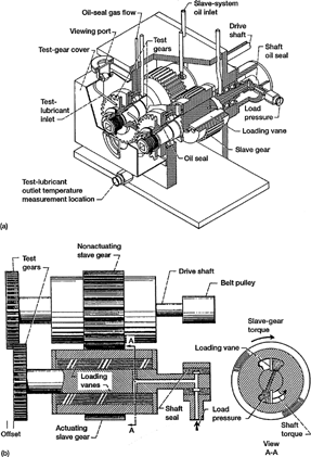
The loads on the test gears are provided using hydraulic pressure. A schematic of the apparatus is shown in . Oil pressure and leakage replacement flow are supplied to the load vanes through a shaft seal. As the oil pressure is increased on the load vanes located inside one of the slave gears, torque is applied to its shaft. This torque is transmitted through the test gears and back to the slave gears. In this way, power is circulated, and the desired load and corresponding stress level on the test gear teeth may be obtained by adjusting the hydraulic pressure. The two identical test gears may be started under no load, and the load can then be applied gradually. In order to enable testing at the desired contact stress, the gears are tested with the faces offset as shown in . By utilizing the offset testing arrangement for both faces of the gear teeth, a total of four surface fatigue tests can be run for each pair of gears.
Separate lubrication systems are provided for the test and slave gears. The two lubrication systems are separated at the gearbox shafts by pressurized labyrinth seals, with nitrogen as the seal gas. Inlet and outlet oil temperatures were continuously monitored. Cooled lubricant was supplied to the inlet of the gear mesh at 0.8 liter/min (0.2 gal/min) and 320 ± 7 K (116 ± 13°F). The lubricant outlet temperature was recorded and observed to have been maintained at 348 ± 4.5 K (166 ± 8°F). The lubricant was circulated through a 5 μm (200 μin.) nominal fiberglass filter to remove wear particles. For each test, 3.8 liter (1 gal) of lubricant was used.
The purpose of tests by Townsend and Shimski (Citation13) was to measure gear surface fatigue lives. A vibration transducer mounted on the gearbox was used to automatically stop the test rig when gear surface fatigue damage occurred. Surface fatigue damage caused an increase in the broadband (root-mean-squared magnitude) acceleration. The gearbox was also automatically stopped if there was a loss of oil flow to either the slave gearbox or the test gears, if the test gear oil overheated, or if there was a loss of seal gas pressurization.
Test Specimens
The test gears used for this work were manufactured from a single heat of consumable-electrode vacuum-melted (CVM) AISI 9310 steel. The gears were manufactured in two lots to the same specifications. The nominal chemical composition of the AISI 9310 material is given in . The gears were case carburized and heat treated according to . The nominal properties of the carburized gears were a case hardness of Rockwell C60, a case depth of 0.97 mm (0.038 in.), and a core hardness of Rockwell C38. The measured hardness profile of the gears is provided in . From , the hardness profile is considered to have not been changed significantly with running. Examined microstructure and typical residual stress profiles for such test gears have been reported (Townsend, et al. (Citation14), Krantz (Citation15)).
FIG. 2 Measured material hardness versus depth below the pitch-radius surface. Hardness values are converted from Knoop microhardness measurements.
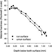
TABLE 1 Nominal Chemical Composition of AISI 9310 Gear Material
TABLE 2 Heat Treatment for AISI 9310 Gears
The dimensions for the test gears are given in . The gear pitch diameter was 89 mm (3.5 in.) and the tooth form was a 20° involute profile modified to provide a tip relief of 0.013 mm (0.0005 in.) starting at the highest point of single tooth contact. The gears have zero lead crowning but do have a nominal 0.13 mm (0.005 in.) radius edge break at the tips and sides of the teeth. The gear tooth surface finish after final grinding was specified as a maximum of 0.406 μm (16 μin.) rms. Tolerances for the gear geometries were specified to meet AGMA (American Gear Manufacturers Association) quality level class 12.
TABLE 3 Spur Test Gear Design Parameters; Gear Tolerances are Per AGMA Class 12
Test Procedure
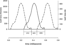
The test gears were cleaned to remove the preservative and assembled on the test rig. The test gears were run with the tooth faces offset by 3.3 mm (0.130 in.). All tests were run in at a load (tangent to the pitch circle) per unit face width of 123 N/mm (700 lb/in.) for one hour. The load was then increased to the test load of 580 N/mm (3300 lb/in.), which resulted in a 1.7 GPa (250 ksi) pitch-line maximum Hertz stress. The Hertz stress just stated is an idealized stress value assuming static equilibrium, perfectly smooth surfaces, and an even load distribution across a 2.79 mm (0.110 in.) line contact (the line length is less than the face width allowing for the face offset and the radius edge break). Typical dynamic tooth forces using the same rigs and gears of the same specification have been measured (Krantz (Citation15)), and the results are provided in . The tooth forces reported in are the dynamic forces normal to the tooth surface (or, in other words, tangent to the base circle) for a nominal pitch-line test load intensity of 580 N/mm (3,300 lb/in.). The static contact force (tangent to the base circle) used for stress calculations for such test load intensity was 1,720 N (387 lb). This value for the contact force is the value required for static torque equilibrium at the pitch point, and it is somewhat less than the measured typical dynamic forces.
FIG. 3 Measured dynamic tooth force at nominal test condition (Krantz (Citation15)). The solid line is the measured data, and the dashed lines are replicates of the measured data spaced along the ordinate at the equivalent of one tooth pitch. The zones of double tooth contact (DTC) and single tooth contact (STC) are illustrated.
The fatigue tests ran continuously and unattended (24 h/day). The test was stopped when the root-mean-squared acceleration level of the gearbox housing exceeded a limit. The gears were tested at 10,000 rpm, which gave a pitch-line velocity of 46.5 m/s (9,154 ft/min). If a gear pair operated for more than 500 hours (corresponding to 300 million stress cycles) without fatigue failure, the test was suspended.
The pitch-line elastohydrodynamic (EHD) film thickness was calculated using the rectangular conjunction formula of Dowson and Higginson (Citation16). For calculating the film thickness, it was assumed that the gear temperature was equal to the oil outlet temperature. The results of film thickness calculations and the values used for absolute viscosity and the pressure-viscosity coefficient are provided in . The lubricant properties used for EHD calculations are extrapolations using measured values for kinematic viscosity and typical values for specific gravity and pressure-viscosity coefficients at the test temperature (). Also provided in are specific film thickness (lambda ratio) values, calculated as the minimum film thickness divided by the initial specified composite surface roughness.
TABLE 4 Lubricant Properties
Measurement of Surface Profiles
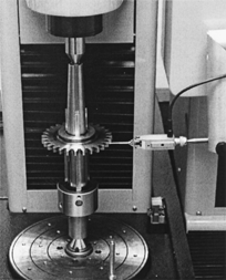
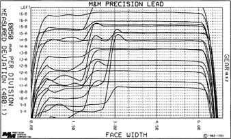
A gear coordinate measurement machine was used in this study to quantify the wear depths. shows the inspection machine used in this study while inspecting one of the test specimens. Two types of inspections were performed here. The first type of inspection used was a standard inspection as used by the gear industry. These inspections include the measurements of lead traces (from one side to the other at given constant radii) and involute traces (from the root to the tip of a tooth at given constant lead locations). In , results of such inspections of a new test specimen are shown. Here, four teeth at nearly 90 degree spacing were inspected. For each tooth inspected, two involute traces (traces A and B at one-third lead locations) and two lead traces (trace A in the addendum and trace B in the dedendum region) are shown in . It is evident from this figure that the profiles were machined very precisely with straight lead traces and a designed amount of tip relief. shows the lead charts for the teeth of a specimen at the end of its test. Since the actual contact occurred at the left portion of the face width only (due to face offset described earlier), the section to the right represents the unworn original tooth surface and the large step down to the left represents wear. It is obvious here that the wear magnitudes are rather significant and can be quantified by comparing the worn surface location (left) to the unworn surface location (right). It is also clear, and typical, that the wear amount is much larger in dedendum region (traces B) than that in addendum region (traces A).
FIG. 5 Involute and lead inspection charts of a typical new gear pair. Two lead and involute traces of both sides of teeth 1, 8, 15, and 22 are shown.
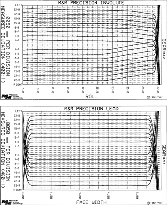
FIG. 6 A lead inspection chart of an example test specimen after the test was completed. Two traces of teeth 9 to 16 are shown. Only the face width plotted as (approximately) 0.00 to 3.00 mm was tested.
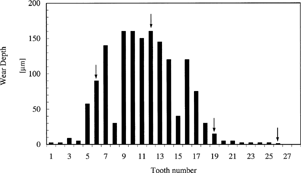
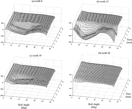
While standard inspections are useful to visualize the surface wear in any given direction (lead or involute), a large number of such traces are required to determine the maximum wear depth. For this purpose, the three-dimensional (3-D) topographical gear inspection method developed by Bajpai et al. (Citation10) was employed. When this method was applied to all the teeth of a test specimen, it was commonly observed that the maximum wear depth varied from tooth to tooth. In , a worn specimen that has a significant variation of maximum wear depths from tooth to tooth is shown. Here, a sinusoidal distribution of wear is evident. The maximum wear amount on tooth 27 is nearly zero while tooth 12 has nearly 160 μm maximum wear. shows the 3-D topographical inspections of four teeth of the same gear. Most of the gears had a more uniform wear distribution than shown by this extreme example illustrated in . Measuring the maximum wear amounts on all the teeth on all gears was considered to be excessively time consuming and hence not practical. In order to be able to represent the wear amount of a given gear by a single number, an average maximum wear parameter was defined as h = ¼(h
1 + h
8 + h
15 + h
22). In other words, the wear values of four equally spaced teeth (1, 8, 15, and 22) were used to define h. From the average maximum wear parameter h, the wear rate was defined as = h/C, where C is the recorded number of revolutions of the gear pair in millions (or millions of meshing cycles). For the majority of specimens, the value of C is equal to the measured surface fatigue life for the particular gear pair. For some specimens, C is the number of cycles completed without surface fatigue (the fatigue testing procedure made use of a nominal 300 million cycle limit to reduce the total test time for the fatigue life evaluations).
TEST LUBRICANTS
The lubricants used had been selected to study the effects of lubricants with similar base stocks but differing viscosities on the surface fatigue lives of AISI 9310 spur gears. Fatigue data were reported for seven lubricants (Townsend and Shimski (Citation13)) that were identified as lubricants A through G. For tests using lubricant F, there were insufficient numbers of tested gears available for wear measurements, so lubricant F was not included as part of the present study. Subsequent to publication, Townsend and Shimski (Citation13) conducted additional tests using other lubricants. Although these fatigue data have not yet been published, the test results, records, and some of the specimens were available to the present investigators. For the present wear study, gear specimens tested using a lubricant designated as H in this article were analyzed for wear.
Properties of the lubricants studied are provided in , and descriptions of the lubricants follow. Lubricant A is an unformulated base stock lubricant with no additives, and it has a viscosity between that required for the MIL-L-7808J and MIL-L-23699 specifications. Lubricant B is a 5 cSt lubricant meeting the MIL-L-23699 specification, and it has a small amount of boundary lubrication additive. Lubricant C is a 3 cSt lubricant meeting the MIL-L-7808J specification. Lubricant C has the lowest viscosity of all the lubricants included in the study, and it has a proprietary extreme pressure additive package. Lubricants D and H are lubricants developed for helicopter gearboxes, and both lubricants meet the DOD-L-85734 specification. Lubricants D and H are 5 cSt lubricants with extreme pressure additive packages, and these two lubricants were obtained from two different manufacturers. Lubricant E is a 7.5 cSt lubricant with an extreme pressure additive, and this lubricant meets the development specification DERD-2487. Lubricant G is a 9 cSt base stock industrial grade lubricant. Six of the seven lubricants included in this study could be classified as synthetic polyol-ester base stock lubricants. Lubricant E is a polyalkylene-glycol base stock with a small amount of boundary lubricant additive.
RESULTS AND DISCUSSION
Amounts and Descriptions of Wear
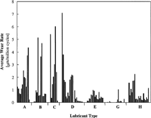
A total of 112 gear specimens were inspected using a gear coordinate measuring machine to evaluate the average wear depth and wear rate using the methodology described above. The number of samples for each lubricant test population was dependent on the availability of the test specimens. Gears tested with lubricant C had the lowest number of samples, N = 8, and gears tested with lubricant H had the largest number of samples, N = 23. Four teeth on each gear specimen were inspected (a total of 448 teeth), and wear amounts were averaged to determine the average wear rate for each gear. summarizes the measured wear amounts and wear rates (mean and standard deviation values) and the sample sizes for each lubricant. The amount of scatter of the wear data from gear specimen to specimen is quite significant. The distribution of wear rates is illustrated in . From and , it is clear that lubricant C resulted in the most severe wear rates while lubricant G performed the best. Other lubricants resulted in levels of wear between these extremes.
TABLE 5 Wear Amount, h, and Wear Rate,  , Parameters for the Seven Test Lubricants
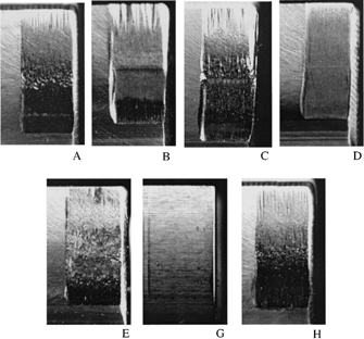
To help document and characterize the wear, photos of worn gear teeth, one for each lubricant tested, are provided in . In general, the wear can be described as a mild, polishing wear over most of the tooth profile. Near the start and end of contact, there exists some evidence of abrasive and/or light adhesive wear (scoring-like marks). In general, the scoring-like marks that appeared at the positions of high sliding tended to be less severe for lubricants with higher viscosities. It is evident that lesser wear amounts occurred near the pitch line where sliding velocities are small as compared to the roots and tips of the teeth. The worn surfaces in some cases were remarkable in that worn and very smooth regions can be found a slight distance from the pitch point while the grinding patterns were still visible at the pitch point. The photograph for the tooth tested with lubricant G demonstrates that for this lubricant and for the chosen test conditions, the working surfaces were well protected with few direct asperity contacts and, for practical purposes, nearly zero wear.
The maximum wear depths invariably occurred in the dedendum region of the teeth; that, is somewhat below the pitch line. In the regions of maximum wear depth, the worn surfaces have a worked and polished appearance. Any scratching marks in the direction of sliding that were present in this region of maximum wear can be characterized as minor scratching consistent with abrasive wear. There was no evidence of destructive scoring (scuffing), spalling, pitting, or micropitting (grey-staining) failures on the teeth selected for wear measurements. Some teeth on the gears had surface fatigue damage (the intent of the original study by Townsend and Shimski (Citation13)), but care was taken to select teeth without such damage for measurements of wear. Illustrations of teeth with surface fatigue damage for these tests were provided by Townsend and Shimski (Citation13).
Influence of Lubricant Type on Gear Wear
To characterize differences in wear owing to different lubricants, wear rates are plotted as a function of key lubrication parameters. shows as a function of the absolute viscosity of the lubricants at the testing temperature as listed in . It is clear from this figure that the wear rates are an inverse function of the viscosity of the lubricant. C has the lowest viscosity (0.010 N-s/m2), resulting in the most severe wear rate of nearly 2.6 μm per million cycles, while lubricant G with the highest viscosity value (0.028 N-s/m2) resulted in the lowest wear rate of about 0.11 μm per million cycles. The other lubricants generally are ordered in sequence relative to their viscosity values. From , the lubricants B, D, and H have differing wear rates but similar viscosity values. It is perhaps significant that lubricant B meets the specification MIL-L-23699 (turbine engine lubricants), while lubricants D and H meet the specification DOD-L-85734 (helicopter transmission lubricants). One might expect lubricants D and H, developed for gearing, to perform better than lubricant B in a gear test. This scatter in the wear results for lubricants B, D, and H (in spite of nearly equal viscosities) highlights that lubricant composition and additive packages, along with viscosity, strongly influence a lubricant's capability for wear protection.
FIG. 11 Variation of average wear rate as a function of viscosity at the testing temperature for each lubricant. The solid line is a trend line representing a quadratic curve fit.
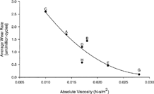
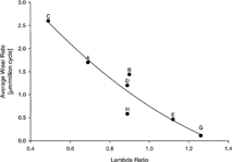
A very similar behavior is observed when is plotted as a function of the lambda ratio that is defined as the ratio of central film thickness (determined by using the smooth surface elastohydrodynamic lubrication [EHL] formulas of Dowson and Higginson (Citation16) to the initial specified composite surface roughness of mating gear surfaces. The specified root-mean-square roughness of 0.4 μm results in a composite roughness of about 0.57 μm. In , the relative ranking of the test lubricants for their wear performance remains inversely proportional to the lambda ratio (the same order as ). Lubricant C, having the lowest viscosity, results in a very thin film and a very low lambda ratio (about 0.49) as listed in . As a result, mixed lubrication conditions with significant asperity interactions occurred, along with extensive wear. The opposite is true for lubricant G, which allows a relatively large lambda ratio of 1.26, minimizing the amount of surface wear. Other lubricants are ordered between these two extremes, depending on the lambda ratio.
Wear versus Contact Fatigue Life
The gear fatigue experiments that were conducted by Townsend and Shimski (Citation13) established and quantified the influence of lubricant viscosity on gear surface fatigue lives. The surface fatigue life results are summarized in . The table is sorted by the measured 10 and 50% lives. These percentile life estimates were determined by modeling the life dispersions as Weibull distributions and employing the regression methods of Johnson (Citation17) to determine the values for the Weibull slope and scale parameters. In , estimated 10 and 50% surface fatigue lives corresponding to each lubricant are plotted against the viscosity of the lubricant. The results demonstrate that, in general, the greater the viscosity of the lubricant the longer the surface fatigue lives. The solid lines in represents exponential relationships observed as linear lines since the surface fatigue lives are displayed using a log scale.
FIG. 13 Variation of surface fatigue life as a function of viscosity of each lubricant. The solid lines are trends representing exponential curve fits at 10% population failed and 50% population failed.
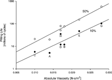
TABLE 6 Surface Fatigue Test Results (Townsend and Shimski (Citation13))
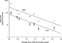
From , it is evident that the lubricant viscosity has a similar trend for both surface fatigue life and wear. For the lubricants tested here, the larger the viscosity of the lubricant the longer the fatigue lives and smaller the wear amounts. In , the fatigue lives and wear rates for each lubricant group are plotted to show the correlation. The relationship between the wear rates and surface fatigue lives is exponential. This correlation highlights the dominant role of the lubricant viscosity. The relationship depicted in shows that a lubricant that functioned well in terms of surface fatigue life also tended to function well in terms of wear. Likewise, it can be stated that very low wear rates indicate a relatively favorable lubrication condition that also tended to promote long surface fatigue life. Finally lubricants with nearly equal viscosity but differing additives offer differing levels of protection for wear and surface fatigue.
CONCLUSION
In this study, the influence of lubricant viscosity and additives on the wear rate of spur gear pairs was investigated experimentally. The gear specimens from a comprehensive gear durability test program that includes seven different lubricants were inspected to demonstrate the influence of the lubrication condition on gear tooth surface wear. The results indicate that the wear rates are strongly related to the viscosity of the lubricant. Lubricants with larger viscosity result in larger lambda ratios and lower wear rates. A similar strong influence of the lubricant viscosity was previously observed for surface fatigue lives as well. An exponential relationship between the surface fatigue lives and the average wear rates was found. The data suggest that viscosity plays a dominant role. There were also considerable differences in wear amounts for three lubricants with differing additive packages but similar compositions and viscosities.
ACKNOWLEDGMENTS
The authors thank Mr. Gurinder Singh for measuring the gear surfaces and for processing the data to determine wear amounts. They also thank M&M Precision Systems Inc. for making the gear coordinate measurement machine available.
Manuscript received by STLE June 16, 2003 Final manuscript approved October 22, 2003 Review led by Bob Errichello
Notes
a Data used for film thickness calculations.
b Lambda ratio = calculated minimum film thickness/initial composite surface roughness.
c Basestock oil.
REFERENCES
- Choy , F. K. , Polyschuk , V. , Zakrajsek , J. J. , Handschuh , R. F. and Townsend , D. P. 1996 . “Analysis of the Effects of Surface Pitting and Wear on the Vibration of a Gear Transmission System” . Tribol. Int. , 29 : pp 77 – 83 .
- Mackaldener , M. , Flodin , A. and Andersson , S. 2001 . “Robust Noise Characteristics of Gears Due to Their Applications, Manufacturing Errors and Wear” . In JSME International Conference on Motion and Power Transmission, MPT 2001 21 – 26 . Fukuoka, , Japan
- Kuang , J. H. and Lin , A. D. 2001 . “The Effect of Tooth Wear on the Vibration Spectrum of a Spur Gear Pair” . J. Vib. Acoust. , 123 : pp 311 – 317 .
- Chen , Y. and Matubara , M. 2001 . “Effect of Automatic Transmission Fluid on Pitting Fatigue Strength of Carburized Gears” . In JSME International Conference on Motion and Power Transmission, MPT 2001 151 – 156 . Fukuoka, , Japan
- Cioc , C. , Cioc , S. , Kahraman , A. and Keith , T. G. 2002 . “A Deterministic Elastohydrodynamic Lubrication Model of High-Speed Transmission Components” . Tribol. Trans. , 45 : pp 556 – 562 .
- Shifeng , W. and Cheng , H. S. 1993 . “Sliding Wear Calculation in Spur Gears” . J. Tribol. , 115 : pp 493 – 503 .
- Flodin , A. and Andersson , S. 1997 . “Simulation of Mild Wear in Spur Gears” . Wear , 207 : pp 123 – 128 .
- Flodin , A. and Andersson , S. 2000 . “Simulation of Mild Wear in Helical Gears” . Wear , 241 : pp 123 – 128 .
- Flodin , A. and Andersson , S. 2001 . “A Simplified Model for Wear Prediction in Helical Gears” . Wear , 249 : pp 285 – 292 .
- Bajpai , P. , Kahraman , A. and Anderson , N. 2003 . “Development of Surface Wear Model for Helical Gear Pairs,” . J. Tribol. , In review
- Archard , J. F. 1953 . “Contact of Rubbing Flat Surfaces” . J. Appl. Phy. , 24 : pp 981 – 988 .
- Challen , J. M. and Oxley , P. L. B. 1986 . “Prediction of Archard's Wear Coefficient for Sliding Metallic Sliding Friction Assuming Low Cycle Fatigue Wear Mechanism” . Wear , 111 : pp 275 – 288 .
- Townsend , D. P. and Shimski , J. 1994 . “Evaluation of the EHL Film Thickness and Extreme Pressure Additives on Gear Surface Fatigue,” NASA TM-106663
- Townsend , D. P. , Chevalier , J. L. and Zaretsky , E. V. 1973 . “Pitting Fatigue Characteristics of AISI M-50 and Super Nitralloy Spur Gears,” NASA TN D-7261
- Krantz , T. L. 2002 . “The Influence of Roughness on Gear Surface Fatigue,” , Cleveland, Ohio : Case Western Reserve University . Ph.D. diss.
- Dowson , D. and Higginson , G. 1966 . Elasto-Hydrodynamic Lubrication , New York : Pergamon Press .
- Johnson , L. 1964 . The Statistical Treatment of Fatigue Experiments , New York : Elsevier .
