Abstract
A detailed journal bearing analysis for accurate evaluation of film dynamic characteristics is presented. The new formulation is based on a local perturbation of the oil film at each computational node that captures the important effects of journal misalignment and bearing structural deformation in rotor dynamics and engine NVH applications. The new algorithm is an extension to the classical approach of evaluating film dynamic characteristics based on journal eccentricity perturbation. The governing equations for the oil film pressure, stiffness, and damping are solved using a finite difference approach and their output is validated with numerical results from the literature.
NOMENCLATURE
| B | = |
damping coefficient |
| C | = |
damping matrix |
| c | = |
radial clearance |
| F | = |
load vector |
| h | = |
oil film thickness distribution |
| K | = |
stiffness matrix |
| L | = |
bearing length |
| N | = |
number of mesh nodes |
| P | = |
oil film hydrodynamic pressure |
| R | = |
journal radius |
| W | = |
applied load |
| z | = |
crankshaft axial direction |
| Γ | = |
oil film domain |
|
| = |
small perturbation in film thickness squeeze |
| Δx,Δy | = |
mesh dimension, perturbation in journal position |
| θ | = |
circumferential direction |
| μ | = |
lubricant viscosity |
| ψ x ,ψ y | = |
normalized shaft tilt around x- and y-axes |
| ω | = |
angular velocity |
Superscripts
| e | = |
equivalent |
Subscripts
| o | = |
original; equilibrium condition |
INTRODUCTION
One of the critical elements in accurate simulation of rotor dynamics systems is the flexibility of bearing support. With journal bearings, the shaft tilting and bending as well as the bearing housing deformation become especially important since they greatly affect the oil film distribution and, therefore, the bearing dynamic characteristics. The journal misalignment and bearing structural deformation effects can be very important in accurately assessing the crankshaft-block dynamic interaction of an internal combustion (I.C.) engine or rotor dynamic behavior.
The journal bearing lubrication problem has been extensively studied over the past forty years. Among the first studies are those using the mobility method (Booker (Citation1), (Citation2)). It is widely used for crankshaft and connecting rod bearings due to its simplicity and computational efficiency for dynamically loaded bearings. However, it assumes circumferential bearing symmetry, neglecting, therefore, the important effects of journal misalignment and bearing geometric attributes such as oil grooves and oil holes. Very accurate but computationally intensive algorithms are presented in Goenka (Citation3), (Citation4); Kumar and Booker (Citation5) for rigid bearing surfaces. A significant amount of work has also been reported in the area of elastohydrodynamic (EHD) analysis of connecting rod bearings (Goenka and Oh (Citation6); McIvor and Fenner (Citation7); Kumar, et al. (Citation8); Boedo, et al. (Citation9); Knoll, et al. (Citation10)), which considers the elastic deformation of the bearing housing. The bearing structural deformation is obtained by a conventional structural finite element analysis or as a linear superposition of selected bearing mode shapes. However, all of these methods are computationally intensive and therefore not practical for crankshaft-block dynamic interaction studies.
The journal bearing flexibility can play an important role in rotor dynamics. The subject of the dynamic characteristics of fluid film bearings has been studied extensively. In the classic article by Lund and Thomsen (Citation11), the fluid film stiffness and damping coefficients were calculated numerically for rigid journal bearings with no journal misalignment in order to understand the effects of hydrodynamic film stiffness on the stability of the rotors. Theoretical and experimental investigations were conducted in Parkins (Citation12), (Citation13) on the nonlinear fluid film dynamic coefficients. It was found that radial flexibility of the oil film has significant influence on rotor dynamics. A study of the film stiffness and damping coefficients for mechanical face seals considering three degrees of freedom for the seal ring is presented in Green and Etison (Citation14). The assumption of small perturbation was used. An experimental estimation of the dynamic characteristics of a journal bearing is reported in Chang and Zheng (Citation15), which emphasizes the importance of accurate dynamic characteristics in the operational performance of high-speed rotational machines. In Subbiah, et al. (Citation16) the dynamic coefficients are expressed with more than two degrees of freedom in an attempt to account for the important effect of journal misalignment in rotor bearing systems. The difficulty of accurately estimating the dynamic coefficients at high eccentricity ratios was pointed out.
The potential inaccuracies in calculating the dynamic coefficients using the ratio of pressure change due to a film thickness change are reported in Klit and Lund (Citation17). The alternative and more accurate method of a linear perturbation of the Reynolds equation was first introduced in the same study. A brief review of the journal bearing dynamic coefficient concept is presented in Lund (Citation18). The perturbation of the Reynolds equation was recommended in order to include effects of elastic deformation of the bearing housing and manufacturing tolerances of the supporting bearing clearances. The combustion excitation of an internal combustion engine was identified as the major source of engine noise and vibration in Nefske and Sung (Citation19). Since the combustion excitation is transferred from the crankshaft to the engine block through the bearing fluid film, the dynamic characteristics of the bearings are therefore very important in predicting engine Noise-Vibration-Harshness (NVH).
Inaccuracies in the experimental measurements of the dynamic coefficients have been reported in Lund (Citation18) and Kostrzewsky and Flack (Citation20). The challenges in acquiring accurate measurements of the dynamic coefficients were addressed as a possible source of frequently reported discrepancies between numerical and experimental values. These discrepancies were also attributed to the fact that the dynamic coefficients cannot be measured directly but instead must be derived from a series of other measurements, which are often dependent on test conditions. A Rayleigh-Ritz method was used in Kato and Hori (Citation21) to obtain the dynamic coefficients of a journal bearing with finite length. The hydrodynamic pressure distribution was approximated using orthogonal functions. The calculation was limited to two degrees of freedom. The work in Knoll and Peeken (Citation22) considered the lubricant film as an elastic layer with physical properties different from the mating surfaces, as dictated by the Reynolds equation. The justification for this approach was made based on insufficient convergence exhibited by the iterative methods at high load and high structural deformations. Based on the existing literature on the dynamic fluid film characteristics, it is evident that most studies are limited to a few degrees of freedom. Seldom do researchers include more degrees of freedom to accurately capture effects such as journal misalignment (Pafelias (Citation23); Pafelias and Broniarek (Citation24); Nikolakopoulous and Papadopoulos (Citation25)).
A recent publication by Kakoty and Majumdar (Citation26) on the fluid film dynamic characteristics presents a study of the fluid inertia effect on the stability of a finite journal bearing operating with a low viscosity lubricant under high speed. A linear perturbation technique was used to evaluate dynamic characteristics of the journal bearing in two dimensions. A non-Newtonian lubricant was used in Lin (Citation27) to study the stiffness and damping characteristics in the presence of oil additives. A free boundary theory was used in Zheng and Hasebe (Citation28) to obtain the film dynamic coefficients of the journal bearing in two dimensions. The resulting dynamic coefficients were in good agreement with Lund and Thomson (Citation11). An analytical expression for the film dynamic characteristics is presented in Rao, et al. (Citation29) based on a combination of short and long bearing approximations. Despite recent contributions to the subject of the film dynamic coefficients, the calculation methods are mostly limited to two degrees of freedom and cannot be utilized to address journal misalignment and bearing structural deformation. These effects are of extreme importance in internal combustion engines, where the crankshaft undergoes significant deformation due to the combination of inertia and combustion loading. In addition, the inclination and deformation of the bearing caps in a running engine as reported in Aayama, et al. (Citation30) further calls for an accurate bearing lubrication module capable of handling structural deformations.
In the present article, a detailed journal bearing elastohydrodynamic analysis for accurate evaluation of the oil film dynamic characteristics is presented. The governing differential equations are derived using a general formulation with no limitation imposed on the bearing structural and elastic behavior. The new formulation utilizes a local perturbation of the film at each computational node instead of a journal eccentricity perturbation, which is commonly used. The proposed approach is general enough to capture the important effects of bearing housing deformation and journal misalignment/bending in rotor dynamics and engine NVH applications. The governing equations for oil film pressure, stiffness, and damping characteristics are discretized using a finite difference method and solved over a rectangular mesh of the oil film domain using a Successive Over Relaxation (SOR) algorithm. For computational efficiency without loss of accuracy, the “Influence Zone” concept (Ebrat (Citation31)) and a diagonalization procedure of the oil film stiffness and damping matrices are introduced. The developed approach is ideal for detailed rotor dynamics or engine dynamic crankshaft-block interaction studies with flexible crankshaft and block structures (Ebrat, et al. (Citation32)).
BEARING LUBRICATION ANALYSIS
This section presents an overview of the Reynolds equation and the appropriate boundary conditions for calculating the oil film pressure in a journal bearing. The perturbation of the Reynolds equation is presented for deriving the corresponding equations for the oil film stiffness and damping matrices. These equations are subsequently solved using a finite difference formulation.
Reynolds Equation
The oil film pressure distribution in journal bearings is described by the Reynolds equation, which is derived from the Navier-Stokes equations for incompressible flow and the continuity equation under simplifying assumptions (Pinkus and Sternlicht (Citation33)). For a Newtonian fluid, the Reynolds equation is written as
There is a prescribed pressure at the two bearing ends along the oil grooves. EquationEq. [1] can be discretized and solved numerically for the hydrodynamic pressure field subject to the imposed pressure boundary conditions. A cavitation boundary condition must also be used. There are many cavitation conditions used in the literature (Mourelatos (Citation34)). The simplest of those are the Half-Sommerfeld boundary condition and the Gümble boundary condition, which simply neglects negative pressure values. A more accurate cavitation condition is the Reynolds boundary condition, which ensures mass flow conservation at the rupture boundary but not at the reformation boundary (Frene (Citation35); Paranjpe and Goenka (Citation36)). The most accurate cavitation boundary condition is the Jakobsson-Floberg-Olsson (JFO) condition. It ensures oil mass conservation at both film ruapture and reformation boundaries (Frene (Citation35); Paranjpe and Goenka (Citation36)). Comparisons between the Reynolds and JFO conditions have shown that the former is adequate for bearing load capacity calculations while the latter is needed for predicting the oil flow in the bearing (Paranjpe and Goenka (Citation36)). For system level problems, such as engine crankshaft-block dynamic interaction or rotor dynamic studies, the lubrication algorithm is repeatedly called in the computational process, therefore increasing the computational cost considerably. In such cases, the Gümble or Reynolds conditions are the best compromise between accuracy and efficiency. The current work uses the Reynolds cavitation condition.
Perturbation of Reynolds Equation
For a journal bearing rotating at constant speed, the hydrodynamic pressure is a function of the local film thickness and its rate of change
, i.e.,
Alinear perturbation approach is used to solve EquationEq. [1]. At each time step, the film thickness and squeeze film thickness distributions are assumed equal to
Under the assumption of small perturbation values for and
, EquationEq. [1] yields (Citation31) the following perturbed Reynolds equation:
Separation of variables results in the following expanded equations (Ebrat (Citation31)):
EquationEquations [7], [8], and [9] constitute the governing equations for the hydrodynamic oil film pressure distribution, stiffness matrix, and damping matrix, respectively. Since there is no closed form solution, they will be solved numerically using a finite difference method.
FINITE DIFFERENCE FORMULATION
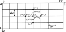
A finite difference formulation is developed in this section for solving the governing EquationEqs. [7], [8], and [9] for the oil film pressure, stiffness, and damping, respectively, in a computationally efficient and yet accurate fashion. The oil film domain is represented by a two-dimensional finite difference mesh as shown in . The derivatives in the governing differential equations are approximated by differential formulae. In contrast to the finite element method, it is not necessary to generate a global fluidity matrix or use a local coordinate system and a coordinate transformation.
The first-order derivatives in the left-hand side of the governing equations are evaluated at the midpoints between existing nodes as shown in for minimum discretization error.
The finite difference approximations of different terms in EquationEq. [7] are (Ebrat (Citation31)):
Similarly, the SOR method formulations for the oil film stiffness and damping are
EquationEquations [11], [14a], and [15] are solved iteratively using an efficient SOR procedure. Starting with the pressure distribution of the previous time step, convergence for the current time step is normally reached within a few iterations. An over relaxation parameter, β within the range of (1.40-1.75) is used (Press, et al. (Citation37)). The lubrication boundary conditions such as oil groove pressure and bearing edge pressure are imposed efficiently during the iterative procedure. If N nodes are used to discretize the oil film domain, the explicit form of the resulting stiffness matrix is
A similar explicit form holds for the damping matrix [C]. The ij element of the stiffness (damping) matrix represents the pressure change in node i due to a unit oil film thickness (squeeze film velocity) change at node j. Note that each column of the stiffness (damping) matrix of EquationEq. [16] requires a mesh-wide stiffness (damping) evaluation for the oil film thickness (squeeze film velocity) perturbation of the corresponding node. This operation greatly dominates the overall computational effort in rotor dynamics applications due to the coupling of the shaft dynamic equations with the main bearing elastohydrodynamic behavior. For this reason, the concept of “Influence Zone” is proposed (Ebrat (Citation31)) for further improving the computational efficiency without loss of accuracy. The “Influence Zone” concept is based on the observation that nodes located away from the perturbed node do not exhibit a significant pressure change. An “Influence Zone” area is therefore defined by a certain number of neighboring nodes around the perturbed node in the circumferential direction. The evaluation of the mesh-wide stiffness and damping coefficients due to a perturbed node is limited to the nodes within the “Influence Zone.” The SOR solver in the finite difference formulation considers only the nodes within the “Influence Zone.” The computational efficiency gains are demonstrated in Ebrat (Citation31).
DIAGONALIZATION OF OIL FILM STIFFNESS AND DAMPING MATRICES
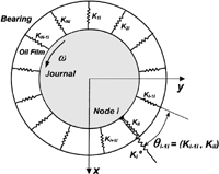
In rotor dynamic systems, the shaft dynamic equations are coupled with the main bearing elastohydrodynamic characteristics through large, fully populated stiffness and damping matrices (EquationEq. [16]). The size of the oil film stiffness and damping matrices is usually very large in order to accurately capture the highly nonlinear oil film pressure distribution, particularly for high journal eccentricity and journal misalignment conditions. To further reduce the computational effort, a diagonalization of the oil film stiffness and damping matrices is also proposed (Ebrat (Citation31)) by lumping the off-diagonal terms into an “equivalent” diagonal term for each node of the lubrication mesh. This reduces the computational cost substantially with minimal loss of accuracy. This section describes the oil film stiffness and damping diagonalization procedure.
A small oil film thickness change δ i for the ith node of an N-node lubrication mesh results in a pressure change Δ P i as
Each term in EquationEq. [18], if multiplied by a unit area, represents a radial force. Projection of these forces to the radial direction of node i and elimination of the arbitrary oil film perturbation δ i yields
A similar expression holds for the equivalent diagonalized damping matrix.
VALIDATION RESULTS
The journal bearing misalignment due to shaft tilting and bending and the bearing housing flexibility (EHD effect) can play a very important role in rotor dynamic applications. Accurate solution of rotor dynamic problems involving journal bearings requires a detailed calculation of the oil film dynamic coefficients. With the presence of housing deformation, the conventionally used shaft eccentricity and tilt angle are no longer sufficient to describe the oil film distribution. A linear perturbation of only the shaft eccentricity and tilt angle is not enough to capture the full bearing dynamic characteristics. Instead, as presented in this article, a local perturbation of the oil film at each node of the discretized oil film domain is necessary. For validating the proposed method, a simplified version of the present formulation for rigid bearing dynamic characteristics, with and without journal misalignment, is described in this section and results are compared with Lund and Thomsen (Citation11) and Pafelias (Citation23).
Rigid Bearing Dynamic Characteristics without Misalignment
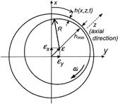
To validate the present work, the journal bearing dynamic coefficients in Lund and Thomsen (Citation11) are first considered for the special case of rigid bearing housing with no journal misalignment. Our analysis is slightly modified to reflect the rigid bearing assumption used in Lund and Thomsen (Citation11). In the absence of housing deformation and journal misalignment, the oil film distribution depends only on the journal eccentricities in the vertical (x) and lateral (y) directions (see ). A first-order perturbation of the oil film thickness h 3, squeeze film velocity, and pressure distribution around their nominal values, denoted by the subscript “o,” yields
Note that x = Rθ. Substitution of EquationEqs. [21] and [22] in EquationEq. [1] and use of the approximation
Separation of variables due to the arbitrary small perturbations Δ
x
, Δ
y
, , and
yields the following equations:
EquationEquations [27a-e] are solved for P
o
, P
x
= ∂ P/∂ x, P
y
= ∂ P/∂ y, P
= ∂ P/∂
, and P
= ∂ PO/∂
, respectively. After a finite difference formulation similar to that presented, the following equations are first formed and then solved using the SOR method:
During the iterative solution of EquationEq. [28], the Reynolds cavitation condition is used at the film rupture zone. Also, a constant pressure is enforced along the bearing edges and over the oil grooves.
After EquationEq. [28] is solved for P = P
o
, P
x
, P
y
, ,
, the stiffness coefficients are calculated by integrating over the oil domain as follows:
Similar expressions hold for the damping coefficients B
xx
, B
yx
, B
xy
, and B
yy
in which the pressure derivatives are with respect to and
.
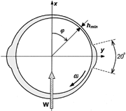
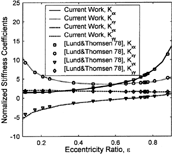
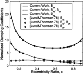
A bearing with two axial grooves as shown in and length-to-diameter ratio (L/D) = 0.5 is used to compare the results from the present analysis with those in Lund and Thomsen (Citation11).
compare the normalized stiffness and damping coefficients and
respectively, where c, ω, and W are the bearing radial clearance, rotational speed, and load. An excellent agreement is observed between the present analysis and Lund and Thomsen (Citation11) throughout the entire eccentricity ratio range.
Rigid Bearing Dynamic Characteristics with Misalignment
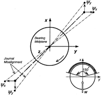
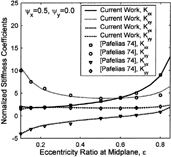
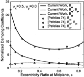
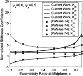
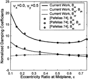
Further validation is presented for misaligned journals, based on results reported in reference (Citation23). The misalignment is introduced using shaft tilting around the x- and y-axes as shown in . The results are presented for a normalized misalignment angle of ψ
x
= 0.5 and ψ
y
= 0.5. The normalized misalignment is defined as ψ = around the bearing midplane (), where c and L are the bearing radial clearance and length, respectively. A partial, 150-degree bearing loaded in x-direction is used.
As shown in , there is an excellent agreement between the present method and the results reported in reference (Citation23) for the entire eccentricity range. present the comparison for a journal tilt perpendicular to the direction of the applied load. compare the results for a journal tilt in the direction of the applied load.
SUMMARY AND CONCLUSIONS
A detailed and efficient journal bearing hydrodynamic analysis of the oil film dynamic characteristics was developed based on a finite difference formulation. The analysis can be used in rotor dynamic applications as well as engine dynamic crankshaft-block interaction studies with flexible crankshaft and block structures. A perturbation approach on the Reynolds equation was employed in calculating the oil film pressure distribution and the bearing dynamic stiffness and damping matrices. The bearing dynamic characteristics are based on perturbations of each node of the oil film domain, therefore accounting for the effects of local bearing structural deformation (EHD) and journal tilting and bending. In the developed analysis, the oil film domain is discretized using a rectangular two-dimensional finite difference mesh. The finite difference equations are solved using a Successive Over Relaxation (SOR) algorithm. For computational efficiency, the concept of “Influence Zone” and a diagonalization procedure of the fully populated oil film stiffness and damping matrices are introduced. The proposed method was validated with numerical results from the literature. Excellent agreement was observed.
ACKNOWLEDGMENT
This research was supported by Federal-Mogul Corporation. The financial support is gratefully acknowledged.
Presented at the STLE/ASME Tribology Conference in Ponte Vedra Beach, Florida October 27-29, 2003 Final manuscript approved September 3, 2003 Review led by Henry Sneck
REFERENCES
- Booker , J. F. 1965 . “Dynamically Loaded Journal Bearings: Mobility Method of Solution” . Trans. ASME J. Basic Eng. , 87 : pp 537 – 546 .
- Booker , J. F. 1971 . “Dynamically-Loaded Journal Bearings: Numerical Application of the Mobility Methods” . Trans. ASME J. Lubr. Technol. , 93 ( 1 ) : pp 168 – 176 .
- Goenka , P. K. 1984 . “Dynamically Loaded Journal Bearings: Finite-Element Method Analysis” . Trans. ASME J. Tribol., Series F , : pp 429 – 439 .
- Goenka , P. K. and Paranjpe , R. S. 1992 . “A Review of Engine Bearing Analysis Methods at General Motors,” , SAE Publication, SP-919 67 – 75 . on Engine Tribology, SAE Paper No. 920489
- Kumar , A. and Booker , J. B. 1994 . “A Mass and Energy Conserving Finite Element Lubrication Algorithm” . Trans. ASME J. Tribol. , 116 : pp 667 – 671 .
- Goenka , P. K. and Oh , K. P. 1986 . “An Optimum Short Bearing Theory for the Elastohydrodynamic Solution of Journal Bearings” . Trans. ASME J. Tribol. , 108 : pp 294 – 299 .
- McIvor , J. D. and Fenner , D. N. 1989 . “Finite Element Analysis of Dynamically Loaded Flexible Journal Bearings: A Fast Newton-Raphson Method” . Trans. ASME J. Tribol. , 111 : pp 597 – 604 .
- Kumar , A. , Goenka , P. K. and Booker , J. B. 1990 . “Modal Analysis Elastohydrodynamic Lubrication: A Connecting Rod Application” . Trans. ASME J. Tribol. , 112 ( 3 ) : pp 524 – 534 .
- Boedo , S. , Booker , J. F. and Wilkie , M. J. 1995 . “A Mass Conserving Modal Analysis for Elastohydrodynamic Lubrication” . In Lubricants and Lubrication , Edited by: Dowson , D. Amsterdam, , Netherlands : Elsevier .
- Knoll , G. , Lang , J. and Reinaecker , A. “Transient EHD Connecting Rod Analysis: Full Dynamic versus Quasi-static Deformation” . Proc. of the Joint ASME/STLE Tribol. Conf. October 8–11 , Orlando, Fla.
- Lund , J. W. and Thomsen , K. K. 1978 . “A Calculation Method and Data for the Dynamic Coefficients of Oil-Lubricated Journal Bearings” . In Topics in Fluid Film Bearing and Rotor Bearing System Design and Optimization , New York : ASME .
- Parkins , D. W. 1979 . “Theoretical and Experimental Determination of the Dynamic Characteristic of a Hydrodynamic Journal Bearing” . J. Lubr. Technol. , 101 : pp 129 – 139 .
- Parkins , D. W. 1981 . “Measured Characteristic of a Journal Bearing Oil Film” . Trans. ASME , 103 : pp 120 – 125 .
- Green , I. and Etsion , I. 1983 . “Fluid Film Dynamic Coefficients in Mechanical Face Seals” . J. Lubr. Technol. , 105 : pp 297 – 302 .
- Chang , C. and Zheng , P. 1985 . “Experimental Determination of the Stiffness and Damping Coefficients of Fluid Film Bearings by Means of Step Forces” . Tribol. Int. , 18 ( 2 ) : pp 81 – 91 .
- Subbiah , R. , Bhat , R. B. and Sankar , T. S. 1985 . “Rotational Stiffness and Damping Coefficients of Fluid Film in a Finite Cylindrical Bearing” . ASLE Trans. , 29 ( 3 ) : pp 414 – 422 .
- Klit , P. and Lund , J. W. 1986 . “Calculation of the Dynamic Coefficients of a Journal Bearing Using a Variational Approach” . Trans. ASME J. Tribol. , 108 : pp 421 – 425 .
- Lund , J. W. 1987 . “Review of the Concept of Dynamic Coefficients for Fluid Film Journal Bearings” . Trans. ASME J. Tribol. , 109 : pp 37 – 41 .
- Nefske , D. J. and Sung , S. H. 1989 . “Coupled Vibration Response of the Engine Crank-Block System” . ASME Publication DE , 18 ( 4 ) : pp 379 – 385 .
- Kostrzewsky , G. J. and Flack , R. D. 1990 . “Accuracy Evaluation of Experimentally Derived Dynamic Coefficients of Fluid Film Bearings, Part I: Development of Method” . Tribol. Trans. , 33 : pp 105 – 114 .
- Kato , T. and Hori , Y. 1988 . “A Fast Method for Calculating Dynamic Coefficients of Finite Width Journal Bearings with Quasi Reynolds Boundary Condition” . Trans. ASME J. Tribol. , 110 : pp 387 – 393 .
- Knoll , G. and Peeken , H. 1990 . “FEM Formulation of Fluid Contact Elements for Elastohydrodynamic Structure Interaction” . Proc. of the Japan Int. Tribol. Conf., Nagoya, Japan ,
- Pafelias , T. A. 1974 . “Solution of Certain Problems of Viscous Laminar Flow with Application in Engineering Problems,” , Troy, N.Y. : Rensselaer Polytechnic Institute . Ph.D. diss.
- Pafelias , T. A. and Broniarek , C. A. 1980 . “Bearing-System Dynamic with General Misalignment in the Journal Bearings” . ASLE Trans. , 24 ( 3 ) : pp 379 – 386 .
- Nikolakopoulos , P. G. and Papadopoulos , C. A. 1994 . “Non-linearities in Misaligned Journal Bearings” . Tribol. Int. , 27 ( 4 ) : pp 243 – 257 .
- Kakoty , S. K. and Majumdar , B. C. 2000 . “Effects of Fluid Inertia on the Dynamic Coefficients and Stability of Journal Bearings” . Proc. IMechE Part J , 214 : pp 229 – 242 .
- Lin , J. 2001 . “Linear Stability Analysis of Rotor-Bearing System: Couple Stress Fluid Model” . Comput. Struct. , 79 : pp 801 – 809 .
- Zheng , T. and Hasebe , N. 2000 . “Calculation of Equilibrium Position and Dynamic Coefficients of a Journal Bearing Using Free Boundary Theory” . Trans. ASME , 122 : pp 616 – 621 .
- Rao , T. V. V. L. N. , Biswas , S. , Hirani , H. and Athre , K. 2000 . “An Analytical Approach to Evaluate Dynamic Coefficients and Nonlinear Transient Analysis of a Hydrodynamic Journal Bearing” . Tribol. Trans. , 43 ( 1 ) : pp 109 – 115 .
- Aayama , T. , Inagaki , M. , Kawamoto , A. , Mori , N. , Ikeura , O. and Yamamoto , K. 2002 . “Analysis of Main Bearing Force and Cylinder Block Vibration Related to Engine Air Borne Noise” . Technical Notes JSAE Rev. , 21 : pp 385 – 416 .
- Ebrat , O. 2002 . “Detailed Main Bearing Hydrodynamic Characteristics for Crankshaft-Block Dynamic Interaction in Internal Combustion Engines,” , Ann Arbor, Mich. : University of Michigan . Ph.D. Thesis
- Ebrat , O. , Mourelatos , Z. P. , Hu , K. , Vlahopoulos , N. and Vaidyanathan , K. 2003 . “An Elastohydrodynamic Coupling of a Rotating Crankshaft and a Flexible Engine Block,” . Trans. ASME J. Tribol , accepted in
- Pinkus , O. and Sternlicht , B. 1961 . Theory of Hydrodynamic Lubrication , New York : McGraw Hill Inc. .
- Mourelatos , Z. P. 2001 . “An Efficient Journal Bearing Lubrication Analysis for Engine Crankshafts” . Tribol. Trans. , 44 ( 3 ) : pp 351 – 358 .
- Frene , J. 1997 . Hydrodynamic Lubrication: Bearings and Thrust Bearings , Edited by: Dowson , D. Amsterdam, , Netherlands : Elsevier . Chapter 6
- Paranjpe , R. S. and Goenka , P. K. 1990 . “Analysis of Crankshaft Bearings Using a Mass Conservation Algorithm” . Tribol. Trans. , 33 ( 3 ) : pp 333 – 344 .
- Press , W. H. , Teukolsky , S. A. , Vetterling , W. T. and Flannery , B. P. 1996 . Numerical Recipes in Fortran 77: The Art of Scientific Computing , Cambridge, , U.K. : Cambridge University Press .
