Abstract
To improve the stability of fixed geometry journal bearings in high-speed rotating machinery, pressure dam or stepped bearings have often been used in place of plain or other bearings. Despite their long history and wide range of applications in industry, only isoviscous analyses have been reported in the literature. Since stability problems usually occur at relatively high speeds where considerable heating occurs, it is desirable to include the thermal effects in pressure dam bearing analysis. This study presents a full adiabatic thermohydrodynamic analysis for pressure dam bearings. The theoretical results show that the pressure and temperature distributions on a stepped pad are quite different from those on a smooth pad. The thermal effects have significant influence on the predicted bearing performance, such as journal eccentricity, dynamic coefficients, and rotor stability. The example of a flexible rotor indicates improved stability prediction with the thermal effects included.
NOMENCLATURE
| c | = |
radial clearance, m |
| C p | = |
lubricant specific heat, J/Kg · K |
| h | = |
film thickness, m |
| h s | = |
step height, m |
| k | = |
heat conductivity, W/m · K |
| K′ | = |
step height ratio, dim |
| p | = |
film pressure, Pa |
| Q i in | = |
volume flow rate at the leading edge of current pad, L/s |
| Q i−1 out | = |
volume flow rate at the trailing edge of preceding pad, L/s |
| Re | = |
Reynolds number (ρUh/μ), dim |
| Re L | = |
lower critical Reynolds number, dim |
| Re H | = |
upper critical Reynolds number, dim |
| T | = |
temperature, °C |
| T i in | = |
oil temperature at the leading edge of current pad, °C |
| T i−1 out | = |
oil temperature at the trailing edge of preceding pad, °C |
| T mix | = |
mixing inlet temperature, °C |
| T supply | = |
oil supply temperature, °C |
| U | = |
journal surface velocity, m/s |
| u | = |
lubricant velocity in the circumferential direction, m/s |
| v | = |
lubricant velocity in the radial direction, m/s |
| w | = |
lubricant velocity in the axial direction, m/s |
| x | = |
circumferential coordinate |
| y | = |
radial coordinate |
|
| = |
dimensionless radial coordinate |
| z | = |
axial coordinate |
| δ | = |
turbulence scaling factor, dim |
| δ+ l | = |
10.7 constant in Reichardt's formula |
| ϵ m | = |
eddy viscosity |
| κ | = |
0.4 constant in Reichardt's formula |
| μ | = |
lubricant dynamic viscosity, N · s/m2 |
| μ e | = |
effective viscosity that includes turbulence |
| ν | = |
lubricant kinematical viscosity, m2/s |
| ρ | = |
lubricant density, Kg/m3 |
| τ | = |
|
INTRODUCTION
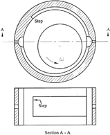
Plain cylindrical and other fixed pad bearings have been widely used in rotating machinery for many years. However, the instability of the rotor/bearing system may become a major problem in high-speed applications (Tonnesen and Flack (Citation17)). If a rotor with plain cylindrical or multilobe bearings experiences an instability problem, a conversion to the pressure dam bearing often provides a potential timely solution. Since the only modification is to machine a shrouded Rayleigh step on the top pad, it is also more cost effective than the alternative tilting pad bearings. As shown in , this design has a step or dam cut in the upper pad, which generates a downward hydrodynamic force during operation. This added load helps to keep the journal's operating eccentricity high, and therefore increases the effective load and the instability onset speed (Nicholas (Citation10); Nicholas and Allaire (Citation11); Nicholas, et al. (Citation12), (Citation13)). Sometimes, a circumferential relief groove is also cut on the lower pad to further increase the journal eccentricity and rotor stability.
The characteristics of pressure dam bearings have been investigated in many previous studies. Some early theoretical work can be found in Hamrock and Anderson (Citation3) and Rayleigh (Citation14), and (Wilcock and Booser (Citation18)). In Allaire, et al. (Citation1) and Nicholas (Citation10), the step inertia effects were found negligible while the turbulence in the pocket was found to be significant. From Nicholas (Citation10), Nicholas and Allaire (Citation11), and Nicholas, et al. (Citation12), it was discovered that the most important geometrical parameters for stability were the step height ratio and the angular location of the dam. If the step height and the bearing radial clearance are h s and c respectively, the step height ratio is defined as K′ = (h s +c)/c. The optimum value for the best rotor/bearing stability was theoretically determined to be approximately 3.0 < K′ < 6.0 (Citation11). But a larger K′ is preferable in practice since the step may wear down or collect debris during operation. The optimum dam location was determined to be from 125° to 160°, assuming solely downward applied load vector. The stability advantage of the pressure dam bearing and its optimum geometry were verified by many research experiments (Flack, et al. (Citation2)); (Lanes, et al. (Citation4)); (Nicholas, et al. (Citation13)); (Zuck and Flack (Citation19)). Mehta (Citation6), Mehta, et al. (Citation7), (Citation8), and Mehta and Singh (Citation9) also reported the dynamic analysis of noncylindrical pressure dam bearings which were found to be more stable than conventional pressure dam bearings and other fixed geometry bearings.
Despite the progress in previous studies and the continuing interest in pressure dam applications, only isoviscous pressure dam bearing analyses have been reported in the literature. Since stability problems usually occur at relatively high rotational speeds, it is certainly desirable to include the thermal effects in the theoretical modeling. This article presents a computationally efficient adiabatic thermohydrodynamic (THD) algorithm for pressure dam bearing analysis. The algorithm is then applied to the bearings experimentally investigated in Zuck and Flack (Citation19). The results indicate that the lubricant temperature rise has significant influence on the bearing performance and the inclusion of thermal effects directionally improves the stability prediction compared to an isoviscous analysis.
THEORETICAL MODELS
The pad pressure distribution can be solved from the generalized Reynolds equation, which takes into account both turbulence and the cross film viscosity variation (Safar and Szeri (Citation15)).
where the effective viscosity is defined as μ e = μ (1 + δϵ m /ν). Clearly, the effective viscosity is a linear combination of the lubricant dynamic viscosity (μ) and the eddy viscosity (ϵ m ) due to turbulence. The eddy viscosity can be calculated from the Reichardt's formula (Suganami and Szeri (Citation16)).
Following Suganami and Szeri (Citation16), the level of turbulence is determined by two critical Reynolds numbers.
If the maximum local Re hmax is smaller than the lower critical Reynolds number Re L , the flow is laminar and the scaling factor δ is zero, thus eliminating the eddy viscosity term. If Re hmax is greater than the upper critical Reynolds number Re H , the flow is fully developed turbulence and δ has the full scale of unity. If Re hmax is between Re L and Re H , the bearing flow is transitional and δ is scaled between zero and one. Since a stepped pad has very difference clearances outside the pocket compared to inside the pocket, δ is calculated separately in those regions. While the pocket region typically has strong turbulence, laminar flow may still prevail outside the pocket where the clearance is usually much smaller. On the edges of a pad, the pressure is specified at the ambient pressure. In the cavitation zone, the pressure is the cavitation pressure P cav. At the onset of cavitation, the Reynolds boundary condition is applied (∂ p/∂ x = 0,p = P cav).
An adiabatic energy equation is employed to calculate the film temperature distribution. The adiabatic equation assumes a constant radial temperature profile and no heat transfer to the adjacent solid surfaces. If all parameters are averaged in the radial direction, the equation can be solved in the circumferential and axial directions (x and z).
Any turbulence effects are included in the effective viscosity. The velocity components and their derivatives are obtained after the solution of the Reynolds equation. Although EquationEq. [4] has second-order conduction terms, the first order circumferential convection term is dominant in magnitude, which is typical in fluid film bearings. Consequently, the boundary condition at the pad leading edge is of the most importance. Based on energy conservation in the oil groove, the pad inlet temperature can be calculated as the mixture of both hot carryover and cool inlet oil using the equation
The film temperature at the pad leading edge is specified at this mixing temperature within the groove. In the cavitation region, the fluid film is in the form of streamlets and the mass flow must be conserved. As a result, the lubricant film is assumed to have reduced effective axial length. Utilizing these theoretical models, a comprehensive thermohydrodynamic algorithm is developed to analyze the pressure dam bearings. The governing differential equations are solved by the finite element method.
RESULTS AND DISCUSSIONS
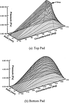
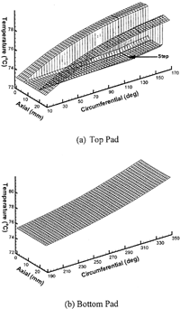
The current THD analysis is applied to model the bearings in Zuck and Flack (Citation19). The bearing geometries and operating conditions are summarized in . The external load is constant while the shaft speed varies from 2000 rpm to 8000 rpm. shows the predicted pressure distributions in bearing 1 at 6000 rpm. In the circumferential direction of the top pad, the maximum pressure is always located at the step and the profile is fairly linear inside the pocket as shown in . In the axial direction, the hydrodynamic pressure does not have much variation inside the pocket, but it drops quickly to the ambient pressure over the axial dam regions. Similar characteristics of the pressure distribution can also be found in Mehta (Citation6) and Nicholas (Citation10). The pressure profile is smooth on the bottom pad as shown in . The maximum pressure point is highly dependent upon the specific journal operating position. The temperature distributions for the same case are plotted in . The temperature distribution on the stepped top pad is quite different from that on a smooth pad. As shown in , it can be divided into three distinct regions. In the two axial dam regions, where the clearance is small and continuous, the temperature increases smoothly from the leading edge to the trailing edge. This trend is similar to that of a smooth bearing pad However, in the pocket region, the temperature rise is much lower due to the relatively weak viscous shearing. The increase is only about 1°C from the leading edge to the step. In the region after the step, where the clearance is significantly reduced, the temperature in the central area is still much lower that that in the axial dam regions although its gradient increases. On the bottom pad, the temperature increases smoothly from the leading edge to the trailing edge, showing negligible axial variation in .
TABLE 1 Bearing Specifications and Test Conditions, Ref. (Citation19)
It is known that the radial heat variation may be important for accurate thermal modeling. Besides the lubricant temperature, the pad temperature is also a major concern in practice. Therefore, it is often desirable to include the radial heat conduction in modern bearing analysis. However, this extension directly leads to the full three-dimensional energy equation, which considerably increases the amount of computation. For a more computationally efficient algorithm, the axial temperature is usually assumed constant and the temperature is solved only in the circumferential and radial directions (x and y). This simplification is sufficiently accurate for most smooth pad bearings, as shown in . However, for a pocketed pad, indicates that the temperature distribution has substantial axial variations and the simplification above is invalid. To include the radial heat conduction and improve the current adiabatic analysis, the computationally intensive three-dimensional energy equation must be solved.
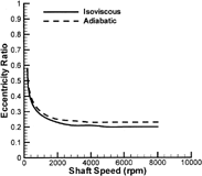
To demonstrate the thermal effects, both isoviscous and adiabatic analyses were conducted in the current study. shows the journal eccentricity ratio as a function of the shaft rotational speed. In the current isoviscous analysis, the lubricant viscosity was assumed to be at the supply temperature (31.5 cP at 63°C). In the adiabatic analysis, the operating lubricant viscosity is lowered in accordance with the calculated temperature rise. The method of direct calculation is more accurate and convenient than the method of effective viscosity, which depends on industrial experience. Since the adiabatic analysis simulates the bearing with a less viscous lubricant, the predicted eccentricity ratio is consequently higher. In , both the isoviscous and adiabatic curves are fairly flat, confirming the effectiveness of the pressure dam. As the shaft speed increases, the hydrodynamic force produced by the upper pad also builds up, which keeps the operating eccentricity almost invariant.
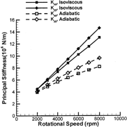
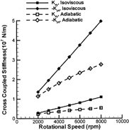
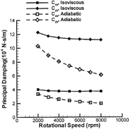
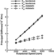
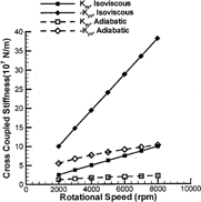
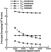
The dynamic coefficients of the bearings are presented from , where some consistent trends are observed. First, the adiabatic analysis always predicts lower stiffness and damping coefficients. This is the direct result of the reduced effective viscosity in the adiabatic analysis. Because the thermal effects are more significant at high speeds, the two types of analysis exhibit growing differences with increasing shaft speed. Second, increasing the shaft speed leads to a stiffer bearing as shown by the isoviscous curves. However, in the adiabatic analysis, this stiffening trend is greatly alleviated by the decreasing effective viscosity. In the adiabatic analysis, the decreasing effective viscosity also reduces bearing damping, which accelerates the decline of the damping curves. Although the thermal effects are clearly significant, with reductions in both cross-coupled stiffness and principal damping, it is difficult to assess the direct influence of temperature on the stability of a rigid or flexible rotor from these plots.
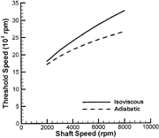
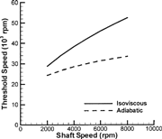
A direct method to examine the stability is to calculate the rigid rotor stability threshold speeds (Lund and Saibel (Citation5)). This method excludes the flexible dynamics of the rotor and is solely dependent on the bearing properties. As shown in , the adiabatic predictions give relatively lower instability onset speeds for these particular bearings. Thus, the inclusion of the thermal effects seems necessary for accurate instability predictions.
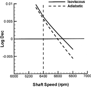
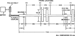
Zuck and Flack (Citation19) conducted experiments to measure the instability onset speed of a flexible rotor supported by two pressure dam bearings. The rotor drawing is shown in . The dynamic coefficients of the bearings are given in . The bearing on the overhung disk side (bearing 2) is noticeably stiffer because it has a smaller clearance and carries a higher load. In Zuck and Flack (Citation19), the rotor started to show shaft whip at 6400 rpm. Additionally, the frequency of the subsynchronous vibration was approximately 3000 cpm, which was near the rotor's first critical speed. In the theoretical rotor-dynamic analysis, the instability onset speed is determined by inspecting the logarithmic decrement of the first forward mode. A negative logarithmic decrement indicates an unstable rotor. As shown in , the predicted logarithmic decrement of the first forward mode becomes negative at about 6600 rpm in the adiabatic analysis, which leads to an error of 3.1%. The first damped natural frequency is calculated at 3086 cpm, which is in excellent agreement with the experimental data. The stability threshold occurs at 6700 rpm using the current isoviscous analysis (4.7% error). In Zuck and Flack (Citation19), the instability onset speed was predicted at 5800 rpm (−9.4% error), which is lower than the current isoviscous prediction. Different hydrodynamic algorithms and inputs could give different bearing coefficients, which would produce different stability predictions Different rotor models and rotor stability algorithms could also lead to different stability results. Since the theoretical details were not presented in Zuck and Flack (Citation19), the exact causes cannot be clearly identified. Nevertheless, comparison of these results indicates that current adiabatic analysis directionally improves the correlation between the theoretical predictions and the experimental results.
FIG. 13 Overhung rotor drawing; see Zuck and Flack (Citation19).
CONCLUSIONS
This study presents a full adiabatic THD algorithm for pressure dam bearing analysis. The numerical results show that the lubricant temperature variation has substantial influence on the bearing performance. Compared to the current isoviscous analysis, the inclusion of the thermal effects tends to increase the journal operating eccentricity, decrease the stiffness and damping coefficients, and decrease the rigid rotor stability threshold speeds. As an example, the adiabatic analysis also improves the stability prediction for the rotor/bearing system in reference (Citation19). While the pressure distribution is similar to those obtained in previous studies, the temperature distribution shows three distinct regions, implying that the two-dimensional equation that assumes constant axial temperature profile cannot be applied to a pressure dam pad. Instead, the full three-dimensional energy equation must be employed to model the radial heat conduction and the pad temperature.
Acknowledgments
Presented at the STLE/ASME Tribology Conference in Ponte Vedra Beach, Florida October 27-29, 2003 Final manuscript approved June 16, 2003 Review led by Henry Sneck
REFERENCES
- Allaire , P. , Nicholas , J. and Barrett , L. 1978 . “Analysis of Step Journal Bearings-Infinite Length, Inertia Effects” ASLE Preprint No. 78-AM-38–1
- Flack , R. , Leader , M. and Gunter , E. 1980 . “An Experimental Investigation on the Response of a Flexible Rotor Mounted in Pressure Dam Bearings” . ASME Jour. of Mech. Design , 102 : pp 842 – 850 .
- Hamrock , B. and Anderson , W. 1969 . “Rayleigh Step Journal Bearing, Part II—Incompressible Fluid” . Jour. of Lubr. Tech. , 90 : pp 641 – 650 .
- Lanes , R. , Flack , F. and Lewis , D. 1983 . “Experiments on the Stability and Response of a Flexible Rotor in Three Types of Journal Bearings” . ASLE Trans. , 25 : pp 289 – 298 .
- Lund , J and Saibel , E. 1967 . “Oil Whip Whirl Orbits of a Rotor in Sleeve Bearings” . Jour. of Engineering for Industry , 89 : pp 813 – 823 .
- Mehta , N. 1993 . “Static and Dynamic Characteristics of Orthogonally Displaced Pressure Dam Bearings” . Trib. Trans. , 36 : pp 201 – 206 .
- Mehta , N. , Singh , A. and Gupta , B. 1986 . “Stability of Finite Elliptical Pressure Dam Bearings with Rotor Flexibility Effects” . ASLE Trans. , 29 : pp 548 – 557 .
- Mehta , N. , Singh , A. and Gupta , B. 1986 . “Dynamic Analysis of Finite Half-Elliptical Pressure Dam Bearings with Rotor Flexibility Effects” . ASLE Trans. , 29 : pp 61 – 66 .
- Mehta , N. and Singh , A. 1986 . “Stability Analysis of Finite Offset-Halves Pressure Dam Bearings” . Jour. of Trib. , 108 : pp 270 – 274 .
- Nicholas , J. 1977 . “A Finite Element Dynamic Analysis of Pressure Dam and Tilting Pad Bearings,” , University of Virginia . Ph.D. Dissertation
- Nicholas , J. and Allaire , P. 1979 . “Analysis of Step Journal Bearings—Finite Length Stability” . ASLE Trans. , 22 : pp 197 – 207 .
- Nicholas , J. , Allaire , P. and Lewis , D. 1980 . “Stiffness and Damping Coefficients for Finite Length Step Journal Bearings” . ASLE Trans. , 23 : pp 353 – 362 .
- Nicholas , J. , Barrett , L. and Leader , M. 1980 . “Experimental-Theoretical Comparison of Instability Onset Speeds for a Three Mass Rotor Supported by Step Journal Bearings” . ASME Jour. of Mech. Design , 102 : pp 344351
- Rayleigh , L. 1918 . “Notes on the Theory of Lubrication” . Phil. Mag. , 35 : pp 1 – 12 .
- Safar , Z. and Szeri , A. 1974 . “Thermohydrodynamic Lubrication in Laminar and Turbulent Regimes” . Jour. of Lubr. Tech. , 96 : pp 48 – 56 .
- Suganami , T. and Szeri , A. 1979 . “A Thermohydrodynamic Analysis of Journal Bearings” . Jour. of Lubr. Tech. , 101 : pp 21 – 27 .
- Tonnesen , J. and Lund , J. 1978 . “Some Experiments on Instability of Rotors Supported in Fluid Film Bearings” . ASME Jour. Mech. Design , 100 : pp 147 – 155 .
- Wilcock , D. and Booser , E. 1957 . Bearing Design and Application , New York : McGraw-Hill .
- Zuck , C. and Flack , R. 1986 . “Experiments on the Stability of an Overhung Rotor in Pressure-Dam and Multilobe Bearings” . ASLE Trans. , 30 : pp 225 – 232 .
