Abstract
The compression force of refrigerant gas, the viscous and inertial force of the piston, and the centrifugal force of balancer weight induce rotating whirl of the crankshaft in a small reciprocating compressor. It is necessary to develop an analytical model for the accurate prediction of dynamic behavior of the compressor mechanism having coupled characteristics between the piston and crankshaft. The reciprocating compression mechanism is dynamically modeled by considering the viscous frictional force of a piston and the variation in the contact length of the piston-cylinder system, and then numerical analysis is performed for the coupled dynamic behavior of the piston and crankshaft. For the accurate predictions of the dynamic behavior and characteristics of lubrication of the crankshaft-journal bearing system, a finite bearing model is adopted. In addition, the dynamic trajectory and characteristics of lubrication of the crankshaft such as power consumption and oil leakage are compared between the finite bearing model and the short bearing approximation. The influences of the variation in the radial clearance of the journal bearings, lubricant viscosity, and mass and mass moment of inertia of the piston and connecting rod on the dynamic behavior and characteristics of lubrication such as power consumption and oil leakage are investigated.
INTRODUCTION
In a small reciprocating compressor employed in refrigeration appliances, the slider-crank mechanism, which consists of a cylinder block, a piston, a connecting rod, and a crankshaft supported on journal bearings is widely used. Rotating whirl of the crankshaft occurs from the loads such as compression force of the refrigerant gas, the viscous frictional force of the piston, the inertial force of the piston and the connecting rod, and the centrifugal force produced by the balancer weight of crankshaft. Therefore, it is necessary to develop an analytical model for the accurate prediction of the dynamic behavior of compressor mechanisms having coupled characteristics between the piston and crankshaft.
| C | = |
radial clearance of the journal bearings |
| C p | = |
radial clearance between the piston and cylinder wall |
| e b , e t | = |
eccentricities of bottom and top planes of piston, |
| X 1, Y 1, X 2, Y 2 | = |
X and Y directional eccentricities of crankshaft on mid-planes of main bearing and sub-bearing, |
| F bxi , F byi | = |
hydrodynamic forces in X and Y directions of journal bearings, |
| F f | = |
viscous friction force between piston and cylinder, |
| F fi | = |
viscous friction force of journal bearings, |
| h | = |
oil film thickness for an eccentricity and tilted piston |
| h i | = |
radial clearance between crankshaft and bearings (i = 1 for main bearing and i = 2 for sub-bearing) |
| Ip | = |
piston moment of inertia about piston-pin, |
| I x , I y , I z | = |
moment of inertia of crankshaft and motor rotor about its center of mass in X, Y, Z directions, |
| l p | = |
contacting length between the piston and cylinder wall |
| L f | = |
axial distance between center of crankshaft gravity and crank-pin center |
| M bxi , M byi | = |
hydrodynamic moments of journal bearings in X and Y directions about its center of mass, |
| M x , M y | = |
load moments of crankshaft in X and Y directions, |
| p | = |
oil film pressure between piston and cylinder, |
| p i | = |
oil film pressure of journal bearings, |
| Q x | = |
cycle-averaged volumetric oil leakage of piston, |
| Q zi | = |
cycle-averaged volumetric oil leakage of journal bearings, |
| R | = |
radius of crankshaft on journal bearings |
| R p | = |
radius of the piston |
| S x , S y | = |
forces upon crankshaft in X and Y directions, |
| T x , T y | = |
forces upon piston in X and Y directions, |
| V p | = |
piston axial velocity |
| W avg | = |
cycle-averaged power consumption by viscous friction of piston, |
| W i | = |
instantaneous power consumption by viscous friction of journal bearings, |
| X 0, Y 0 | = |
displacements of crankshaft in X and Y directions on axial center of mass, |
| θ, | = |
nondimensional coordinates of circumferential and axial direction of piston, |
| θ
i
, | = |
nondimensional coordinates of journal bearings, |
| α,β | = |
rotating angles of crankshaft around X and Y axes, |
| γ | = |
rotating angle of piston around z axis, |
| λ | = |
viscosity of the lubrication oil |
| ω | = |
crankshaft angular velocity |
Many methods for solving the crankshaft orbits of the dynamically loaded journal bearings are available: the short bearing assumption (Kirk and Gunter (Citation1); Hattori and Kawashima (Citation2); Hamrock (Citation3)), the mobility method that utilizes the stored bearing characteristics (Booker (Citation4)), and FEM (Goenka (Citation5)). In the short bearing theory, assuming that resistances from the axial endwise flow of the bearings are disregarded, circumferential pressure flows are neglected as compared to the axial pressure flows. As a result, the short bearing theory gives excessive load-carrying capacities for the finite-width journal bearings at diameter-to-width ratios less than 2. Also, the solution of the Reynolds equation for the dynamically loaded journal bearings can be numerically determined using a finite volume method and Elrod cavitation algorithm (Elrod (Citation6); Brewe (Citation7); Kim and Han (Citation8)). But in this analysis, in general it is difficult to know the value of the bulk modulus (compressibility factor) of the lubricant easily and exactly. Dynamic analysis of the secondary motion of the piston and characteristics of fluid film lubrication are required to get a viscous friction force of a piston. Therefore, a proper dynamic modeling and numerical methods must be developed for the analysis. In the previous studies, friction force between piston and cylinder wall was obtained by assuming the Coulomb friction coefficient μ = 0.03 (Citation9), μ = 0.35 (Dulfour, et al. (Citation10)). It is difficult to assume the range of this coefficient value without an experimental verification. Early studies on the piston slap model were attempted to solve the contact problem for the reciprocating piston in automotive engines by calculating the piston impact forces. However, close approximations of the measurements were not achieved because of the lack of proper consideration of hydrodynamic lubrication. Li, et al. (Citation11) performed a calculation for the trajectory of piston and friction characteristics including a hydrodynamic lubrication model of a piston. Zu, et al. (Citation12) presented a numerical analysis on the dynamics of a piston-cylinder assembly by considering the geometry of the piston and cylinder surface. Gommed, et al. (Citation13) proposed a mathematical model for analyzing the dynamics of gas lubricated ringless pistons. Also, there is a study on impact and vibration of an engine block produced by piston slap (Nakada, et al. (Citation14)). In the case of reciprocating compressors, there are a couple of studies on the secondary dynamics of ring-less piston (Prata, et al. (Citation15); Kim (Citation16)).
Since compressor manufacturing is characterized by mass production, the effects of enhancing performance and reducing power consumption is very high. And, in order to reduce power consumption and enhance easy assembly of the compression mechanism, the length of the cylinder bore is in the trend of being shortened. Since diameter-to-width ratios of the main bearing and sub-bearing of the analysis model of the compressor are 0.82, and 0.6, respectively, a finite bearing model should be applied for accurate calculation. In this article, the reciprocating compression mechanism is dynamically modeled by considering the viscous frictional force of a piston and the variation in the contact length of the piston-cylinder system, and then numerical analysis is performed for the coupled dynamic behavior of the piston and crankshaft. For the accurate predictions of the dynamic behavior and characteristics of lubrication of the crankshaft-journal bearing system, a finite bearing model is adopted. The dynamic trajectory and characteristics of lubrication of the crankshaft such as power consumption and oil leakage are compared between the finite bearing model and the short bearing approximation (Kirk and Gunter (Citation1); Hattori and Kawashima (Citation2); Hamrock (Citation3)). The influences of the variation in the radial clearance of the journal bearings, lubricant viscosity, and mass and mass moment of inertia of the piston and connecting rod on the dynamic behavior and characteristics of lubrication such as power consumption and oil leakage are investigated.
DYNAMIC FORMULATION
Piston Secondary Dynamics
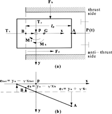
The loads T x , T y acting on the piston and S x , S y acting on the crankshaft are derived from the kinematics of the connecting rod system, the equation of motion of the reciprocating piston, and the equations of motion for translation and rotation of the connecting rod. A free body diagram of the piston within the cylinder bore is shown in . With the aid of this figure, the nondimensional radial equation of motion of the piston can be written as,
Crankshaft Dynamics
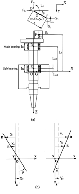
By considering the unbalanced load produced by the eccentric mass of the crankshaft as shown in , and gyro moments of the motor rotor, dimensionless equations of motion of translation and rotation of rigid crankshaft are derived,
HYDRODYNAMIC ANALYSIS
Fluid Film Between Piston and Cylinder Wall
The Reynolds equation for the incompressible and laminar flow can be written in nondimensional form as
Assuming the direction of viscous frictional force acting on the piston to be opposite to the axial direction, the friction force and friction moment can be given by
Finite Bearing Model
To solve the fluid film lubrication problem between the crankshaft and the journal bearings, the nondimensional Reynolds equation can be written as,
NUMERICAL PROCEDURE AND RESULTS
Numerical Procedure
It is assumed that the initial values of ϵ
b
(t), ϵ
t
(t),
b
(t),
t
(t), ϵ
ix
(t), ϵ
iy
(t),
ix
(t), and
iy
(t) (i = 1,2), and viscous friction force F
f
are zero. The constraint forces T
x
, T
y
and S
x
, S
y
of the compression mechanism are calculated by the Newton-Raphson method and hydrodynamic forces F
f
, F
h
and moments M
f
, M
h
are calculated by the SOR scheme. The adjustment of
b
(t+Δt) and
t
(t+Δt) can be done with a quasi-Newton method, and
, and
can be computed. For the computational level j + 1,
b
(t + Δt),
t
(t + Δt), ϵ
j +1
b
(t) and
(t) are calculated using the previous values at level j. During the iterative process, if the convergence criterion
and
are satisfied, the trajectories of the crankshaft are obtained using a quasi-Newton procedure to search for the
ix
(t+Δt),
iy
(t+Δt) values that would satisfy the nonlinear EquationEqs. (15)–(18) and then,
, and
are calculated. For the computational level
and
are calculated using the previous values at level m, satisfying the system of nonlinear equation of the crankshaft. If the convergence criteria
are satisfied, then proceed to the next time step utilizing the solution ϵ
b
(t+Δt), ϵ
t
(t+Δt),
b
(t+Δt),
t
(t+Δt), ϵ
ix
(t+Δt),
ix
(t+Δt), ϵ
iy
(t+Δt), and
iy
(t+Δt). If it is not satisfied, the previous procedure can be repeated.
RESULTS AND DISCUSSION
Design parameters of the reciprocating compressor and baseline values used in the simulation are given in . The compressor is considered to be operating at the speed of 3570 rpm and on the suction pressure p
s
= 0.132 MPa and discharge pressure p
d
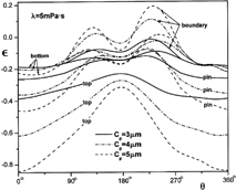
= 1.352 MPa. Under the condition of oil viscosity 5 mPa·s and the clearance between piston and cylinder wall 4 μm, the numerical results for the radial direction orbits of the piston centers locating at the piston top, piston-pin, piston boundary, and piston bottom, are shown in . This figure shows the periodic solutions for the piston trajectories converging from the initial conditions, ϵ
b
(t) = ϵ
t
(t) =
b
(t) =
t
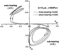
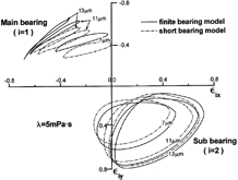
(t) = 0. From this result, it can be seen that the trajectories of boundary and bottom location are branched off from the same line in the region of the crank angle 79.86°∼ 280.15°. This is because of the protrusion of the piston bottom part from the inside of the cylinder bore induced by the shortened length of the cylinder. The trajectory of the piston top center closes to the thrust side of the cylinder wall, but the pistonbottom center lies on the centerline of the cylinder. The number of iterations for satisfactory convergence is within 20–30 rotating cycles, and the calculation using the Newton-Raphson scheme is converged within 3–4 cycles. Dynamic trajectories of the crankshaft are compared between a finite bearing model and a short bearing approximation in . When the diameter-to-width ratio is above 2 the short bearing approximation is reasonable, but when the ratio is below 2 it is known that high oil film pressure is computed. In the case of the short bearing approximation, circumferential pressure flow is disregarded and higher load-carrying capacity for the finite bearing is calculated. Therefore, the crankshaft trajectory of the short bearing model is smaller than that of the finite bearing model. Also, a converged periodic solution for the crankshaft trajectory is required within 3–4 cycles.
FIG. 3 The radial direction orbits at 4 locations of the piston showing the converged periodic solution.
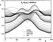
TABLE 1 Design Parameters of the Reciprocating Compressor and Baseline Values Used in the Simulation
At a lubricant viscosity of 5 mPa.s, the variation of dynamic behaviors of the piston and crankshaft are obtained with different radial clearances between the piston skirt surface and the cylinder wall of 3, 4, and 5 μm. It can be shown that the radial trajectories of the piston are stabilized with a decrease in clearance as shown in . This is because of the increase in damping effect of the oil film with a decrease of clearance. However, in the case of the crankshaft, this variation of piston clearance does not affect the journal orbits. When radial clearance of the piston becomes enlarged, the average power consumption of the piston per cycle decreases nonlinearly, but the average oil leakage per cycle increases as shown in . The effects of the oil viscosity on the radial clearance between the piston skirt and the cylinder wall are shown in . The average power consumption of the piston per cycle increases almost linearly with the oil viscosity, while the average oil leakage per cycle varies in inverse proportion to the lubricant viscosity. The trajectory of the crankshaft and lubrication characteristics are compared between a finite bearing model and a short bearing model under the condition of radial clearances of the bearing of 7, 11, and 13 μm. It is shown that the trajectory of the crankshaft is stabilized due to an increase of damping effect of the oil film with a decrease of clearance of the journal bearings in . In the main and sub-bearings, the general tendency of the lubrication characteristics is that the average power consumption per cycle decreases but the average oil leakage increases, as shown in . From the numerical results of the shaft trajectory in , the difference of trajectory sizes of the sub-bearing part is not substantial compared with the main bearing part. It is also found that this fact is reflected in lubrication characteristics as shown in .
FIG. 6 Cycle-averaged power consumption and oil leakage of the piston as a function of radial clearance.
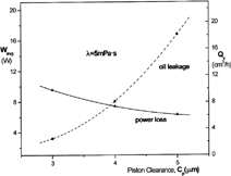
FIG. 7 Cycle-averaged power consumption and oil leakage of the piston as a function of lubricant viscosity.
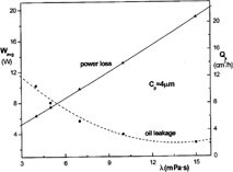
FIG. 9 Cycle averaged power consumptions and oil leakages of the crankshaft as a function of clearance at main bearing.
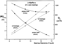
FIG. 10 Cycle averaged power consumptions and oil leakages of the crankshaft as a function of clearance at sub bearing.
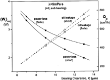
The average power consumption for the finite bearing model is higher than that of the short bearing model, while the average oil leakage per cycle of the short bearing theory is larger than that of a finite bearing model. Since the trajectories of the crankshaft using the finite bearing model are larger than those of a short bearing model, it can be understood that power consumption for the finite bearing model is higher. However, short bearing approximation theory is based on the fact that the axial pressure gradient is dominant compared with the circumferential gradient; therefore, axial oil leakage of a short bearing model is greater than that of a finite bearing model. Also, comparing with the aforementioned power consumption and oil leakage of the piston, the power consumptions of the journal bearings have similar values, while oil leakages of the journal bearings are substantially different from the values of the piston. This is because, in the case of the piston, the amount of oil leakage is determined by the difference between the suction and discharge of oil during the reciprocating behavior of the piston. In the case of the journal bearings, oil is continuously leaking out and the clearance of the bearings is much larger than that of piston as well.
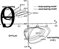
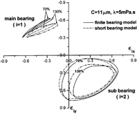
Under a radial clearance of 11 μm in the journal bearings, generally the trajectory of the crankshaft is stabilized with an increase of lubricant viscosity, as shown in . From , the average power consumption increases with the oil viscosity, but the average oil leakage per cycle decreases with the oil viscosity. The trajectory of the crankshaft is shown in under the condition of varying mass and mass moment of inertia of −30%, 30% of the value presented in . The trajectory of the piston is stabilized with a decrease of mass and mass moment of inertia of the piston and connecting rod, but the trajectory of the crankshaft is destabilized. This is because the radial load acting on the piston decreases with the decrease of inertial effect of the piston and connecting rod, and the trajectory of the piston in the radial direction is stabilized due to a reduction of exciting force on the piston. However, the trajectory of the crankshaft is destabilized with a decrease of mass and mass moment of inertia of the piston and connecting rod, since these inertial forces influence the loads exerted on the crankshaft. Since the dynamic trajectory of the crankshaft is not largely affected by the increase of mass and mass moment of inertia of piston and connecting rod as shown in , it is found that average power consumption per cycle and average oil leakage per cycle as shown in are not largely changed either. In the same manner as before, the average power consumption using a finite bearing and the average oil leakage using a short bearing model are calculated as a higher value than if using a short, finite bearing model in the respective case.
TABLE 2 Comparison of the Friction Losses and Oil Leakages with Respect to the Bearing Analysis Model
CONCLUSION
The reciprocating compression mechanism is dynamically modeled by considering the viscous frictional force of a piston and the variation in contact length of the piston-cylinder system. Dynamic behavior and characteristics of lubrication of the crankshaft supported by two journal bearings are compared between a theoretically accurate, finite bearing model and a short bearing assumption.
In the short bearing theory, since circumferential pressure is neglected and higher oil pressure is computed, the trajectories of the crankshaft using a finite bearing model are larger than that of a short bearing model. So, power consumption of a finite bearing model is greater than that of a short bearing model, while axial oil leakage of a finite bearing model is lower than that of a short bearing model. When increasing lubricant viscosity, the trajectory of the crankshaft is stabilized but power consumption is increased and oil leakage is decreased. Concerning the effect of variation on the radial clearance of journal bearings, the trajectory of the crankshaft is destabilized when the increase of the factor and the oil leakage is increased, but power consumption is reduced. As radial clearance of the journal bearings is decreased, the differences of power consumption and oil leakage between finite and short bearing model decrease as well.
A theoretically accurate finite bearing model is adopted to simulate coupled dynamic characteristics between the piston components in which the viscous frictional force is considered along with the crankshaft-journal bearing system. Also, the program developed can be used as a helpful tool in assessing the influence of design parameters on the stability and lubrication characteristics of the reciprocating compressor mechanism.
ACKNOWLEDGMENT
This work was supported by a grant (No. R01-2001-00383) from the Korea Science and Engineering Foundation.
Presented at the STLE/ASME Tribology Conference in Ponte Vedra Beach, Florida October 27-29, 2003 Final manuscript approved May 10, 2003 Review led by Bill Marscher
REFERENCES
- Kirk , R. G. and Gunter , E. J. 1975 . “Short Bearing Analysis Applied to Rotor Dynamics, Part 1: Theory” . Jour. of Lubr. Tech. , : pp 319 – 329 . April
- Hattori , H. and Kawashima , N. 1991 . “Dynamic Analysis of a Rotor-Journal Bearing System with Large Dynamic Loads” . JSME Int. Jour. , 34 ( 4 ) : pp 503 – 511 .
- Hamrock , B. J. 1994 . Fundamentals of Fluid Film Lubrication , pp 230 – 235 . McGraw-Hill .
- Booker , J. F. 1971 . “Dynamically Loaded Journal Bearings: Numerical Application of the Mobility Method” . ASME Jour. of Lubr. Tech. , : pp 168 – 176 . January
- Goenka , P. K. 1984 . “Dynamically Loaded Journal Bearings: Finite Element Method Analysis” . ASME Jour. of Trib. , 106 : pp 429 – 439 .
- Elrod , H. G. 1981 . “A Cavitation Algorithm” . ASME Jour. of Lubr. Tech. , 103 : pp 350 – 354 .
- Brewe , D. E. 1986 . “Theoretical Modeling of the Vapor Cavitation in Dynamically Loaded Journal Bearings.” . ASME Jour. of Trib. , 108 : pp 628 – 638 .
- Kim , T. J. and Han , D. C. 1998 . “Dynamic Behavior Analysis of Scroll Compressor Crankshaft Considering a Cavitation Phenomenon in Dynamically Loaded Journal Bearings” . Trans. of KSME, A , 22 ( 8 ) : pp 13751389
- Ishii , N. , Imaichi , K. , Kagoroku , N. and Imasu , K. 1975 . “Vibration of a Small Reciprocating Compressor,” ASME Paper 75-DET-44
- Dufour , R. , Hagopian , J. and Der Lalanne , M. 1995 . “Transient and Steady State Dynamic Behavior of Single Cylinder Compressors: Prediction and Experiments” . Jour. of Sound and Vibration , 181 ( 1 ) : pp 23 – 41 .
- Li , D. F. , Rohde , S. M. and Ezzat , H. A. 1983 . “An Automotive Piston Lubrication Model” . ASLE Trans. , 26 ( 2 ) : pp 151 – 160 .
- Zhu , D. , Cheng , H. S. , Arai , T. and Hamai , K. 1992 . “A Numerical Analysis for Piston Skirts in Mixed Lubrication Part 1: Basic Modeling” . Jour. of Trib. , 114 : pp 553 – 562 .
- Gommed , K. and Etsion , I. 1993 . “Dynamic Analysis of Gas Lubricated Reciprocating Ring-less Piston-Basic Modeling” . Trans. ASME, Jour. of Trib. , 115 : pp 207 – 213 .
- Nakada , T. , Yamamoto , A. and Abe , T. 1997 . “A Numerical Approach for Piston Secondary Motion Analysis and its Application to the Piston Related Noise,” SAE Paper No. 972043
- Prata , A. T. , Fernando Julio , R. S. and Fagotti , F. 2000 . “Dynamic Analysis of Piston Secondary Motion for Small Reciprocating Compressors” . Trans. ASME, Jour. of Trib. , 122 : pp 752 – 760 .
- Kim , T. J. 2003 . “Numerical Analysis of the Piston Secondary Dynamics in Reciprocating Compressors” . KSME Int. Jour. , 17 ( 3 ) : pp 350 – 356 .
