Abstract
Surfaces and subsurfaces of test specimens that failed in scuffing were examined. A scuffing criterion is developed stating that scuffing failure would occur when the maximum surface tangential traction is larger than the modified shear strength. A scuffing uncertainty factor is introduced to reflect the influence of factors that affect wear and scuffing and the inaccuracy in modeling.
INTRODUCTION
Scuffing is a detrimental failure of mechanical elements in relative sliding. A few scuffing criteria have been developed. The critical surface temperature criterion (Blok (Citation1); Cuotiongco and Chung (Citation2); Johnson, et al. (Citation3); Yang, et al. (Citation4)) relates scuffing to a critical temperature condition. The critical subsurface stress criterion (Somi Reddy, et al. (Citation5)) assumes that ductile rupture occurs when the shear stress at a critical depth under the surface exceeds the temperature-dependent shear strength of the material at this depth. The critical ratio of shear stress/hardness criterion (Biswas (Citation6)) relates scuffing to the gross plastic flow at a subsurface depth. The plastic index criterion (Greenwood and Williamson (Citation7); Hirst and Hollander (Citation8)) relates scuffing to surface roughening as a result of plastic flow and a critical amount of the plastic strain in the sliding track. The damage accumulation time criterion (Sheiretov (Citation9)) assumes that scuffing occurs when the damage accumulation time necessary for initiation and propagation of cracks is shorter than the time necessary for the damaged material to leave the critical zone of the fastest damage accumulation. The critical surface tangential traction criterion (He (Citation10); Yoon, et al. (Citation11)) assumes that scuffing occurs when the surface tangential traction exceeds the bulk shear strength. It is clear that any one of these hypotheses or criteria mentioned may be used only under certain conditions where a particular wear mechanism dominates the scuffing characteristics.
Scuffing behavior of an aluminum-silicon alloy for pistons in the piston-piston pin contact was studied experimentally in bench tests and the results were presented in part I of this study (Zhang, et al. (Citation12)). The experiments reveal that the scuffing resistance of the piston surface is reduced significantly by an increase in piston bore roughness. They also indicate that the addition of a circumferential groove results in a remarkable improvement in the piston scuffing resistance due to enhanced lubrication.
In the present work, the authors conducted an examination of the surfaces and subsurfaces of the specimens from the bench tests (Zhang, et al. (Citation12)) by means of an optical microscope and a scanning electron microscope (SEM) in order to study the scuffing mechanism of the piston-pin/bore contact in mixed lubrication. A simplified scuffing failure criterion is suggested for industrial applications.
BRIEF DESCRIPTION OF BENCH TESTS AND RESULTS
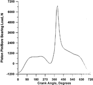
present views of the bench test apparatus and the piston-pin and piston specimens. The apparatus consists of a loading system, a drive system, a lubrication system, and an instrumentation system. This apparatus produces an oscillating surface velocity and a dynamic load. Simulations of the time-dependent dynamic load and the pin surface velocity over a complete engine cycle were accomplished mainly by a combination of camdriven mechanical springs and an oscillator. Details of the design have been reported in (Zhang, et al. (Citation12)). show the pin velocity variation corresponding to 1500 rpm of the drive-shaft speed and the bearing scuffing load measured prior to scuffing. show the oscillating surface velocity of the piston pin and the load acting on the piston-pin/bore bearing of a 4.6 L V8 2V four-stroke engine. The comparison of with reveals that the bench tests can simulate the kinetic and dynamic characteristics of the pin/bore bearings in an engine.
FIG. 1 General view of the bench rig.
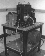
FIG. 2 Specimens.
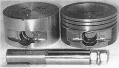
FIG. 3 Pin oscillating speed.
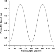
FIG. 4 Scuffing load.
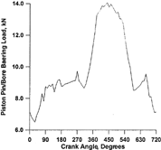
FIG. 5 The speed of a pin in an engine.
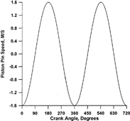
FIG. 6 The bearing load corresponding to the pin speed shown in .
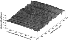
SAE-5W30 was used as the lubricant in the experiments. Production pistons and piston pins were used as samples. Piston pins were made of SAE 1016 steel hardened to Rockwell C: 62.2-71.8 with a root-mean-square (RMS) of roughness (σ, or Sigma) in the range of σ = 0.17-0.19 μm. Pistons were made of an aluminum silicon (Al-Si) alloy material. The roughness of unworn smooth pistons was 0.27-0.7 μm, which became 0.17-0.27 μm after running-in. shows an area of a typical surface of the piston bore after running-in.
FIG. 7 Measured surface area of a piston bore after running in.
MICROGRAPH ANALYSES OF THE PISTON SURFACES AND CROSS SECTIONS
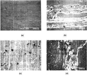
show the SEM micrographs of the piston bore surfaces in mild and severe wear, as well as a scuffing area, for the originally smooth and rough bore surfaces. The comparison between shows that, in the area where a mild wear occurred, the originally rough surface yielded more material flow and tearing, as well as more visible agglomerate debris. show that on the severely worn surfaces, there are a few shallow abrasive grooves. In the scuffing regimes, a more heavily deformed stratified patch is observed in than in . This observation suggests that roughness shortens the time for the transition from severe wear to scuffing. Obviously, roughness has a considerable effect on the wear process and scuffing.
FIG. 8 SEM micrograph of a piston bore surface after scuffing. (a) Smooth original surface (#XB-1 1), mild wear regime, (b) Smooth original surface (#XB-1 1), severe wear and scuffing regimes, (c) Rough original surface (#XER-4), mild wear regime and (d) Rough original surface (#XER-4), severe wear and scuffing regimes.
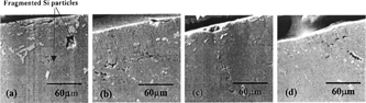
show the optical and SEM micrographs of the cross sections of the tested piston bores along the sliding direction. In the cross sections shown in , the brightest, darker, and darkest parts are the aluminum substrates, the primary silicon particles, and cracks, respectively. An examination of suggests that under the scuffed area, a transformed layer and a plastically deformed region may appear. Because of the cyclic loading and the oscillating motion of the pin, the piston bores underwent cyclic stress variations. As a result, the primary larger silicon particles were fragmented into smaller particles, as shown in , some of which become powder bands parallel to the surface as a result of the plastic flow in the sliding direction, as shown in . Voids and fatigue cracks might have nucleated at the interface between the fragmented silicon particles and the Al matrix and propagated along the intersection of the shear and powder bands. They are also observed in the stratified bands containing fragmented silicon particles and in the transfer layer as shown in and . Some surface-originated cracks stem from surface asperities as shown in . Cracks weaken the surface and substrate and release debris from the base alloy subsurface into the interface, as shown in , which were embedded again into the surface. It is obvious that the fatigue cracks strongly affect the wear and scuffing resistance of the material. In other words, the deterioration of the material strength by fatigue cracks contributes to the final scuffing.
FIG. 9 Optical micrograph of a cross section of a piston bore after scuffing, (a) Shear and powder bands, (b) Stratified bands containing extensively fragmented silicon particles and (c) Transfer layer.
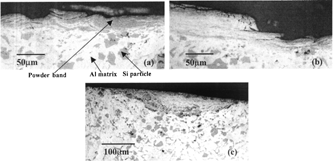
FIG. 10 SEM micrograph of cross sections of a piston bore after scuffing. (a) Fragmentation of primary silicon particles, (b) Crack nucleation and propagation along the Si particle-Al matrix interfaces and plastic flow, (c) Connection of cracks among neighbor fragmented Si particles and (d) Crack propagation into transfer layer.
SCUFFING MECHANISM
The loss of all of the successive protective layers of the sliding asperity finally results in scuffing. These protective films include the lubricant film generated by the microelastohydrodynamic action, an adsorbed or reactive surface film, and an oxide layer. Asperity sliding friction may also play an important role in the propagation of surface scuffing by producing frictional heating. Scuffing may initiate on a single asperity when its flash temperature exceeds a critical temperature. Microscuffing occurs if the single-asperity scuffing does not propagate much beyond its own initial contact area. When the thermal influence of the scuffed asperity raises its neighboring asperity temperatures to a critical value, those asperities would be affected and more asperities may scuff. The thermal influence of newly scuffed asperities also affects their neighboring asperities, and then scuffing may propagate to the entire contact area, resulting in scuffing failure, i.e., macro-scuffing.
On the other hand, the deterioration of the material strength by the flash temperature (Zhang, et al. (Citation12)) and the occurrences of material transfer, plastic deformation, fatigue cracks, and accumulated damage in the surface and substrate contribute to the final scuffing, although work hardening may increase the material strength (Lim and Asheby (Citation13)). Such material deterioration is especially important for the piston-pin/bore bearing because the contact is under the oscillating motion of the connecting rod, and the contacting materials are subjected to cyclic stresses. Scuffing would occur when the shear stresses in a certain substrate volume exceed the combined bulk shear strength there. Therefore, scuffing is governed by a group of mechanisms in the complex interaction among the phenomena mentioned above.
SCUFFING MODELING
The preceding discussion shows that shear stresses in a certain substrate volume and the combined bulk shear strength are two major parameters to predict scuffing failure. However, it is difficult to calculate the real stress in the worn Al-Si material, which is altered by wear and other deterioration effects mentioned before. A simplified scuffing model for industrial applications is needed and should be developed. This model involves the journal motion in the bearing clearance, the degree of contact between the journal and the bushing, the asperity contact pressure, the maximum flash temperature, and the surface tangential traction.
Journal Center Orbit, Asperity Contact, and Flash Temperature
A journal center orbit describes the journal motion in the bearing clearance volume. It can be used to determine the degree of contact between the journal and the bushing. A number of numerical methods are available for the center-orbit determination (Citation14-18) Booker's mobility method (Citation14) is a simple and convenient method. Goenka (Citation15) presented a set of curve-fitting formulas for the mobility vectors of finite journal bearings. The mobility concept (Citation14) and Goenka's (Citation15) curve fit method for bearing analysis, which was programmed by Shen (Citation19), are used here. The assumptions are that the lubricant is isothermal, incompressible, and Newtonian; the surfaces of the journal and bearing are rigid; and misalignment is neglected.
The contact model developed by Polonsky and Keer (Citation20) is used to determine the relationship between the average contact pressure and the average gap. The local asperity temperature, i.e., the maximum asperity temperature composed of bulk temperature and asperity flash temperature, has been recognized as a major contributing factor to wear deterioration due to its influences on mechanical properties of materials, surface chemical composition, and lubricant-surface interaction. Classical theories of flash temperature focus on the average surface temperature using the average friction (Blok (Citation1); Archard (Citation21); Archard and Rowntree (Citation22); Kuhlmann-Wilsdorf (Citation23)). Although micro flash temperature and its distribution can be calculated at high computing cost (Citation24), the simple equations for estimating the average value of the flash temperature by Kuhlmann-Wilsdorf (Citation23) are used here in the way suggested by Wang and Cheng (Citation25), (Citation26). The maximum oscillating speed and the maximum asperity contact pressure corresponding to the minimum nominal film thickness are utilized here to calculate the maximum heat source in the Kuhlmann-Wilsdorf equations.
Material Shear Strength
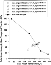
The temperature-dependent shear strength of the Al-Si alloy is shown by the solid dots in . Although a high sliding velocity induces a high local shear-strain rate, raising the hardness and hence the shear strength, work hardening is not considered here. The material strength at critical spots is determined using the calculated maximum asperity temperature.
FIG. 12 Maximum tangential traction and shear strength versus the maximum flash temperature, roughness, and friction coefficient.
Scuffing Failure Criterion
Based on the suggested scuffing mechanism, an improved criterion for scuffing failure is proposed as follows, indicating that scuffing failure would occur when the maximum surface tangential traction exceeds the modified shear strength.
Here, τ sm is the maximum surface tangential traction determined by the product of the frictional coefficient and the calculated average contact pressure, S m is the shear strength of the piston material corresponding to the maximum asperity temperature without considering work hardening, f* is a scuffing uncertainty factor designated as follows:
DISCUSSIONS ON SCUFFING MODELING
The production pistons and pins for a 4.6 L V8 2V four-stroke engine were used here for scuffing analyses. lists the bearing and lubricant parameters and the operating conditions used in the experiments. The oscillating surface velocity of the piston pin is shown in , and a measured surface after running-in is shown in . The scuffing load shown in is used for scuffing modeling and mapping.
TABLE 1 Bearing and Lubricant Parameters, and Operating Conditions for the Bench Tests
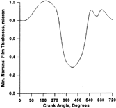
presents a typical variation of the minimum nominal film thickness in one load cycle. The valley value of the minimum film thickness in a cycle corresponds to the peak value of the applied load. Comparison between reveals that in one load cycle, mixed lubrication occurs at the peak load. The existence of the mixed lubrication may be explained by the minimum film thickness in , which is about the same in magnitude as the roughness of the bearing surface. Such an argument agrees well with the pictures of the scuffed bore surfaces given in in part I of this study (Zhang, et al. (Citation12)), where obvious wear and scuffing marks exist only near the center of the lower half of the bearing surface.
FIG. 11 Minimum film thickness in one cycle of load (1500 rpm).
The data plotted in are the results averaged from the tests under the same bearing geometry and operating conditions. The asperity frictional coefficient depends on the material pair and operating conditions, which is considered to be 0.1-0.2 for the current scuffing modeling based on knowledge about the frictional coefficients of the Al-Si alloy and steel in mixed lubrication and initial scuffing (Somi Reddy (Citation5); Wang, et al. (Citation27)).
FIG. 13 Scuffing uncertainty factor versus the maximum flash temperature, roughness, and friction coefficient.
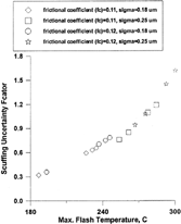
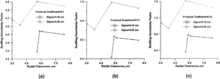
FIG. 14 Effects of frictional coefficient and bore surface roughness on the scuffing uncertainty factor. (a) Frictional coefficient = 0.10, (b) Frictional coefficient = 0.11 and (c) Frictional coefficient = 0.12.
show the calculated maximum surface tangential traction, measured bulk shear strength, and the scuffing uncertainty factor at the nominal bearing clearance versus the maximum asperity temperature for different coefficients of friction and roughnesses. These results are calculated based on the individually measured scuffing load, actual bearing geometric parameters, and the operating conditions of the bench tests. From these figures, one can see that the maximum surface tangential traction, the maximum asperity temperature, and the scuffing uncertainty factor increase significantly with the increases in roughness and the coefficient of friction. The scuffing uncertainty factor varies from about 0.3 to about 1.7 with the increase in the asperity temperature. The variation of the uncertainty factor suggests that the interaction among the factors that influence wear and scuffing, as well as modeling errors, is different for different test cases. also shows that the higher the maximum asperity temperature, the larger the uncertainty factor. It also reveals that the direct comparison between the maximum surface tangential traction and asperity temperature-dependent shear strength without considering the scuffing uncertainty is insufficient to predict scuffing failure.
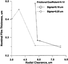
show the scuffing uncertainty factor as a function of frictional coefficient, bore surface roughness, and bearing radial clearance. Roughness significantly increases the scuffing uncertainty factor. For the case of the RMS roughness σ = 0.18 μm, there is a critical nominal bearing radial clearance (about C = 5.84 μm). Increasing the radial clearance causes the scuffing uncertainty factor to increase dramatically when C < 5.84 μm and then decrease when C > 5.84 μm. For the case of the RMS roughness σ = 0.25 μm, the variation of the scuffing uncertainty factor as a function of the bearing radial clearance is large. A minimum occurs at C = 3.81 μm, and a maximum appears at C = 5.588 μm. These trends correspond to those of the variation of the minimum nominal film thickness shown in , which represents the degree of contact severity. Although the coefficient of friction does not alter these trends, increasing the frictional coefficient increases the value of the scuffing uncertainty factor.
FIG. 15 Effect of bore surface roughness on minimum nominal film thickness.
It should be pointed out that the inaccuracy resulting from the use of the simplified lubrication and asperity temperature models in the pin/bore lubrication without considering the bearing thermoelastic deformation adds to the uncertainty of the scuffing analysis.
CONCLUSIONS
A scuffing criterion is developed based on the examination of surfaces and subsurfaces of scuffing test specimens, which states that scuffing failure would occur when the maximum surface tangential traction is larger than the modified shear strength. A scuffing uncertainty factor is introduced to reflect the influence of factors that affect wear and scuffing and the inaccuracy in modeling.
The research results indicate that the scuffing uncertainty factor increases as the maximum asperity temperature, frictional coefficient, and roughness increase. The effect of the radial clearance on the scuffing uncertainty factor is not linear, and the trends of variations correspond to those of the change of the minimum film thickness. The amplitudes of the uncertainty factor are also influenced by surface roughness and frictional coefficient.
ACKNOWLEDGMENTS
The authors are grateful for financial support by Karl Schmidt Unisia, Inc. and Ford Motor Company. QW would also like to thank USA National Science Foundation, Office of Naval Research and TTRF for support on her scuffing-related research.
Presented at the 55th Annual Meeting in Nashville, Tennessee May 7-11, 2000 Manuscript received by STLE February 25, 2002 Final manuscript approved August 24, 2003 Review led by Greg Kostrzewsky
Related Research Data
REFERENCES
- Blok , H. Oct. 13–15 . “Theoretical Study of Temperature Rise at Surfaces of Actual Contact under Oiliness Lubricating Conditions” . In Proc. of the General Discussion on Lubrication and Lubricants in London , Oct. 13–15 , 222 – 235 . The Institute of Mechical Engineers .
- Cuotiongco , E. C. and Chung , Y. W. 1994 . “Prediction of Scuffing Failure Based on Competitive Kinetics of Oxide Formation and Removal: Application to Lubricated Sliding of AISI 52100 Steel on Steel” . Tribol. Trans. , 37 : pp 622 – 628 .
- Johnson , R. R. , Dow , T. A. and Zhang , Y. Y. 1988 . “Thermoelastic Instability in Elliptic Contact Between Two Sliding Surfaces” . ASME J. Tribol. , 110 : pp 80 – 86 .
- Yang , J. , Cown , R. S. and Winer , W. O. 1993 . “Prediction of Failure Transitions in Sliding Contacts by a Thermomechanical Wear Model” . ASME J. Tribol. , 115 : pp 432 – 438 .
- Somi Reddy , A. , Pramila Bai , B. N. , Murthy , K. S. S. and Biswas , S. K. 1994 . “Wear and Seizure of Binary Al-Si Alloys” . Wear , 171 : pp 115 – 127 .
- Biswas , S. K. 1997 . “Sliding Wear of Materials” . Proc. of the First World Tribol. Conf. , : 159 – 175 .
- Greenwood , J. A. and Williamson , B. P. 1966 . “Contact of Nominally Flat Surfaces” . Proc. Roy. Soc. London, Ser. A. , 295 : pp 300 – 319 .
- Hirst , W. and Hollander , A. B. 1974 . “Surface Finish and Damage in Sliding” . Proc. Roy. Soc. London, Ser. A , 337 : pp 379 – 394 .
- Sheiretov , T. , Yoon , H. and Cusano , C. 1998 . “Scuffing under Dry Sliding Conditions—Part II: Theoretical Studies” . Tribol. Trans. , 41 ( 3 ) : pp 447 – 458 .
- He , X. 1998 . “Experimental and Analytical Investigation of the Seizure Process in Al-Si Alloy/Steel Tribocontacts,” , Northwestern University . Ph.D. diss.
- Yoon , H. , Sheiretov , T. and Cusano , C. 2001 . “Scuffing of Area Contacts under Starved Lubrication Conditions” . Tribol. Trans. , 44 : pp 435 – 446 .
- Zhang , C. , Cheng , H. S. , Qiu , L. , Knipstein , K. W. and Bolyard , J. 2003 . “Scuffing Behavior of Piston-Pin/Bore Bearing in Mixed Lubrication–Part I: Experimental Studies” . Tribol. Trans. , 46 ( 2 ) : pp 193 – 199 .
- Lim , S. C. and Asheby , M. F. 1987 . “Wear-Mechanism Maps” . Acta Metall. , 35 ( 1 ) : pp 1 – 24 .
- Booker , J. F. 1965 . “Dynamically Loaded Bearings: Mobility Method of Solution” . ASME J. Basic Eng. , : pp 537 – 546 .
- Goenka , P. K. 1984 . “Analytical Curve Fits for Solution Parameters of Dynamically Loaded Journal Bearings” . ASME J. Tribol. , 106 : pp 421 – 428 .
- Zhang , C. , Zhang , H. and Qiu , Z. 1999 . “Fast Analysis of Crankshaft Bearings with a Database Including Shear Thinning and Viscoelastic Effects” . Tribol. Trans. , 42 ( 4 ) : pp 922 – 928 .
- Paranjpe , R. S. and Han , T. Y. 1995 . “A Transient Thermohydrodynamic Analysis Including Mass Conserving Cavitation for Dynamically Loaded Journal Bearings” . ASME J. Tribol. , 117 : pp 369 – 378 .
- Piffeteau , S. , Souchet , D. and Bonneau , D. 2000 . “Influence of Thermal and Elastic Deformations on Connecting-Rod Big End Bearing Lubrication under Dynamic Loading” . ASME J. Tribol. , 122 : pp 181 – 191 .
- Shen , M. C. 1986 . “A Computer Analysis of Lubrication of Dynamically Loaded Journal Bearings Including Effects of Asperity Contacts,” , Northwestern University . master thesis
- Polonsky , I. A. and Keer , L. M. 2000 . “A Fast and Accurate Method for Numerical Analysis of Elastic Layered Contacts” . ASME J. Tribol. , 122 : pp 30 – 35 .
- Archard , J. F. 1959 . “The Temperature of Rubbing Surfaces” . Wear , 2 : pp 438 – 455 .
- Archard , J. F. and Rowntree , R. A. 1988 . “The Temperature of Rubbing Bodies, Part 2, The Distribution of Temperature” . Wear , 128 : pp 1 – 17 .
- Kuhlmann-Wilsdorf , D. 1987 . “Temperatures at Interfacial Contact Spot: Dependence on Velocity and on Role Reversal of Two Materials in Sliding Contact” . ASME J. Tribol. , 109 : pp 321 – 329 .
- Qiu , L. and Cheng , H. S. 1998 . “Temperature Rise Simulation of Three-Dimensional Rough Surfaces in Mixed Lubricated Contact” . ASME J. Tribol. , 120 : pp 310 – 318 .
- Wang , Q. and Cheng , H. S. 1995 . “A Mixed Lubrication Model for Journal Bearings with a Soft Coating, Part I: Contact and Lubrication Analysis” . Tribol. Trans. , 38 : pp 654 – 662 .
- Wang , Q. and Cheng , H. S. 1995 . “A Mixed Lubrication Model for Journal Bearings with a Soft Coating, Part II: Flash Temperature Analysis and Its Application to Tin Coated Al-Si Bearings” . Tribol. Trans. , 38 : pp 517 – 524 .
- Wang , Y. , Zhang , C. , Wang , Q. and Lin , C. 2001 . “TEHD Analyses of Journal Bearing under Severe Operating Conditions” . Tribol. Int. , 35 : pp 395 – 407 .