Abstract
The present study extends the full numerical EHL solution to wide parameter ranges that cover practical and severe operating conditions commonly found in heavy-duty components. This article is the fourth part of the present study, and is focused on the effect of material properties on the film thickness, following three previous papers that investigated the effects of speed, load, and contact geometry, respectively. In this article, the pressure-viscosity coefficient is varied in a range from zero to 72.8 GPa−1 and the elastic modulus from 80 to 400 GPa, sufficiently wide to cover different materials and lubricants commonly used in industries. More than 500 cases have been analyzed, and results show that in the extended parameter ranges the relationships between the material properties and the film thickness still primarily follow the simple power rules proposed by the conventional EHL theory. However, the exponents in the power-law functions no longer appear to be constants. They are indeed functions of speed and load. For the relationship between the pressure-viscosity coefficient and the central film thickness, the exponent appears to be quite close to 0.53 proposed by the Hamrock-Dowson formula if the speed and the load are moderate. When the speed is low and/or the load is heavy, this exponent may be considerably greater. The same trend is observed for the relationship between the elastic modulus and the film thickness. At moderate loads and speeds, the exponent is close to −0.073, which is used in the Hamrock and Dowson formula. When the speed is decreased and/or the load increased, the exponent may become positive. It is found, in addition, that the exponents in these relationships are only weakly affected by contact ellipticity.
INTRODUCTION
Engineering research on elastohydrodynamic lubrication (EHL) has been seriously challenged by ever tougher requirements for more severe operating conditions, more compact sizes of products and their components, better operational efficiency and longer service life/lower warranty costs, as well as newer materials used in industries. It is necessary, therefore, to extend parameter ranges in the EHL study to cover practical, severe, and sometimes extreme conditions commonly found in functional components, such as gears, rolling bearings, cams and followers, and traction drives/CVTs, etc. Better-developed computer technologies and improved numerical solution methods have made it possible to overcome difficulties associated with strong non-linearity/instability in the EHL numerical solution under severe/extreme conditions. Analyzing a large number of cases also becomes possible, as the computation speed has been tremendously increased in the last 5-10 years.
In the present study, more than fifteen hundred cases have been analyzed and the range of entraining speed has been greatly extended to cover more than nine orders of magnitude (Zhu (Citation1)), and that of applied load more than six orders (Zhu (Citation2)). It has been found that for moderate loads and speeds, where the conventional EHL theory (Hamrock and Dawson (Citation3-5); Chittenden (Citation6)) was originally developed, the present results agree well with the conventional film thickness formulae. When the load is extremely light and the speed is high, the present results are close to those predicted by Martin's hydrodynamic theory (Zhu (Citation2)). If the speed is extremely low and/or the load extremely heavy, the present solution approaches that from the Hertzian dry contact theory due to vanishing hydrodynamic action (Zhu (Citation1)-(Citation2); Zhu and Hu (Citation7); Hu and Zhu (Citation8)). This confirms that the mathematical model used in the present work is valid over the extended parameter ranges. Basically, in such extended ranges the relationships between the operating conditions (load and speed) and the film thickness may no longer follow the simple power rules; see (Zhu (Citation1)-(Citation2)) for details. Also, it has been found that the parameters do not influence the film thickness independently. The effect of load, for instance, is considerably dependent upon the speed. Such effect is weak if the speed is high and may be significantly stronger if the speed is low. Since the parameter ranges are greatly extended, and the assumption of parameter independence is no longer valid, a large number of cases must be analyzed in order to investigate the EHL behavior with carefully considered mutual dependence among all the parameters.
| a, b | = |
semi-axes of Hertzian contact ellipse in the x and the y directions, respectively |
| C, D | = |
constants in power law relationship [8] |
| E′ | = |
effective elastic modulus |
| G* | = |
α E′, dimensionless material parameter |
| h | = |
local film thickness (or gap) |
| h c | = |
central film thickness |
| H | = |
h/a, dimensionless film thickness (used in ) |
| H c | = |
h c /R x , dimensionless central film thickness |
| k | = |
b/a, contact ellipticity parameter |
| n | = |
constant in viscosity model [3] (power law) |
| p | = |
pressure |
| P H | = |
maximum Hertzian pressure |
| p t | = |
break pressure in viscosity model [7] (two-slope law) |
| Q | = |
exponent in power law relationship [9] |
| R x , R y | = |
effective radii of curvature in the x and the y directions, respectively |
| S | = |
constant in power law relationship [9] |
| U | = |
rolling velocity |
| U* | = |
η o U/(E′ R x ), dimensionless speed parameter |
| W | = |
load |
| W* | = |
W/(E′ R x 2), dimensionless load parameter |
| x, y | = |
coordinates (x coincident with the rolling direction) |
| X, Y | = |
dimensionless coordinates, X = x/a and Y = y/b |
| Z | = |
pressure-viscosity index in viscosity model [5] (Roelands' law) |
| α | = |
pressure-viscosity exponent |
| α2 | = |
2nd pressure-viscosity coefficient in viscosity model [7] (two-slope law) |
| η | = |
viscosity |
| η o | = |
viscosity under ambient condition |
| θ | = |
constant in viscosity model [3] (power law) |
It has been well understood that material properties, mainly including the viscosity, the pressure-viscosity relationship, and the effective elastic modulus of solid bodies, could significantly affect the EHL film formation. Compared with these three parameters, the non-Newtonian behavior of lubricant does not typically have significant influence on the film thickness (Kim and Sadeghi (Citation9)). Since in an isothermal EHL equation system the ambient viscosity, η o , mathematically plays the same role as the entraining speed (or commonly called “the rolling speed”), U, they are always combined together in the same non-dimensional speed parameter. The effect of the ambient viscosity, therefore, is the same as that of the speed, which has been studied by previous papers and recently by the present work (Zhu (Citation1)). The investigation on the effect of material properties, therefore, will be focused on the other two parameters, the pressure-viscosity relationship and the effective elastic modulus.
Although the effect of material properties on the film thickness appears to be significant, it has not been thoroughly studied. In the milestone paper by Hamrock and Dowson (Citation5), only four numerical cases were analyzed in a non-dimensional material parameter range from G* = 2310 to 6785. Based on these four cases for the two variables (the pressure-viscosity coefficient and the effective elastic modulus), an exponent of 0.53 was obtained from curve fitting and then adopted in Hamrock-Dowson's central film thickness formula (Citation5). Few other systematic studies on this topic have been found in published literature since then.
In industrial applications, however, the material properties may be varied in much wider ranges. For commonly used engineering materials, the elastic modulus could be as low as 70 GPa (bronze and aluminum alloys) and 100-110 GPa (titanium alloys), or as high as 310-400 GPa (ceramics such as Si3N4 and Al2O3). In the meantime, typical pressure-viscosity coefficients at ambient temperature for mineral oils and synthetic lubricants are usually in a range of 10∼50 GPa−1. However, considering the fact that the pressure-viscosity coefficients are usually dependent upon the operating temperature, they may be reduced down to 5 GPa−1 or less at elevated temperatures, or increased to 70 GPa−1 or higher at low temperatures. It is necessary, therefore, to extend the parameter ranges and further investigate the effect of material properties on the EHL film thickness, especially under severe operating conditions. Since the influence of material properties may be quantitatively or even qualitatively dependent upon other parameters, such as the load and the speed, a large number of cases need to be analyzed in order to obtain reliable conclusive results.
This article is the fourth part of the present study, focusing on the effect of material properties on the lubricant film thickness, following three previous papers (Zhu (Citation1), (Citation2), (Citation10)) that investigated the effects of speed, load, and contact geometry, respectively. In this article, more than 500 cases have been analyzed at different loads, speeds, and contact ellipticity values, while the pressure-viscosity coefficient is varied from zero to 72.8 GPa−1, and the elastic modulus from 80 to 400 GPa. The non-dimensional material parameter, G*, is consequently in a range from zero to 16,000. These parameter ranges are believed to be sufficiently wide for most engineering applications. For several reasons explained in detail in the previous papers of the present study (Zhu (Citation1), (Citation2), (Citation10)), only point contact (or elliptical contact) cases are analyzed, and attention is primarily given only to the results of central film thickness. The results will be discussed and compared with those predicted by the conventional EHL theory, which is well represented by the following Hamrock-Dowson central film thickness formula (Citation5):
It should also be mentioned that the present work assumes that the material properties and relevant models are given as input data. This article does not intend to investigate, for example, how accurate commonly used viscosity models are under different conditions. Our effort is focused on studying the effect of material properties on the EHL film thickness through computational analysis based on given pressure-viscosity relationships.
BASIC EQUATIONS AND NUMERICAL PROCEDURE
The basic equations for the point contact EHL and the recently developed numerical solution method have been repeatedly presented in (Zhu and Hu (Citation7); Hu and Zhu (Citation8)) and a few other papers. They will not be repeated in this article in order to concentrate on the discussion of the numerical results and their physical significance. During the computation, the EHL solution domain size may be adjusted, when necessary, in order to ensure a fully flooded condition (see (Zhu (Citation1,Citation 2)) for details). For the purpose of easy comparison, Hamrock and Dowson's dimensionless parameters, G*, U*, W*, k and H c , are employed unless otherwise noticed. Note that in the present article “H&D” stands for “Hamrock and Dowson.”
DIFFERENT PRESSURE-VISCOSITY RELATIONSHIPS
There are several different pressure-viscosity relationships that have been commonly used in the EHL studies. The most widely used relationship is the Barus equation presented in 1893 (Barus (Citation11)), which, in its isothermal form, reads,
In principle, constants θ and n can be estimated experimentally, and this relationship may be considerably more accurate if reliable testing data are available. Due to a lack of testing data, Cameron suggested n = 16 for commonly used oils, and θ can be estimated with the following formula based on an assumption that EquationEqs. [2] and [3] agree with each other and yield the same viscosity if the pressure is low:
Another commonly used relationship was presented by Roelands in his Ph.D. thesis in 1966 (Citation13). Under the isothermal condition, it can be expressed in SI unit system as
For the pressure in excess of 1 GPa, EquationEqs. [3] and [5] might not be able to give satisfactory prediction. Based on experimental results, Allen, et al. (Citation14) proposed a two-slope exponential model that reads,
In order to investigate the effect of different viscosity models, several numerical cases have been analyzed at different speeds, loads, and contact ellipticity values but with the same material properties. Some results of calculation are summarized in . Note that the pressure-viscosity coefficient in the Barus EquationEq. [2] and the two-slope model, EquationEq. [7], is chosen as α = 18.2 GPa−1, and other parameters, θ and Z, used in the power law EquationEq. [3], and the Roelands model, EquationEq. [5], are estimated according to Formulae [4] and [6]. Correspondingly, the dimensionless material parameter G* is 4000. The second pressure-viscosity coefficient α2 is 2.0 GPa−1 and the break pressure p t is 230 MPa. It can be seen from that generally the effect of different viscosity models appears to be insignificant. The power law and the Roelands equation may yield slightly smaller film thickness, especially when the load is heavy (see the results for Case No. 5). However, the largest difference in predicted film thickness did not exceed 6-7% in all the cases analyzed. Actually, in most cases the discrepancies were within a few percent, which can be considered negligible in most engineering practice. The insignificant influence on the film thickness may be due to the fact that the EHL film thickness is dominated by the entraining action in the inlet zone, where the hydrodynamic pressure is still low. At low pressure in the inlet zone, the different models yield nearly the same viscosity, although large differences could be found in the contact zone.
TABLE 1 Comparison of Film Thickness Results from Different Viscosity Models
The Barus model, EquationEq. [2], is chosen for the majority of cases analyzed in the present study for the following reasons:
| 1. | The effect of different pressure-viscosity models on the central film thickness appears to be limited or, in most cases analyzed, negligible. | ||||
| 2. | Most available experimental data were obtained and presented based on the Barus model. | ||||
| 3. | The Barus model has been the most commonly used one. Therefore, a good consistency with most previous studies can be kept. | ||||
RESULTS AND DISCUSSION
Cases Analyzed
In order to study the effect of material properties on the film thickness in the extended speed, load, and ellipticity ranges, some parameters are fixed for all the cases analyzed in the present article. These include R x = 19.005 mm, η o = 0.096 Pa.s, and Poisson's ratio of 0.3. The other geometric parameter, R y , is either 19.005 mm for a circular contact, k = 1, or 474.84 mm for a long elliptical contact, k = 8, which can be practically considered as a “line contact.” There will be four different levels of rolling speed, 15 m/s, 2.5 m/s, 0.625 m/s, and 0.1 m/s, with the dimensionless speed parameter ranging from U* = 0.22984 × 10⁻¹¹ to 0.34476 × 10⁻⁹. The applied load will be varied so that four levels of maximum Hertzian pressure, P H = 0.6789 GPa, 1.0777 GPa, 1.7108 GPa, and 2.7156 GPa, can be achieved. The reason why the load, the speed, and the contact ellipticity are changed is that the assumption of parameter independence has been removed in the present study, and the effort is to investigate whether the effect of material properties depends on the other parameters or not. For each possible combination of load, speed, and contact ellipticity, the pressure-viscosity coefficient is changed from zero (for iso-viscous lubricants) to 72.8 GPa−1 (for strong piezo-viscous lubricants), and the elastic modulus of the two solids varied from 80 to 400 GPa, as mentioned above. Note that while keeping the maximum Hertzian pressure constant, the applied load needs to be changed with different contact ellipticity values (see (Zhu (Citation10)) for details), and the dimensionless load parameter, W*, will not be constant.
RESULTS FOR THE EFFECT OF PRESSURE-VISCOSITY COEFFICIENT
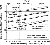
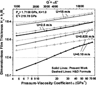
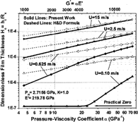
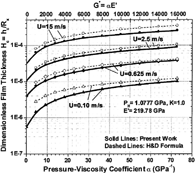
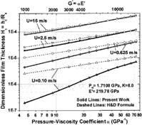
More than 300 cases have been analyzed through full numerical solutions for investigating the effect of the pressure-viscosity coefficient under different loads and speeds in both circular and long elliptical contacts. In these cases, the effective elastic modulus has been kept constant, E′ = 219.78 GPa, for commonly used steels. Corresponding to the range of pressure-viscosity coefficient from zero to 72.8 GPa−1, the dimensionless material parameter, G* = α E′, is varied proportionally from zero to 16,000. From these numerical cases, consistent trends have been found, and some typical results are illustrated with solid lines in , in comparison with dashed lines from the H&D Formula [1].
FIG. 1(a) Effect of pressure-viscosity coefficient at different loads and speeds (K = 1). Results at k = 1 and P H = 0.6789 GPa.
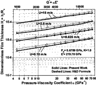
FIG. 2(a) Effect of pressure-viscosity coefficient at different loads and speeds (K = 8). Results at k = 8 and P H = 1.0777 GPa.
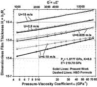
reveal that in the extended parameter ranges all the solid lines from the present work are remarkably straight on a log-log scale. This indicates that the relationship between the pressure-viscosity coefficient, α (or represented by G*), and the central film thickness, H c , primarily follows a simple power law, which can be expressed as follows:
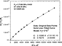
Because the present results in and are plotted on the log-log scale, the data for iso-viscous fluids (α = G* = 0) do not show up. Actually, even for α = G* = 0, there may still be a significant lubricant film that can be observed from , which is exactly the same figure as but linear scales are used for α and G*. It is also important to note that in the calculated film thickness could be extremely small due to the combination of heavy load and low speed. If it is smaller than a certain low limit, say 1.5 nm for the cases in , it can be practically considered as a zero EHL film. This is because when the film is at the scale of lubricant molecules, the hydrodynamic action based on the fluid continuity may vanish and the pressure distribution should approach that of dry contact (see (Citation1,Citation2) for more detailed description).
Note that illustrates the results for the circular contact, k = 1, and shows some typical cases for the long elliptical contact, k = 8. The comparison of with and with indicates that, at the same speed and the same Hertzian pressure, differences in the slopes of those straight lines appear to be relatively insignificant. This means that the influence of the pressure-viscosity coefficient on the film thickness is quite strongly dependent upon the load and the speed, but not the contact ellipticity.
Curve fitting has been conducted based on the power law relationship expressed by EquationEq. [8], in order to determine the values of exponent D under different conditions. shows the curve-fitting results for a set of sample cases at k = 8, P H = 1.7108 GPa, and U = 0.625 m/s. It is observed that the fitted curve nicely follows all the original data points from the present work. The exponent, D, is found to be 0.78276, considerably larger than 0.53 in the H&D Formula [1]. summarizes the results of exponent D from curve fitting at different speeds, contact pressure levels, and contact ellipticity values. It can be clearly seen that D is a strong function of speed and load, but a relatively weak function of contact ellipticity, especially when the speed is not high.
TABLE 2 Curve Fitting Results for Exponent D Under Different Conditions
RESULTS FOR THE EFFECT OF EFFECTIVE ELASTIC MODULUS
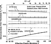
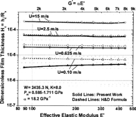
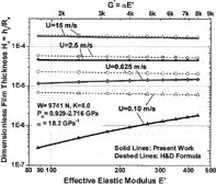
About 200 cases have been analyzed for studying the effect of effective elastic modulus under different loads and speeds in both circular and long elliptical contacts. In these cases the pressure-viscosity coefficient has been kept constant, α = 18.2 GPa−1, which is typical for mineral oil-based transmission fluids in a common operating temperature range of 120-160°C. Corresponding to the range of elastic modulus from 80 to 400 GPa, the dimensionless material parameter, G* = α E′, is varied proportionally from 1600 to 8000. From these numerical cases, consistent trends have been found, and some typical results from the present work are illustrated with solid lines in , in comparison with dashed lines from the H&D Formula [1].
FIG. 4(a) Effect of effective elastic modulus at different loads and speeds. Results at k = 1 and W = 200 N.
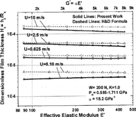
It is observed from that in the extended parameter ranges, all the solid lines from the present work are remarkably straight on a log-log scale. This indicates that the relationship between the effective elastic modulus, E′ (or represented by G*), and the central film thickness, H c , primarily follows a simple power law, which can be written as follows:
Note that illustrate the results for the circular contact, k = 1, and present some typical cases for the long elliptical contact, k = 8. Comparing with and with , one can see that at the same speed and in the same range of Hertzian pressure, differences in the slopes of those straight lines appear to be relatively less noticeable. Again, the influence of the elastic modulus on the film thickness is dependent strongly upon the load and the speed, but not as strongly upon the contact ellipticity, as shown in , which summarizes curve fitting results for exponent Q in the power law relationship, EquationEq. [9].
TABLE 3 Curve-Fitting Results for Exponent Q Under Different Conditions
SAMPLE SOLUTIONS
Six sample cases at a fixed speed, load, and contact ellipticity, as well as a constant effective elastic modulus, U* = 0.14365E-10, W* = 0.10078E-4, k = 1, E′ = 219.78 GPa, but with different pressure-viscosity coefficients, are illustrated in . These cases demonstrate the effect of the pressure-viscosity coefficient on the film thickness contours and the pressure distributions in detail. It can be seen that, when the lubricant is iso-viscous, α = 0, the film thickness is relatively small, and, in this specific case, the two surfaces are partially in contact on the outlet side of the Hertzian contact zone. In the meantime, the pressure distribution is quite close to Hertzian. As the pressure-viscosity coefficient continuously increases the EHL film becomes thicker due to the enhanced piezo-viscous influence. Also, some typical EHL characteristics, such as side lobes and the secondary pressure spike, may be more clearly observed. Note that in , as well as in , a differently defined dimensionless film thickness, H = h/a, is used when plotting the results.
FIG. 5 Sample solutions at different pressure-viscosity coefficients. U* = 0.14365E-10, W* = 0.10078E-4, k = 1, E′ = 219.78 GPa, P H = 1.711 GPa.
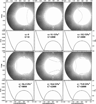
FIG. 6 Sample solutions at different effective elastic moduli. U = 2.5 m/s, W = 800 N, k = 1, α = 18.2 GPa−1.
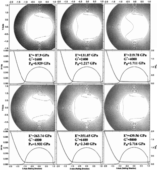
Another six sample solutions at U = 2.5 m/s, W = 800 N, k = 1, and α = 18.2 GPa−1, but different elastic moduli, are given in , showing the effect of elastic modulus on EHL solutions. Compared with the cases in , changes in the pressure distribution and the film thickness contour appear to be less significant. Note that, as the effective elastic modulus is changed, the dimensionless load and speed parameters, U* and W*, as well as the Hertzian pressure, are no longer constant even though the dimensional load and the speed are fixed.
CONCLUSIONS
An investigation has been conducted through full numerical EHL solutions in extended speed and load parameter ranges for the effect of material properties on the central film thickness. The results are compared with those estimated by the conventional EHL theory. The contact ellipticity is also changed between 1 and 8. Consistent trends have been found from more than 500 numerically analyzed cases, based on which the following conclusions can be drawn:
| 1. | The effect of different pressure-viscosity models on the EHL film thickness has been studied and found to be limited or, in most analyzed cases, negligible. | ||||
| 2. | The present results in the extended parameter ranges show that the relationships between the central film thickness and the material properties primarily follow simple power laws proposed by the conventional EHL theory. The H c -α and Hc-E′ curves on the log-log scales plotted based on the present results appear to be straight lines. | ||||
| 3. | Quantitatively, the current results also agree with the conventional film thickness formula in the relatively narrow parameter ranges where the conventional formula was originally developed. For example, when the hydrodynamic influence is moderate, exponent D in the relationship between the pressure-viscosity coefficient and the central film thickness appears to be quite close to 0.53 used in the Hamrock and Dowson formula. Exponent Q for the relationship between the elastic modulus and the film thickness, in the same way, is fairly close to −0.073 employed by the conventional theory. | ||||
| 4. | However, in the extended parameter ranges, exponents D and Q in those power-law relations do not appear to be constants. They are indeed functions of the speed, the load and the contact ellipticity. When the speed is high and/or the load is light, exponent D in the H c -α relationship may become smaller due to enhanced hydrodynamic action. On the contrary, D may be considerably greater than 0.53 if the speed is low and/or the load is heavy. | ||||
| 5. | A similar trend is observed for exponent Q in the Hc-E′ relationship. Q may take a greater negative value if the speed is high and/or the load is light. On the contrary, Q may take a smaller negative value, or even turn to be positive, if the speed is significantly reduced and/or the load increased. | ||||
| 6. | The influence of contact ellipticity on these exponents, D and Q, is relatively small, compared to the influence of speed and load. | ||||
ACKNOWLEDGMENTS
The author would like to express his sincere gratitude to the continuous support by Mr. Bohdan Lisowsky and Mr. John Bair of Eaton Corporation.
Presented at the STLE/ASME Tribology Conference in Ponte Vedra Beach, Florida October 27-29, 2003 Final manuscript approved August 28, 2003 Review led by Steve Danyluk
REFERENCES
- Zhu , D. 2002 . “Elastohydrodynamic Lubrication in Extended Parameter Ranges—Part I: Speed Effect” . Trib. Trans. , 45 : pp 540 – 548 .
- Zhu , D. 2002 . “Elastohydrodynamic Lubrication in Extended Parameter Ranges—Part II: Load Effect” . Trib. Trans. , 45 : pp 549 – 555 .
- Hamrock , B. J. and Dowson , D. 1976 . “Isothermal Elastohydrodynamic Lubrication of Point Contacts, Part 1—Theoretical Formulation” . ASME Jour. of Lubr. Tech. , 98 : pp 223 – 229 .
- Hamrock , B. J. and Dowson , D. 1976 . “Isothermal Elastohydrodynamic Lubrication of Point Contacts, Part 2—Ellipticity Parameter Results” . ASME Jour. of Lubr. Tech. , 98 : pp 375 – 383 .
- Hamrock , B. J. and Dowson , D. 1977 . “Isothermal Elastohydrodynamic Lubrication of Point Contacts, Part 3—Fully Flooded Results” . ASME Jour. of Lubr. Tech. , 99 : pp 264 – 276 .
- Chittenden , R. J. , Dowson , D. , Dunn , J. F. and Taylor , C. M. 1985 . “A Theoretical Analysis of the Isothermal Elastohydrodynamic Lubrication of Concentrated Contacts, Part I: Direction of Lubricant Entrainment Coincident with the Major Axis of the Hertzian Contact Ellipse” . Proc. of the Royal Society, London, A , 397 : pp 245 – 269 .
- Zhu , D. and Hu , Y. Z. 1999 . “The Study of Transition from Full Film Elastohydrodynamic to Mixed and Boundary Lubrication” . Proc. of 1999 STLE/ASME H.S. Cheng Tribology Surveillance , : pp 150 – 156 .
- Hu , D. and Zhu , D. 2000 . “A Full Numerical Solution to the Mixed Lubrication in Point Contacts” . ASME Jour. of Trib. , 122 : pp 1 – 9 .
- Kim , K. H. and Sadeghi , F. 1991 . “Non-Newtonian Elastohydrodynamic Lubrication of Point Contact” . ASME Jour. of Trib. , 113 : pp 703 – 711 .
- Zhu , D. 2002 . “Elastohydrodynamic Lubrication in Extended Parameter Ranges, Part III: Contact Ellipticity Effect,” . Trib. Trans , submitted to, for publication
- Barus , C. 1893 . “Isothermals, Isopiestics and Isometrics Relative to Viscosity” . American Jour. of Science , 45
- Cameron , A. 1966 . Principles of Lubrication , Longman Press .
- Roelands , C. J. A. 1966 . “Correlation Aspects of the Viscosity-Temperature-Pressure Relationship of Lubrication Oils,” , The Netherlands : Technische Hogeschool Delft . Ph.D. Thesis
- Allen , C. W. , Townsend , D. P. and Zaretsky , E. V. 1970 . “Elastohydrodynamic Lubrication of a Simple Ball in a Non-Conforming Groove” . ASME Jour. of Lubr. Tech. , 92 : pp 89 – 96 .
- Dowson , D. and Higginson , G. R. 1961 . “New Roller-Bearing Lubrication Formula” . Engineering (London) , 192 : pp 158 – 159 .
