Abstract
Tracer dilution methods are commonly used to measure discharge in steep mountain streams. This research addressed knowledge gaps associated with dilution methods using original field data collected on nine streams in southwest British Columbia and discharge measurements conducted by Northwest Hydraulic Consultants Ltd. Minimum mixing lengths ranged between 2.4 and 24.5 stream wetted widths, but determining the mixing length can be confounded by surface-subsurface water fluxes. Probes need to be placed on opposite sides of the stream to verify adequate mixing, because probes located at different locations on the same of the stream sometimes suggested complete mixing had occurred when it in fact had not. For probes located downstream of complete mixing, breakthrough curves (BTCs) for probes located in the main current differed significantly from probes in zones with recirculating flow, even though they yielded discharge values within ± 10%. The peak of the BTC is a function of the mass of tracer injected, reach length, channel cross-sectional area, and the integral of a non-dimensional BTC, A*. The distribution of A* derived from analysis of 175 BTCs can be used, in conjunction with estimates of channel geometry and desired increases in electrical conductivity, to estimate dosing requirements to avoid under- or over-dosing a stream reach.
Les méthodes de dilution avec traceur sont couramment utilisées pour mesurer le débit des cours d’eau de montagne avec pentes escarpées. Cette recherche visait à combler le manque de connaissances associé aux méthodes de dilution en utilisant les données de terrain pour neuf cours d’eau dans le sud-ouest de la Colombie-Britannique et les mesures de débits réalisées par la Northwest Hydraulic Consultants Ltd. Les longueurs de mélange minimum se situent entre 2.4 et 24.5 des largeurs mouillées du ruisseau, mais la détermination de la longueur de mélange peut être rendue plus confuse par les courants d’eau surface/sous-surface. Des capteurs doivent être placés de chaque côté du cours d’eau pour vérifier l’adéquation du mélange puisque les capteurs installés à différents endroits sur le même côté d’un cours d’eau peuvent parfois suggérer un mélange complet alors que ce n’est pas le cas. Pour ce qui est des capteurs situés en aval du mélange complet, les courbes de restitution des capteurs dans le courant principal différaient beaucoup de ceux se trouvant en zones de débit de recirculation, même s’ils ont tout de même permis d’évaluer les valeurs de débits à ± 10 %. Le pic de la courbe de restitution est une fonction de la masse du traceur injectée, de la longueur du tronçon, de l’aire de la section transversale du canal et de l’intégrale d’une courbe de restitution non dimensionnelle, A*. La distribution de A*, provenant de l’analyse de 175 courbes de restitution, peut être utilisée, conjointement avec les estimations de la géométrie des canaux et des hausses de la conductivité électrique désirées, afin d’estimer le dosage approprié pour éviter un sous-dosage ou un surdosage d’un tronçon de cours d’eau.
Introduction
In the last decade, there has been increasing attention within both the operational and research communities to quantifying the uncertainties in streamflow data to increase the accuracy of rating curves, hydrologic model calibration and other hydrologic procedures such as flood frequency analysis (e.g. Liu et al. Citation2009; McMillan et al. Citation2012; Westerberg et al. Citation2011). The uncertainty associated with a streamflow record arises from uncertainties in the discharge measurements, the measurement of stage, and the rating curve (Hamilton and Moore Citation2012). Field discharge measurements may be prone to high uncertainty, and factors that affect uncertainty include field conditions, practitioner experience and the method used for discharge measurement.
The velocity-area method via current metering or acoustic Doppler current profiling is the most common method for discharge measurement, and its accuracy has been well established (e.g. Herschy Citation1975; Pelletier Citation1988; Oberg and Mueller Citation2007). However, this method may be impractical or subject to great uncertainties for steep stream reaches due to complex channel geometries. Dilution gauging via stream tracers is an alternative approach that is particularly well suited for steep, rough streams that cannot be gauged accurately using the velocity-area method (Moore Citation2005).
Dilution gauging has been growing in use due to the increasing need to monitor discharge in steep mountain streams – for example, for planning and managing run-of-river hydro-electric projects that are typically sited on steep streams (Kerr Wood Leidal Associates, Ltd. Citation2007), and for scientific studies that focus on the hydrology of headwater streams (e.g. Gomi et al. Citation2002; Kelleher et al. Citation2013; Ward et al. Citation2013). The method has been shown to be accurate to within ± 4–7% for suitable stream reaches (Day Citation1977; Moore Citation2004) and is applicable to a wide range of stream sizes, from small first-order streams (Q 1–10 L·s−1) to large rivers (Q 100–1000 m·s−1) (González-Pinzón et al. Citation2013). In addition, analysis of tracer breakthrough curves (BTCs) can be used to compute travel time distributions and hence to determine quantities such as mean velocity (Waldon Citation2004; Zimmermann Citation2010), frictional resistance (Lee and Ferguson Citation2002; Comiti et al. Citation2007), and transient storage characteristics (Szeftel et al. Citation2011; Jiménez and Wohl Citation2013).
The most commonly used in-stream tracers are salt and Rhodamine WT. Rhodamine WT is detectable at much higher dilutions than salt, and thus can be used to gauge higher discharges than is feasible with salt. However, there are concerns when using Rhodamine WT for discharge measurements because sorption to the streambed and to suspended sediment would generate bias (Runkel Citation2015). Also, salt is preferred in many situations because it is widely available at relatively low cost, and can be readily detected through its influence on electrical conductivity (EC), allowing the use of lower cost conductivity probes over more expensive fluorometers.
One of the most critical factors governing the accuracy of stream gauging by dilution methods is the requirement that the tracer be fully mixed across the stream at the measurement location. A range of models have been proposed to determine mixing lengths based on hydraulic and geometric parameters of the stream (e.g. Glover Citation1964), and the application of one-dimensional advection-diffusion models (e.g. Fischer Citation1966; Ward Citation1973; Yotsukura and Cobb Citation1972). Based on studies on steep mountain streams, Day (Citation1977) recommended that the mixing length (xm) should equal or exceed 25 wetted stream widths (w) to ensure complete mixing. However, the mixing characteristics of a stream depend on its geomorphic properties as well as the flow level, suggesting that a universal mixing length (xm = 25·w) may not be accurate for all streams and all flow levels. Furthermore, in some streams it may be impossible to find a suitable stream reach that is long enough to accommodate Day’s standard (e.g. due to tributary inflow, or safety/accessibility).
Complete mixing can be readily assessed for constant-rate injection by moving the probe across the stream once steady-state conditions have been achieved (Moore Citation2004). However, constant-rate injection is generally limited to lower flows and requires a pump or other equipment to inject the tracer solution. Therefore, slug injection is often preferred for both research and operational purposes. For the slug injection method, adequate mixing is typically confirmed by comparing discharge measurements from two different measurement locations for the same tracer injection. If the measurements agree within some specified tolerance (based on the estimated uncertainty of the calculated discharges), then the mixing length is considered adequate. Ideally, the measurement locations are on opposite sides of the stream. However, in cases where it is not possible to access both banks of a stream, probes may be placed at different distances downstream of the injection point (Moore Citation2005). Determination of the mixing length with this approach can be complicated by groundwater discharge and/or tracer loss along hyporheic flow paths, which result in a progressive increase in tracer dilution with distance downstream (Zellweger et al. Citation1989; Clow and Fleming Citation2008).
A related issue that does not appear to have been discussed in the literature is the sensitivity of streamflow measurement to probe location. Some authors recommended that the probe be placed within the main current of the channel (Moore Citation2005). In many situations, however, it may not be possible to locate the probe in the main current. Furthermore, if the flow is aerated, the BTC will include abrupt drops and jumps as air bubbles pass through the probe. For these reasons, some practitioners routinely place their probes along the side of the channel in zones with reduced aeration.
A key issue with streamflow measurement by slug injection of salt is determining the quantity of tracer to inject during an experiment, as there must be enough injected to ensure an adequate response for accurate measurements (Moore Citation2005) while minimizing the potential for deleterious ecological impacts (Wood and Dykes Citation2002). The minimum dosage necessary is dependent on the stability of the measurement reading, the precision of the measurement probe, the desired increase in tracer concentration and the mixing characteristics of the stream. For example, a stream with less longitudinal dispersion induces a more concentrated salt wave with a higher peak concentration, and requires less injection volume (Moore Citation2005). A range of approaches for determining salt dosage for stream gauging are summarized in Table . Moore (Citation2005) suggested conducting trial injections with a small volume or mass, and then increasing the volume or mass as necessary. However, this trial-and-error approach requires more time and more salt, and a reliable method for determining salt dosage would increase efficiency.
Table 1. Salt dilution dosage guidelines from various sources.
The objective of this study was to contribute to the development of improved protocols for tracer injection methods for mountain streams by addressing the following questions: (1) how reliable are current approaches to assessing adequate mixing length for a stream reach; (2) how sensitive is the discharge measurement to location along or across the stream channel; (3) can dosage guidelines be developed based on geomorphic and/or geometric properties of the stream channel and desired increases of peak EC over background EC?
Study sites and methodology
Study sites
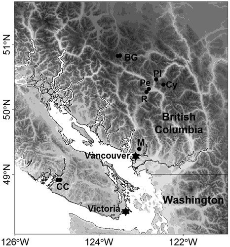
The study focused on streams that are appropriate for stream gauging via salt dilution, which are small to intermediate size (typical discharges of less than 10 m3·s−1) with gradients exceeding 2% and channel morphologies ranging from riffle-pool to cascade (Table ). Study streams were located in the southern Coast Mountains of British Columbia and Vancouver Island (Figure ).
Table 2. Characteristics of stream reaches used in the study.
Figure 1. Locations of study stream sites (black circles) in British Columbia. Sites are identified as follows: BG – Bridge Glacier watershed (Bridge Glacier West Creek and Bridge Glacier South Creek); Pl – Place Creek; Cy – Cayoosh Creek, Pe – Pemberton Creek; R – Rutherford Creek; M – Mosquito Creek; CC – Carnation Creek watershed (Carnation Creek Tributary C and Carnation Creek Tributary L).
Field methods
Tracer injections were performed to determine stream discharges as well as to study the mixing dynamics of the streams. The dry mass slug injection method (Hudson and Fraser Citation2005) and the salt-in-solution slug injection method (Moore Citation2005) were used. Dry injection was used for higher flows when more salt was needed and rapid dissolution of the salt could be ensured. Slug injection with salt-in-solution was used for lower flows.
Dry mass injection is performed by injecting a known mass of salt upstream and measuring the change in temperature-corrected electrical conductivity (ECT, μS·cm−1) at a point downstream of the injection point. Prior to injection, the background ECT (ECBG) of the ambient stream water is measured. After injection, ECT is recorded as it rises above and then returns to ECBG as the salt wave passes the measurement point.
A calibration procedure to relate mass concentration of the salt to the ECT of the water was performed either on-site or later in the laboratory using stream water samples. First, the background ECT of the stream water is measured. Then, a salt solution (typically 2 g of salt in 1 L of stream water, known as the secondary solution) is added in either 5- or 10-mL increments, and the new ECT is recorded after each secondary solution addition followed by stirring to ensure it is fully mixed into the stream water sample. The stream water sample with the additional secondary solution is known as the calibration solution. Secondary solution additions are continued until the ECT of the calibration solution exceeds the maximum ECT observed during the injection. The salt concentration of the calibration solution is plotted as a function of the ECT of the calibration solution, and the slope of the line is determined by linear regression. The slope of this relation is referred to as temperature-corrected calibration factor, CFT (g·cm·μS−1·m−3).
After calibration, the stream discharge, Q (m3·s−1), can be calculated as(1)
where M is the mass (g) of salt injected into the stream, and A is the area under the plot of ECT – ECBG versus time. The value of A is typically determined as follows:(2)
where ECT(i) represents the discrete observations of ECT during the passage of the salt wave, Δt is the time interval between samples (s), and n is the number of observations during passage of the salt wave.
For salt-in-solution injection, a primary solution is made with salt and stream water. A typical concentration for the primary solution is 1 kg of salt in 6 L of water, or about 160 g·L−1, which is sufficiently below the solubility to ensure complete dissolution of the salt (Moore Citation2005). A sample of primary solution, typically 50 or 100 mL, is removed and set aside for calibration. A measured volume of primary solution is injected into the stream at the injection point, and ECT is monitored in the same way as for dry injection.
The primary solution set aside for calibration is diluted in a secondary solution by mixing a small volume of primary solution (typically 5 or 10 mL) with a sample (typically 1.0 L) of pure stream water. This secondary solution is incrementally added to a stream water sample and changes in ECT are recorded in the same manner as in the dry injection method. Following calibration, discharge is computed as(3)
where V is the volume (L) of primary solution injected into the stream, and kT is the slope of the calibration line (L·cm·μS−1·m−3).
Electrical conductivity was measured using two instrument setups. The first setup is a WTW Multi 340i handheld meter connected to a Campbell Scientific CR510 data logger. The data logger is set up to measure ECT at 1-s intervals, and record a 5-s average of these measurements. The WTW meter has a resolution of 0.1 µS·cm−1 for ECT readings below 200 µS·cm−1, and has a resolution of 1 μS/cm for readings above 200 µS·cm−1. The second setup is a high-resolution electrical conductivity sensor (T-HRECS) connected to a QiQuac storage device, developed by Aquarius Research & Development Inc. The T-HRECS measures ECT at 1-s intervals and records a 6-s average of these measurements. The T-HRECS has a resolution of 0.01 µS·cm−1 for the ECT values measured in this study.
The EC of water increases with temperature. All measurement probes used in this study compensate for this by applying a nonlinear correction to the measured EC based on the measured temperature. This results in the temperature-corrected electrical conductivity (ECT), which is the equivalent EC value at 25°C.
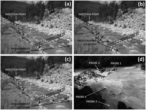
The ECT measurement probes were set up in three arrangements, depending on whether the goal was to measure discharge, to study mixing lengths, or to study the variability of BTCs and discharge measurements with measurement location (Figure ). To assess whether the salt was completely mixed at the downstream end of the reach, two probes were set up on opposite sides of the stream, and staggered downstream by 5 to 10 m. When access to both sides of the stream was not possible, the probes were staggered on the same side of the stream. Complete tracer mixing in the stream channel was assumed if the two measurements agreed within a reasonable tolerance, based on measurement uncertainty.
Figure 2. Examples of experimental setups at (a, b, c) Rutherford Creek and (d) Pemberton Creek. For reference for Rutherford Creek, the distance from the injection point to the location where complete mixing was verified was 140 m and the mean wetted width was 7.7 m. For reference for Pemberton Creek, the mean wetted width was 10.0 m.
To study mixing lengths, complete mixing was first verified by comparing discharges determined from two probes placed as described earlier. These first two probes were typically located at least 25 wetted widths downstream, the recommended minimum reach length from Day (Citation1977). Additional probes were installed at a range of distances between the location of the first two probes and the injection point.
To study variability associated with measurement location, complete mixing was first verified by comparing discharges determined from two probes placed as described earlier. In subsequent measurements, probes were placed downstream of the point of complete mixing in different areas of the stream. Figure d shows an example probe setup for measurement location variability, where probes were placed in a slow-moving side pool (Probe 3), in a backwater eddy behind an obstruction (Probe 2), in a flow constriction (Probe 1) or in turbulent whitewater (Probe 4). In some scenarios, the probes were placed in close proximity to minimize the effects of longitudinal dispersion of the tracer as much as possible. In other scenarios, some probes were placed significantly farther downstream (up to 54 wetted widths) to observe the effects of extending the reach length.
Channels were surveyed to determine reach length, reach gradient, average wetted channel width and a classification of channel morphology. Reach length was measured with a surveyor’s tape or a LTI TruPulse 360R rangefinder (specified accuracy from manufacturer for distance measurements is ± 30 cm). Reach gradient was calculated using reach length measurements and vertical distance measurements with the rangefinder. Average wetted channel width was measured with a surveyor’s tape when the stream was small enough to wade across safely; otherwise, a rangefinder was used. Width measurements were taken at three to five locations along the stream reach and averaged. Distances were measured to the nearest 0.1 m. Channel morphologies were determined by visual observation in the field and from photographs. These observations were matched to specific morphologies detailed in the BC Channel Assessment Procedure Guidebook (Citation1996). The morphologies in Table refer to the classifications in the Field Guidebook.
Uncertainty analysis
The uncertainty in stream discharge determined from dilution gauging has three sources: the mass (or volume) or salt (solution) injected, the area under the BTC, and the calibration factor. The total uncertainty in a discharge measurement can be expressed either in terms of a maximum probable error (usually at a 95% confidence level) or a maximum possible error; the latter was used here. For injection of dry salt, the maximum possible fractional error (δdm) was calculated as(4)
where is the uncertainty in the mass of salt injected into the stream, δA is the uncertainty in the area under the BTC, and δCFT is the uncertainty in the value of CFT. Analogous expressions hold for injection of salt in solution.
If the salt was weighed before injection, the uncertainty of mass injected was assigned the resolution of the mass scale (typically 0.1 g). For some injections, unweighed boxes with nominal salt masses (1.0 or 1.8 kg) were injected. In that case, multiple boxes of salt were weighed, and the uncertainty was taken as two times the standard deviation of the measured mass.
The uncertainty associated with the area under the BTC was determined as(5)
where n is the number of ECT measurements during the passage of the salt wave and σ represents the stability of the ECT reading. If the recorded ECT was completely stable, then σ was assigned the resolution of the probe (typically 0.01, 0.1 or 1 μS/cm, depending on the equipment and range of ECT values); otherwise, σ was estimated as the uncertainty in background ECT values observed at the stream site (e.g. if the measurement probe recorded background ECT values between 20.0 μS/cm and 20.4 μS/cm, then σ was set equal to ± 0.2 μS/cm). Each measurement point has two sources of uncertainty: the measurement itself and the background ECT subtracted from the measurement – thus the multiplication by 2.
The uncertainty in CFT was based on the variability of the CFT values measured in a related study by the author (Richardson Citation2015). Two different values of were used in this study, depending on how the calibration procedure was performed. If the calibration was performed by the author, then the value of
was based on the repeatability of the calibration (i.e. how much the CFT varied between calibrations using the same stream water and same environmental conditions). Therefore, it was taken as two times the standard deviation of seven calibrations on the same stream water performed by the author in a controlled laboratory setting. The specific value used was
= 0.003 L·cm·μS−1·m−3. If the calibration was not performed and the CFT was estimated, then the value of
was assigned a value of two times the standard error of the residuals of the relation between CFT and ECBG (
= 0.010 L·cm·μS−1·m−3) found by the senior author (Richardson Citation2015).
Mixing length determination
The maximum possible error was used as the tolerance range for each measurement. If the discharge measured at an upstream point agreed with the farthest downstream discharge measurement, within the tolerance range, then it was deemed that complete mixing had occurred at the location of the upstream probe for that measurement.
Measurement location and discharge variability
Five streams were studied specifically for discharge variability in relation to probe location. A measure of the uncertainty related to probe location, , was computed as follows:
(6)
where Qmax and Qmin are the maximum and minimum discharges among probes, respectively. Some probes were placed in areas of significant upstream flow in a side pool (Carnation Creek Trib C), in areas of turbulent whitewater (Mosquito Creek), in near-stagnant pools behind boulders (Pemberton Creek) or in fast-flowing narrow chutes of water (Pemberton Creek).
Relations for dosing guidelines
To develop dosing guidelines, one approach is to derive a relation between the mass of tracer injected and the difference between peak and background tracer concentrations during passage of the BTC. The first step in deriving the relation is to represent the area under the BTC in non-dimensional form as(7)
where ϕ is the normalized difference between ECT and ECBG, computed as(8)
and Δτ is one time step of a non-dimensional time, τ, computed as(9)
where th (s) is the harmonic mean travel time of the tracer pulse. Combining Equations Equation(1)(1) and (7) and re-arranging yields the following relation:
(10)
Since th is equal to the reach length, L (m), divided by the mean velocity, (m/s), and Q divided by
is equal to the mean cross-sectional area of the stream channel, AC, Equation Equation(10)
(10) becomes
(11)
The relation in Equation Equation(11)(11) indicates that the appropriate mass of salt to inject can be estimated given estimates or measurements of L, AC, CFT and A*, and a desired change in ECT from background to peak is specified. The derived relation in Equation Equation(11)
(11) is algebraically equivalent to the Rhodamine WT dosage suggestion reported by Kilpatrick (Citation1970), which relates the volumetric Rhodamine WT dosage to the desired peak Rhodamine WT concentration.
To determine A*, each BTC must be transformed into non-dimensional form. For this study, 121 discharge measurements from the field studies and 54 discharge measurements from fieldwork performed by Northwest Hydraulic Consultants Ltd. (NHC) were analyzed. The distribution of values of A* was used to determine recommended values for use in salt dosing calculations.
Results
Mixing characteristics
The mixing lengths summarized in Table range from 6.5 to 24 wetted widths based on opposite-side agreement and 2.4 to 25 wetted widths based on agreement of same-side probes. However, the validity of same-side agreement is contradicted by results from Bridge Glacier Creek West and Rutherford Creek reach 1. At Bridge Glacier Creek West, there was a lack of a clear relation between discharge and stage (Spearman’s ρ = 0.05, p = 0.45, for one-tailed test for positive rank correlation), which suggests that the tracer was not sufficiently mixed at the measurement location to yield accurate discharge measurements. For Rutherford Creek reach 1, there was a lack of agreement between two probes that were placed on opposite sides of the stream, indicating that the mixing length was at least as long as the distance between the injection point and the measurement probes.
Table 3. Mixing lengths determined from discharge measurements at multiple locations. “Mixing length assumed from same-side probes” indicates that two measurement probes on the same side of the stream measured similar discharges, while “mixing length assumed from opposite-side probes” indicates that two measurement probes on opposite sides of the stream measured similar discharges. “NA” indicates that there were probes on only one side of the stream. Note that some streams have different mixing lengths based on discharge.
Table summarizes results from a reach-length case study of Carnation Creek Trib C. In all six trials, the calculated discharge steadily increased as a function of reach length, particularly downstream of probe 4. The relative increase in discharge decreased with increasing flow levels.
Table 4. Discharge measurements (m3·s−1) for Carnation Creek Trib C. Reach length (m) for each probe is in parentheses. From visual field observation, the wetted width was between 1.5 m and 2.0 m for Injections 1 through 5, and unknown for Injection 6.
Measurement location and discharge variability
The shape of the BTC varied substantially among probe locations within a channel (Figure ). However, despite the differences in BTCs, most measured discharges were in reasonable agreement for each injection ( < ± 10%; Table ).
Figure 3. Breakthrough curves (BTCs) for discharge measurements focused on measurement location variability. One sample injection for each stream. Different plotting symbols are the BTCs for different probes for the same injection: (a) Carnation Creek Trib C Injection 3 (Q = 0.040 m3·s−1 ± 4.4%; (b) Carnation Creek Trib L Injection 2 (Q = 0.0090 m3·s−1 ± 4.3%; (c) Mosquito Creek Injection 1 (Q = 0.349 m3·s−1 ± 2.9%; (d) Pemberton Creek Injection 5 (Q = 2.14 m3·s−1 ± 2.7%. EC – electrical conductivity.
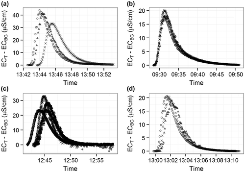
Table 5. Discharge measurements for injections focusing on measurement location variability. The value of  is a measure of the percent error in measured discharge for one injection.
Relations between A* and reach characteristics
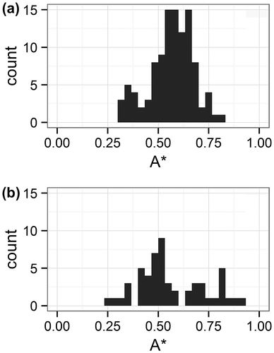
Values of A* from all streams (field study streams and NHC streams) ranged from 0.25 to 0.93, with a mean of 0.55 (Figures and ). The average A* values are similar for the field study streams and NHC streams. The spread of A* values is less for the field study streams compared to the NHC streams (Figure ). The spread of A* values decreases when looking at specific streams. Carnation Creek Trib L had high A* values relative to all other streams. Based on the non-dimensional BTCs (Figure ), there are two observed trends: (1) the tails of the non-dimensional BTCs were longer (or “shallower”) for larger A* values; and (2) the non-dimensional first arrival times (τo) were earlier for larger A* values.
Figure 4. Plots of all non-dimensional breakthrough curves (BTCs): (a) BTCs with A* values between 0.24 and 0.49 (n = 51), (b) BTCs with A* values between 0.49 and 0.62 (n = 67), and (c) BTCs with A* values between 0.62 and 0.94 (n = 51).
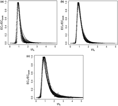
Figure 5. Boxplot of A* values for all injections from all streams (field study streams and Northwest Hydraulic Consultants Ltd. streams). EC – electrical conductivity.
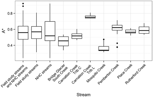
Figure 6. Histograms of A* values: (a) Field study streams (n = 121); (b) Northwest Hydraulic Consultants Ltd. (NHC) streams (n = 54).
When looking at all streams, there is a significant (p < 0.001) positive trend between A* and discharge (Figure ), and a significant (p < 0.001) negative trend between A* and reach length (Figure ). The Pemberton Creek measurements for a long reach length (xm = 53·w, seen as outlier dots in Figure ) had much lower A* values compared to the other Pemberton Creek measurements.
Figure 7. Variability of A* with discharge, for all injections from all field study streams (n = 121). The black line is a linear regression fit to provide visual reference (p < 0.001, adjusted R2 = 0.16).
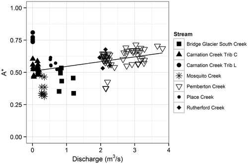
Figure 8. Variability of A* with ratio of reach length to wetted width, for all injections from all field study streams (n = 121). The black line is a linear regression fit to provide visual reference (p < 0.001, adjusted R2 = 0.30).
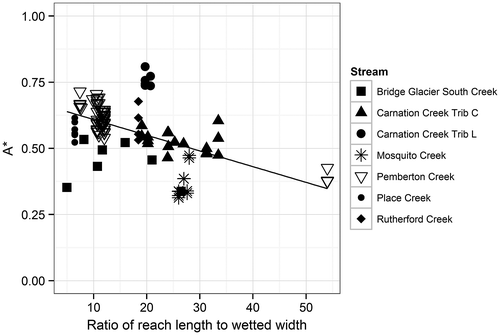
A series of measurements at Pemberton Creek were taken for a wide range of discharges at a constant reach length (Figure ). The relation between A* and discharge was not quite significant (p = 0.053). A series of measurements at Carnation Creek Trib C were taken at different reach lengths for a constant discharge (Figure ). Despite the small spread in A* values, there is a significant negative relation between A* and reach length (p < 0.001). This negative relation was also observed at Pemberton Creek, as the long reach measurements had much lower A* values compared to the shorter reach measurements (Figure ).
Figure 9. Variability of A* with discharge, for a constant reach length, at Pemberton Creek. The relation was weak and not quite significant (p = 0.053).
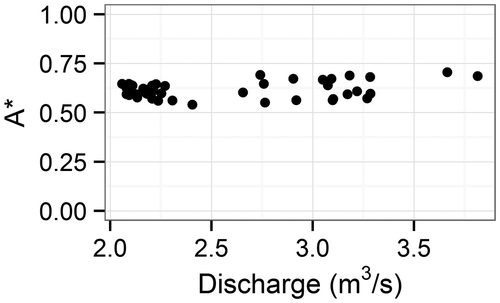
Figure 10. Variability of A* with reach length, for constant discharge, at Carnation Creek Trib C. The black line is linear regression relation for all injections (p < 0.001).
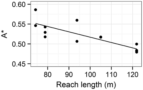
Table shows variability of A* based on measurement location. Carnation Creek Trib L had similar A* values for all three probes, and the stream was significantly narrower than the other streams (wetted width = 1 m). The highest and lowest A* values occurred in all areas of the stream (e.g. slow side-pool, main water column), indicating that there is no systematic relation between A* value and measurement location across different streams. However, for each stream, the highest and lowest values of A* occurred at the same measurement location for all injections.
Table 6. Measurement location variability of A*. Highest/lowest A* is the highest/lowest average A* value from one probe for all injections at that stream. In the location description, the value in brackets is a visual estimate of the ratio of the local velocity near the probe to the maximum local velocity across the channel.
Discussion
Mixing characteristics
With the exception of Bridge South Creek Reach 2, the mixing lengths in this study, ranging between 6.5 and 24.5·w, support a refinement of Day’s (Citation1977) recommendation. Rather than applying a fixed rule of 25 wetted widths for the mixing length, it is apparent that mixing lengths are reach-dependent, as expected, and that shorter mixing lengths can be appropriate in some reaches. Although the value of xm = 2.4·w for Bridge South Creek Reach 2 is surprising, the measured discharges were generally consistent with those measured at other reaches on that stream, and it may be the case that the characteristics of that stream enhanced rapid mixing. The injection point for Bridge South Creek Reach 2 was at a flow constriction between two large boulders (wetted width at injection point was approximately 2 m), which facilitated rapid mixing.
An important finding is that it can be problematic to use two probes on the same side of the stream to confirm adequate mixing. The trials at Rutherford Creek Reach 1 had same-side probe agreement, but disagreement in the opposite-side probe measurement. Two probes on the same side as the injection location yielded a discharge of 2.60 ± 0.05 m3·s−1, while one probe on the opposite side of the injection location yielded a discharge of 20.9 m3·s−1. This extreme discrepancy was seen during all injections, and all probes were approximately the same distance downstream of the injection point (xm = 104 ± 1 m). Using only the same-side probes, this measurement would be taken as adequate, when it is obvious that complete mixing had not occurred across the entire stream channel. Another example of this “same-side error” was seen at Bridge Glacier West Creek. The discharges yielded from the four probes were in reasonable agreement, but there was no clear relation between stage and discharge despite the channel remaining stable, indicating that the measurements were not accurate, likely due to incomplete mixing across the stream channel. The same-side error suggests that at least one opposite-side probe is necessary to confirm adequate mixing and to determine mixing lengths with confidence. Day (Citation1977) did not specify whether he placed probes on both sides of the stream or on only one side of the stream.
It was observed at Carnation Creek Trib C that determining adequate mixing length and verifying discharge measurements can be confounded by stream-subsurface water fluxes. A steadily increasing discharge with increasing reach length indicates that the stream was gaining water through the reach, diluting the tracer and causing a higher discharge measurement downstream (Table ). This phenomenon has been reported by others (e.g. Zellweger et al. Citation1989; Clow and Fleming Citation2008). The bottom portion of Trib C (location of Probe 4 and farther downstream) flows across the floodplain of the main stem of Carnation Creek. Groundwater could be discharging into Trib C from Carnation Creek’s floodplain aquifer. In addition, some of the injections were performed during a rain event, and surface and/or shallow subsurface runoff likely entered the stream throughout the measurement reach. Clow and Fleming (Citation2008) used constant-rate injection to confirm complete mixing, and found a steady increase in discharge moving downstream. However, they could not distinguish whether it was due to surface-subsurface water fluxes or Rhodamine WT decay, which can also be problematic (Runkel Citation2015).
Losing and gaining reaches will affect the discharge measurement differently. If the stream is losing water downstream of complete mixing, it would lose equal amounts of water and tracer, with no effect on the measured discharge. However, losses of water from the stream, prior to complete mixing, would affect the measurement. Therefore, a losing reach would accumulate measurement error only in the mixing reach, while a gaining reach would accumulate measurement error throughout the entire measurement reach (mixing reach and downstream of the mixing reach). In both cases, it is best to measure the discharge at the minimum xm that guarantees complete mixing to minimize the effects of lateral water fluxes (both groundwater recharge and discharge).
In contrast to Trib C, a long reach length was not an issue at Pemberton Creek. Measurements at lengths xm = 12·w and xw = 54·w agreed. Lateral channel inputs of water were likely less significant at this stream due to the following: (1) the weather was dry at the time; (2) Pemberton Creek is a glacier-fed stream, and receives most of its water from a point source upstream, especially during dry conditions; (3) Pemberton Creek is a steeper, valley-incised stream, and is likely not influenced by the near vicinity of other streams; (4) the drainage area for Pemberton Creek is significantly larger than the drainage area for Trib L, and therefore the effect of lateral water fluxes per unit of stream length will be smaller in comparison to the total flow.
Based on the preceding reach-length discussion, the same measurement reach should be used (i.e. the same injection point and measurement point for all injections) when comparing discharges over time (e.g. generating a rating curve). However, stream-subsurface water fluxes and adequate mixing length will vary with discharge, so using the same measurement reach may not completely resolve these issues.
The potential issues associated with “same-side” measurement error and stream-subsurface water fluxes may be impossible to reconcile in some situations, but being aware and knowledgeable of them will aid in attributing uncertainty levels and confidence to discharge measurements.
Measurement location and discharge variability
The uncertainty in Q for many of the trials in Table was larger than 5%. It is common to attribute a measurement discrepancy between probes to inadequate mixing (i.e. xm is too short), but this study shows that the discrepancy can also be due to measurement location even if the mixing length is adequate.
There was no discernible relation between measurement location and discharge (e.g. not all probes in fast-flowing water had closer measurement agreement than probes in slow-flowing pools). Probes that were located in fast-moving chutes of water generally had the smoothest BTCs (e.g. in Figure : Carnation Creek Trib C, BTC represented by “X” symbols; Mosquito Creek, BTC with the earliest first arrival time). Smooth BTCs are preferred because they indicate that the tracer is arriving at the measurement location in a continuous flow of tracer material. However, a smooth BTC does not confirm that the tracer is well mixed throughout the stream channel. For example, smooth BTCs were observed for trials at Pemberton Creek and Place Creek from measurement locations that had inadequate mixing.
Abrupt changes in ECT indicate that the tracer is arriving in discontinuous “pockets” of tracer material, which is not reflective of a well-mixed water column. The BTC represented by triangle symbols in Figure for Pemberton Creek is an example of a choppy BTC that exhibits abrupt changes in ECT readings. The probes that recorded choppy BTCs were generally located in areas of slow moving water (side-pools, behind obstructions). The choppiness also suggests that the stream reach is not long enough to allow for adequate mixing. In the case of Pemberton Creek, both the choppy BTC (triangle symbols) probe and another, smoother BTC (“X” symbols) probe were in slow side-pools, but the choppy BTC probe was on the opposite side of injection. Although the measurements agreed well in this case, the tracer was likely not completely well mixed across the entire stream channel. BTC choppiness may also be due to probe placement in areas of aerated water, as air bubbles will cause a downward spike in ECT reading (e.g. in Figure : Mosquito Creek, BTC represented by circle symbols). Moore (Citation2005) observed choppy BTCs in areas with groundwater discharge through the bed. Finally, a choppy BTC can also occur if the probe is located near the flow detachment zone associated with an upstream structure. The eddy line behind the structure will move back and forth across the stream and a probe located at a fixed location within the zone where this eddy line is located will alternately measure the faster water associated with the main flow and the water in the eddy behind the obstruction.
Based on these results, we recommend that probes should be placed in areas of fast-flowing, non-aerated water upstream of or adjacent to obstructions whenever possible. For determining discharge, variations in BTCs associated with measurement location may lower the precision of the measurement, even at a location downstream of complete mixing. Furthermore, the effect of measurement location on the shape of the BTC may confound other studies that use BTC shape to quantify residence times of solutes and transient storage parameters (e.g. Szeftel, (Dan) Moore, and Weiler Citation2011; Jiménez and Wohl Citation2013; González-Pinzón, Haggerty, and Dentz Citation2013). Studies using tracer dilution should provide a photograph and detailed description of measurement location in relation to area of the channel (e.g. same/opposite side of injection, behind an obstruction), reach length, reach width and a qualitative assessment of the flow conditions at the probe location (e.g. in a back-eddy, or in aerated fast-flowing water).
Relations between A* and reach characteristics
Three physical processes affect the BTC shape: advection, longitudinal dispersion and transient storage. A stream dominated by advection with minimal longitudinal dispersion and transient storage would cause the tracer to quickly flush through the measurement reach, resulting in a short-duration BTC and a short BTC tail. A short BTC tail compared to a long BTC tail would correspond to a relatively smaller harmonic mean travel time (th), and the transformation by th will “compress” the non-dimensional BTC less, resulting in a later time of first tracer arrival. Conversely, a stream with significant transient storage would result in a long-duration BTC and a long BTC tail, which would correspond to a larger th, and the non-dimensional BTC will be more compressed, resulting in an earlier τo. A long tail will remain long after transformation, leading to more area under the non-dimensional BTC (A*) when compared to a short-tailed BTC.
The high A* values for Carnation Creek Trib L were due to the long tails of the BTCs for this stream, indicating a large amount of transient storage and/or longitudinal dispersion throughout the measurement reach. Most tracer pulses from other streams were around 10 min long, while the pulses at Trib L lasted 20 min. At Trib L, the reach contained multiple pools connected by small trickles of water, with a high bed roughness relative to the size of the wetted channel, resulting in substantial transient storage. The mean water velocity ( = 0.07 m·s−1) and discharge (Q = 0.009 m3·s−1) measured at Trib L were lower than at any other stream studied. Similar velocities (
= 0.10 to 0.23 m·s−1) and discharges (Q = 0.010 m3·s−1 to 0.040 m3·s−1) were also measured at Carnation Creek Trib C for a series of injections during a rain event.
Transient storage may change with discharge depending on the stream. For example, for four injections at Carnation Creek Trib C, A* decreased with increasing discharge. The active stream channel visibly changed from a string of pools connected by small trickles of water at low flow, to a faster, uniform flow of water at higher flows. On the other hand, it is also possible that in some streams a higher discharge will activate new areas along the channel’s edge that will pool with water, resulting in more transient storage and a higher A*. Pemberton Creek was the only stream studied with a large range of discharges measured for a constant reach length (Figure ). The lack of relation between A* and discharge suggests that the impact of transient storage remained constant at this stream.
As shown in Figures and , A* tends to decrease as the reach length is extended. This relation is most apparent for the long reach length trials at Pemberton Creek. For these three measurements, the peak ECT at the downstream location was half the value at the upstream location, and th at the downstream location was four times the value at the upstream location, resulting in the value of A* at the downstream location equal to half the value at the upstream location. Since the peak ECT and th do not scale proportionally as the measurement location is moved downstream, A* will vary with reach length.
Measurement location can have a large effect on A*. For example, A* values from Mosquito Creek ranged from 0.32 to 0.46, even though all five probes were within 8 m of each other (for a measurement reach of 140 m). For a narrow stream (e.g. Trib L), measurement location had less effect on A*.
The distribution of A* values for the NHC data set is comparable to those for the field study. For measurements at markedly higher flow levels (Q = 20, 34 and 40 m3·s−1), the resulting A* values (0.41, 0.47, 0.58, 0.48, 0.53) were close to the average A* value (0.55), suggesting that typical values of A* remain similar at higher discharges.
Using A* for dosage guidelines
It is proposed that the average A* value (0.55) can be used to generate a first-order estimate of the amount of salt to inject into a stream using Equation Equation(11)(11) . The remaining variables in the equation would be estimated or calculated (Ac, CFT and L) or specified by the practitioner (the desired peak ECT over background ECT). The cross-sectional area of the channel could, as a first approximation, be estimated as the product of the mean wetted width and mean depth. Table shows an example salt dosage calculation.
Table 7. Example salt dosage calculation using A* and Equation (11).
The uncertainty of the salt dose will be based on the uncertainty of A*, which may be taken as two times the standard deviation of all computed A* values (0.13). The uncertainty of A* (± 0.26) is approximately half (50%) the mean value of A* (0.55). The A* uncertainty suggests that the estimate of the salt dose may be incorrect by up to 50% for a 95% confidence level. If the stream is under-dosed by 50%, then the peak ECT over background ECT will be half of the desired value. For example, if the resulting peak ECT over background ECT is 15 µS·cm−1 instead of 30 µS·cm−1, the discharge may still be computed, but with a higher uncertainty. If the stream is overdosed by 50%, the peak ECT over background ECT will be 150% of the desired value, which will decrease the uncertainty associated with the computed discharge. Compared to the wide range of dosage guidelines suggested by others (Table ), a 50% uncertainty in dose is reasonable. However, the dose uncertainty will also depend on the uncertainty in estimating other parameters in Equation Equation(11)(11) , such as the mean depth and wetted width.
Conclusions
Apart from one outlier, the minimum adequate mixing length was found to lie between 6.5 and 24.5 wetted widths for the study reaches. Recognition that required mixing lengths vary among stream reaches is a refinement of Day’s (Citation1977) recommendation that mixing lengths be at least 25 wetted widths. Placing probes on opposite sides of the stream is required to verify with confidence that adequate mixing has occurred, as probes on the same side of the stream may yield similar discharges even if the tracer is not well mixed across the stream channel. If placement on both sides of the stream is not possible, then the measurement reach length should initially be at least 25 wetted widths downstream of the injection point to ensure the tracer is fully mixed across the stream channel at the measurement location. If the stream has poor lateral mixing and is not suitable for salt dilution gauging, no length of mixing reach will produce an accurate result.
Surface and subsurface discharge into the channel can confound the determination of xm and result in ambiguous discharge measurements, as seen in this study and reported by others (Zellweger et al. Citation1989; Clow and Fleming Citation2008), and is especially problematic if same-side probes are used to assess the adequacy of lateral mixing. Therefore, the shortest possible mixing reach should be used to minimize effects of lateral water inputs. Lateral water fluxes will likely be a greater issue for smaller streams since they will have a larger relative impact on the total flow. One could take point measurements of ECBG along the stream reach to help diagnose the existence of significant lateral inputs, since varying values of ECBG suggests inflow from a different water source (Moore et al. Citation2008).
Probe location can significantly affect the discharge measurement, even downstream of adequate mixing. Differences in derived discharge were as high as 9% between different probe locations for the same measurement, which may be higher than the calculated uncertainty for a discharge measurement. Therefore, depending on probe placement, the actual uncertainty in a discharge measurement may be higher than that calculated using standard approaches.
Generally, it is best to be consistent in measurement location for any one reach and place the probes upstream of obstructions that produce large recirculation zones downstream. Aerated areas and side pools tend to produce choppy BTCs, which indicate that the tracer is arriving in pockets and may indicate inadequate mixing. Probes in fast-moving chutes of water resulted in the smoothest BTCs, which suggests (but does not confirm) that the tracer is well mixed across the channel. Therefore, it is advised to place probes in fast-moving (non-aerated) water when possible. The practitioner should provide detailed descriptions and photographs of the measurement locations to assist in documenting factors that influence the accuracy of a measurement.
Tracer dosage can be estimated based on estimates of channel geometry, desired peak tracer concentration over background tracer concentration, and the non-dimensional area under the BTC, A*. Analyzing 165 BTCs, a first-order estimate of A* was found to be equal to 0.55, with a standard deviation equal to 0.13. Using two times the standard deviation as a measure of A* uncertainty, the uncertainty is approximately ± 50%, suggesting that using this dosage approach may result in under- or over-dosing the stream by up to 50%.
The variability of A* decreased when focusing on a specific stream reach. The value of A* also seems to be dependent on reach length, the amount of in-stream storage in the stream reach and measurement location. Therefore, it may be possible to generate more accurate estimates of A* for dosing estimates based on previous injections from a stream reach or one with similar morphology.
Funding
This work was supported by Natural Sciences and Engineering Research Council of Canada, grant number [Discovery Grant – Dr. Dan Moore]; Co-funded: (1) Mitacs and (2) Northwest Hydraulic Consultants Ltd., grant number [Mitacs Accelerate Internship – Mark E. Richardson].
Acknowledgements
Funding for this project was provided by the Natural Sciences and Engineering Research Council of Canada by a Discovery Grant held by RDM, and by Northwest Hydraulic Consultants Ltd. and Mitacs as part of a Mitacs Accelerate Internship held by the senior author. We thank Aquarius Research & Development Inc., Hoskin Scientific, Ministry of Environment, Northwest Hydraulic Consultants Ltd. and Water Survey of Canada for the use of their field equipment. We also thank numerous graduate students in the University of British Columbia Department of Geography, Brett Eaton, Luke Gould, Greg Grzybowski, Eleri Harris, Michele Koppes, Alexis Moyer and Robin Pike, for field assistance.
References
- BC Channel Assessment Procedure Guidebook. 1996. Forest practices code of British Columbia act operational planning regulation. Victoria, BC. https://www.for.gov.bc.ca/tasb/legsregs/fpc/fpcguide/channel/chan-toc.htm.
- Clow, D. W., and A. C. Fleming. 2008. Tracer gauge: An automated dye dilution gauging system for ice-affected streams. Water Resources Research 44 (12): W12441, 11 pp.
- Comiti, F., L. Mao, A. Wilcox, E. E. Wohl, and M. A. Lenzi. 2007. Field-derived relationships for flow velocity and resistance in high-gradient streams. Journal of Hydrology 340 (1-2): 48–62. 10.1016/j.jhydrol.2007.03.021
- Day, T. J. 1977. Observed mixing lengths in mountain streams. Journal of Hydrology 35 (1-2): 125–136. 10.1016/0022-1694(77)90081-6
- Fischer, H. B. 1966. Longitudinal dispersion in laboratory and natural channels. Technical Report KH-R-12, 250 pp. Pasadena, California: California Institute of Technology.
- Glover, R. 1964. Dispersion of dissolved or suspended materials in flowing streams. Professional Paper 433B. Washington, DC: United States Geological Survey, 32 pp.
- Gomi, T., R. C. Sidle, and J. S. Richardson. 2002. Understanding processes and downstream linkages of headwater systems. BioScience 52 (10): 905–916. 10.1641/0006-3568(2002)052[0905:UPADLO]2.0.CO;2
- González-Pinzón, R., R. Haggerty, and M. Dentz. 2013. Scaling and predicting solute transport processes in streams. Water Resources Research 49 (7): 4071–4088. 10.1002/wrcr.20280
- Hamilton, A. S., and R. D. Moore. 2012. Quantifying uncertainty in streamflow records. Canadian Water Resources Journal 37 (1): 3–21.
- Herschy, R. 1975. The accuracy of existing and new methods of river gauging, 485 pp. Reading, UK: University of Reading.
- Hudson, R. and J. Fraser. 2002. Alternative methods of flow rating in small coastal streams. Forest research extension note EN-014, 11. Nanaimo, BC: British Columbia Forest Service, Vancouver Forest Region. 11 pp.
- Hudson, R., and J. Fraser. 2005. Introduction to salt dilution gauging for streamflow measurement part 4: The mass balance (or dry injection) method. Streamline Watershed Management Bulletin 9 (1): 6–12.
- Jiménez, M. A., and E. Wohl. 2013. Solute transport modeling using morphological parameters of step-pool reaches. Water Resources Research 49 (3): 1345–1359. 10.1002/wrcr.20102
- Kelleher, C., T. Wagener, B. McGlynn, A. S. Ward, M. N. Gooseff, and R. A. Payn. 2013. Identifiability of transient storage model parameters along a mountain stream. Water Resources Research 49 (9): 5290–5306. 10.1002/wrcr.20413
- Kerr Wood Leidal Associates, Ltd. 2007. Run-of-River hydroelectric resource assessment for British Columbia. Final report prepared for BC Hydro, Nov. 2007.
- Kilpatrick, F. A. 1970. Dosage requirements for slug injections of Rhodamine BA and WT dyes. In Geological Survey Research, 1970, Chapter B, Professional Paper 700-B, 250–253. Washington, D.C.: United States Geological Survey, 265 pp.
- Kite, G. 1993. Computerized streamflow measurement using slug injection. Hydrological Processes 7 (2): 227–233. 10.1002/(ISSN)1099-1085
- Lee, A. J., and R. I. Ferguson. 2002. Velocity and flow resistance in step-pool streams. Geomorphology 46 (1-2): 59–71. 10.1016/S0169-555X(02)00054-5
- Liu, Y., J. Freer, K. Beven, and P. Matgen. 2009. Towards a limits of acceptability approach to the calibration of hydrological models: Extending observation error. Journal of Hydrology 367 (1-2): 93–103. 10.1016/j.jhydrol.2009.01.016
- McMillan, H., T. Krueger, and J. Freer. 2012. Benchmarking observational uncertainties for hydrology: Rainfall, river discharge and water quality. Hydrological Processes 26: 4078–4111. 10.1002/hyp.v26.26
- Moore, R. D. 2004. Introduction to salt dilution gauging for streamflow measurement: Part 1. Streamline Watershed Management Bulletin 7 (4): 20–23.
- Moore, R. D. 2005. Introduction to salt dilution gauging for streamflow measurement part 3: Slug injection using salt in solution. Streamline Watershed Management Bulletin 8 (2): 1–6.
- Moore, R. D., G. Richards, and A. Story. 2008. Electrical conductivity as an indicator of water chemistry and hydrologic process. Streamline Watershed Management Bulletin 11 (2): 1–6.
- Oberg, K., and D. S. Mueller. 2007. Validation of streamflow measurements made with acoustic Doppler current profilers. Journal of Hydraulic Engineering 133 (12): 1421–1432. 10.1061/(ASCE)0733-9429(2007)133:12(1421)
- Pelletier, P. M. 1988. Uncertainties in the single determination of river discharge: A literature review. Canadian Journal of Civil Engineering 15 (5): 834–850. 10.1139/l88-109
- Richardson, M. 2015. Refinement of tracer dilution methods for discharge measurements in steep mountain streams. Unpublished M.Sc. thesis, The University of British Columbia, Vancouver, Canada.
- Runkel, R. L. 2015. On the use of rhodamine WT for the characterization of stream hydrodynamics and transient storage. Water Resources Research 51 (8): 6125–6142. 10.1002/2015WR017201
- Szeftel, P., R. D. (Dan) Moore, and M. Weiler. 2011. Influence of distributed flow losses and gains on the estimation of transient storage parameters from stream tracer experiments. Journal of Hydrology 396 (3-4): 277–291. 10.1016/j.jhydrol.2010.11.018
- Waldon, M. G. 2004. Estimation of average stream velocity. Journal of Hydraulic Engineering 130 (11): 1119–1122. 10.1061/(ASCE)0733-9429(2004)130:11(1119)
- Ward, P. R. B. 1973. Prediction of mixing lengths for river flow gaging. ASCE Journal of the Hydraulics Division 99 (7): 1069–1081.
- Ward, A. S., M. N. Gooseff, T. J. Voltz, M. Fitzgerald, K. Singha, and J. P. Zarnetske. 2013. How does rapidly changing discharge during storm events affect transient storage and channel water balance in a headwater mountain stream? Water Resources Research 49 (9): 5473–5486. 10.1002/wrcr.20434
- Westerberg, I., J. Guerrero, J. Seibert, K. J. Beven, and S. Halldin. 2011. Stage-discharge uncertainty derived with a non-stationary rating curve in the Choluteca River. Honduras. Hydrological Processes 25 (4): 603–613. 10.1002/hyp.7848
- Wood, P. J., and A. P. Dykes. 2002. The use of salt dilution gauging techniques: Ecological considerations and insights. Water Research 36 (12): 3054–3062. 10.1016/S0043-1354(01)00519-X
- Yotsukura, N. and E. D. Cobb. 1972. Transverse diffusion of solutes in natural streams. Professional Paper 582-C. United States Geological Survey, Washington D.C.
- Zellweger, G. W., J. A. Avanzino, and K. E. Bencala. 1989. Comparison of tracer-dilution and current-meter discharge measurements in a small gravel-bed stream, Little Lost Man Creek, California. U.S. Geological Survey Water-Resources Investigations Report 89–4150.
- Zimmermann, A. 2010. Flow resistance in steep streams: An experimental study. Water Resources Research 46 (9): W09536, 18 pp.
