 ?Mathematical formulae have been encoded as MathML and are displayed in this HTML version using MathJax in order to improve their display. Uncheck the box to turn MathJax off. This feature requires Javascript. Click on a formula to zoom.
ABSTRACT
A computer model that calculates the transport yield of a nuclide through an arbitrary SISAK experimental set-up has been developed. The model is intended to be used for two types of calculations connected to chemical studies of the heaviest elements. If the production cross section and the nuclide half-life are known, it can be used to estimate the number of decay events to be expected at the detection site. Consequently, if the number of atoms decaying in the detection cells is known, it can be used to estimate the production cross section or the half-life, provided that one of these properties is known.
Introduction
SISAK[Citation1] is an on-line chemical separation technique based on multi-stage liquid-liquid extraction separations using high-speed centrifuges[Citation2,Citation3] for phase separation. It is used for nuclear spectroscopy studies of nuclides with half-lives down to ~0.8 s, and in the previous decades has been adopted for studying the chemical properties of the transactinide elements.[Citation4–Citation6] In SISAK experiments the radionuclides are continuously transported from the production site of an accelerator or a research reactor to the SISAK equipment by means of a gas-jet system.[Citation7,Citation8] A specially designed degassing centrifuge[Citation1,Citation9] is used to transfer the nuclear reaction products attached to aerosol particle “clusters” from the gas-jet to a liquid phase, and to separate the carrier gas and volatile products from the liquid. The temperature of the solution is usually ~70°C in order to enhance the dissolution of the clusters delivered by the gas-jet, increase the efficiency of the degassing step, and to speed up the solvent extraction kinetics in the subsequent separation steps.
The solution leaving the degasser is fed into a SISAK centrifuge battery, which comprises multiple liquid-liquid extraction steps. The number of steps depends on the desired purity of the final product and the time available for separation, which is usually governed by the half-life of the nuclide under investigation. The solution containing the element of interested/to be studied is pumped from the last solvent extraction step to a measuring cell coupled to the nuclear detection system.
The overall efficiency of the SISAK system is defined as the fraction of the number of atoms registered by the detectors to that produced in the nuclear reaction in the target. The overall efficiency depends on several independent factors such as:
the transport efficiency of the gas-jet system. This efficiency includes the capture of recoils on the aerosol particles (”clusters”) in the target chamber, as well as the transport efficiency through the gas-jet capillary;
all chemical yields (in the dissolution, degassing, extraction, back-extraction and washing steps, as well as sorption onto surfaces in the system);
the detection efficiency; and
decay during transport from the target to the detector.
In nuclear spectroscopic investigations of fission products, the need to know the overall efficiency is of minor importance as the production rates are high enough and the SISAK system has been optimized (e.g. by adjusting flow-rates, number of centrifuges, length of tubing, detection cell size) to yield a sufficiently high counting rates at the detector site. Thus, an accurate determination of efficiencies is usually not carried out. In transactinide research, where the SISAK system will be used for studies of the chemical properties of transactinide elements, it is also desirable to achieve a better knowledge and more precise determination of transactinide production cross-sections or a better determination of half-lives. In order to measure a production cross-section, it is necessary to know how many atoms are lost between production and detection. A half-life measurement can be performed based on the number of detected events, the known losses, and the overall transport time provided the number of atoms initially produced is known (a known cross-section). An accurate overall efficiency determination is therefore essential.
Most efficiencies and chemical yields are accessible through tracer experiments but a correction for losses due to decay during transport requires knowledge of the transport time (hold-up time) from the site of production to the detectors. A decay correction is especially delicate if the half-life of the studied nuclide is in the same range as the transport time or even shorter. Thus, methods are needed to accurately calculate the transport times involved in the SISAK equipment.
A rough estimation of the transport time in the SISAK 3 system can be made assuming defined hold-up volumes in the tubes and centrifuges. Measured flow-rates are then used to calculate a total “hold-up” time. However, this will only be a rough estimation as laminar flow profiles and effects of mixing are not taken into consideration.
The transport times in the SISAK system can be investigated experimentally by a response function, i.e. the break-through curve obtained at the detection site after a narrow pulse as a start signal. Results from MCS (Multi-Channel-Scaling) measurements show that the time response initiated by a reactor pulse (~30 ms FWHM, Mainz TRIGA reactor) is a complex function depending on many parameters, such as flow-rates, number of centrifuges and the length and diameter of tubing, etc. Moreover, the transport times are also affected by the target chamber size and the dimensions of the gas-jet capillary tubing, which are different for each accelerator or reactor facility. Thus, every experiment performed should include a separate investigation in which the transport times for the given experimental set-up are determined, but this is not always possible. For example, in accelerator irradiations, a break-through curve may be difficult to obtain since the activity produced has to be sufficient to generate good measuring statistics in interval times as short as 100 ms. Even more importantly, it would also use expensive beam time.
A first attempt to model the nuclide transport through a SISAK system was made by Aronsson.[Citation10] The SISAK equipment in use at that time, SISAK 1[Citation11], had a long hold-up time and worked with high flow-rates, i.e. turbulent flow was established in all tubing, which made the modeling rather simple. The transport time through the gas-jet system was short in comparison with the transport time through the rest of the system, and thus it could be omitted in the model. Furthermore, due to turbulent flow, the transport time in the tubing could be calculated as the ratio between the tube volume and the flow-rate.
The next attempt was performed by Liljenzin and Skarnemark[Citation12], who modeled the transport through a one-step SISAK set-up intended for studies of 263Sg. The transmission of radionuclides through the degassing unit and the centrifuge was based on experimental break-through curves obtained by injection of a short pulse of 99mTc into the centrifuge feed solution, and Laminar flow was assumed in all tubing.
However, to be able to simulate the transport of a nuclide through a more complicated SISAK set-up, i.e. with several steps and different flow-rates of the solutions passing through the steps, it is necessary to have a model that takes the delay characteristics of the different components into account. A method has therefore been developed in which the transport time (a pulse response function) of an arbitrary SISAK experimental set-up can be modeled.
Technical description of the SISAK equipment
With respect to transport modeling, a typical SISAK setup consists of four primary parts:
the gas-jet target chamber,
the degassing unit, consisting of a static mixer to contact the gaseous phase delivered by the gas-jet system with a liquid phase to dissolve the clusters carrying the radionuclides, and a centrifuge to separate the gas from the liquid,
the centrifuges used for extraction and separation of the liquid phases, and
the tube connecting the gas-jet target chamber to the degassing unit, and tubes connecting the centrifuges to each other and to the detection system.
Below, these parts will be discussed briefly with respect to the most probable flow pattern.
Gas-jet target chamber
Geometrically, the target chamber is a gas-filled volume that is large enough to stop the nuclear reaction products from recoiling out of the target chamber. During operation, the chamber is flushed with helium or nitrogen gas at a pressure of ~0.2 MPa. The gas contains aerosol particles, clusters, usually consisting of potassium chloride. If possible, the chamber is designed so that the recoils are stopped close to the outlet in order to decrease the hold-up volume.
Tubes
The tube from the target chamber to the degassing unit is made of polyethylene or stainless steel and usually of 1.5–2.0 mm inner diameter. The tubes transporting the liquid phases are made of PTFE (polytetrafluoro ethylene) and of 1.56 mm inner diameter. In both types of tubing, the flow is laminar at the flow-rates used. The liquid flowrates are usually 0.5–1.5 ml/s in transactinide experiments, which correspond to Reynolds numbers in the range of 400–1200.
Gas/liquid mixers
The flow from the gas-jet system is mixed with a liquid phase in a static gas/liquid mixer. Currently, two different mixers are in use. At liquid flowrates below ~0.5 ml/s, the most efficient one is a glass tube, in which two glass frits are mounted. These frits cause an intense mixing of the gas and the liquid even at gas flow/liquid flow ratios as high as 40–50. The other, older mixer construction works satisfactorily at liquid flowrates ≥1 ml/s, which corresponds to gas flow/liquid flow ratios in the range 5–20. It consists of a glass tube containing a titanium or PEEK (polyetheretherketone) rod with two narrow spiraling spurs milled in opposite directions. The gas and liquid are intensely mixed in the intersections of these spurs.
The gas and liquid flow rates used in SISAK experiments result in strongly turbulent flow through both mixers.
Degassing centrifuge
A drawing and a detailed technical description of the degassing unit used in the SISAK 3 system can be found in ref.[Citation1] The mixture of gas and liquid leaving the static mixer enters the degassing centrifuge centrally and is accelerated to its rotational speed, usually 20,000–25,000 rpm, within the inlet chamber. After acceleration, the mixture is forced through three narrow holes upwards into a separation volume, which contains three chambers. In each of these chambers, the liquid is forced along the wall and then downwards into the liquid phase collecting chamber. Here it encounters a stationary pump wheel that pumps the liquid up and out of the centrifuge via a throttle valve. The purpose of this valve is to keep a proper pressure balance in the degassing centrifuge so that gas bubbles do not escape through the liquid phase outlet. The gas phase is forced towards the center of the centrifuge, and then discharged via an outlet surrounding the central shaft and then fed into the exhaust system of the laboratory.
Both the flow in the inlet chamber of the centrifuge and the flow from the pump wheel to the outlet of the centrifuge are turbulent.
Liquid-liquid centrifuges
A detailed technical description and a drawing of the H-0.3 centrifuge used in the SISAK 3 system can be found in refs.[Citation1,Citation2] The two liquid phases are mixed in a Y-shaped inlet. The mixture enters the centrifuge centrally and is accelerated to a rotational speed of 15,000–25,000 rpm in the inlet chamber. After acceleration, the mixture is forced into a separation volume which contains four small chambers symmetrically arranged around the axis of rotation and completely isolated from each other. In these separation chambers, the mixture has a zigzag motion imposed by the peripheral partition walls and interspersed baffle ridges. The separated phases are discharged from the light and heavy phase collecting chambers by stationary pump wheels, which are individually designed to provide the appropriate pressure and avoid excessive frothing of the liquids. The outlets are equipped with valves, the purpose of which is to maintain a proper pressure balance in the centrifuge. By adjusting the valves, the liquid – liquid interface can be moved until both outgoing phases are free from entrainments of the opposite phase.
The flow pattern in the centrifuge is rather complicated. It is turbulent after the liquids meet in the Y-shaped inlet and in the inlet chamber. The flow should be laminar in the separation chambers otherwise no phase separation would occur. In the narrow transport lines from the pump wheels to the outlet, the flow is turbulent.
The SIMSISAK modeling program
The modeling program is called SIMSISAK, which is an abbreviation for SIMulated SISAK transport. The program is written in the language C and it consists of two subprograms called FLOW and DECAY. The FLOW subprogram calculates how a narrow activity pulse created in the target chamber is broadened when it passes through a specified SISAK set-up. This broadening is achieved by randomly placing each atom on the radius of the tubes in which a laminar flow occurs. FLOW does not take nuclear decay into account, i.e. without further corrections, the resulting breakthrough curve is valid only for a stable or very long-lived nuclide. The resulting break-through curve should be looked upon as a probability function that gives the probability that an atom will reach the detector after a specified time. These probabilities are valid also for single atoms.
The decay corrections are taken care of by the DECAY subprogram that uses a Monte Carlo technique to calculate if an atom formed in the target survives the transport to the detector cell, and whether it decays in the detector cell or not. The program explanations given below are very brief, but further information about the source codes, functions, and handling instructions can be found in ref.[Citation13]
Flow
The general idea behind the construction of the SIMSISAK program package is to obtain the breakthrough curve from a narrow (“spiked”) input, e.g. a nuclide pulse from a reactor. This is made by describing each of the components in the SISAK system with a mathematical function in the program. These functions are then combined in a proper way to describe the actual experimental setup. A basic idea in the program is to let a given (large) number of atoms pass the system and randomly assign each of them a place in the distribution function of each part of the system, thus numerically adding a number of distribution functions. The random number generator used was taken from Matsumoto and Nishimura.[Citation14] The resulting distribution will show the number of atoms put through the system as a function of time.
The program consists of the following functions that will be explained in more detail below: Target, Pipe, Mixer, Degasser, and Centrifuge.
Target
The hold-up time in the target chamber is simulated by dividing the chamber volume by the gas flux. This approach is very rough, but nevertheless, it gives better results than more elaborate models. It should be emphasized that the hold-up time in a typical target chamber is just a few tenths of a second, and therefore the flow pattern used in the target part of the model does not have a large impact on the total time behavior.
Pipe
Flow is considered to be laminar in the pipes without dispersion, according to Equation 1.
where u is flow velocity at distance r from the center of the tube, p1 – p2 the pressure difference between inlet and outlet, L the length of the pipe and μ is the dynamic viscosity of the fluid. For further information, see refs.[Citation15–Citation17] This gives the solution
where R is the radius of the pipe. The volume flow in a tube, ν, can be expressed as
Equations 2 and 3 yield:
where ν is the volume flow. Thus, knowing the length of the pipe it is possible to calculate how long it will take for an atom to pass the pipe.
The input data to the Pipe function are the length and the radius of the pipe, the flow rate, and the kinematic viscosity. The latter is used to calculate the Reynolds number. If Re > 2300 the program warns the user for a possible turbulent flow, and thus a reduced validity of the model.
Mixer
The mixer with glass frits may be seen as a column with two bottoms. Its time behavior is simulated by simply dividing the volume of the mixing chamber with the volume flow-rate. Both the liquid and the gas flows are taken into account.
The mixer containing the rod with spiral spurs has a strongly turbulent flow and thus the delay time can be modeled by dividing the volume of the spurs with the flow-rate.
Degassing and liquid-liquid centrifuges
The liquid-liquid centrifuges are simulated with two constant volumes, a mixing chamber and a separation chamber. The constant volumes give a delay time for each centrifuge according to Equation 5.
where j denotes either organic or aqueous phase and the inlet delay time is
The mixing chamber is simulated by an ideal tank. Typical for such a tank is that an element fed into it as a concentration pulse will be mixed with the solution in the tank, and then the concentration of the element in the tank will decrease exponentially, i.e. if measured at the exit it will change as
where c(t) is the concentration of the element as a function of time, k is the reciprocal of the residence time in the tank and t the time. The value of k is obtained from experimental fits. It is, however, important to remember that the expressions used in the program have only been validated for flow rates ranging from 0.45 ml/s to 1.5 ml/s.
The input data to the centrifuge function are the volume of the centrifuge, the aqueous flow rate, and the organic flow rate.
The degassing centrifuge is simulated similar to the centrifuges but with some exceptions, the most obvious one being that there is only one phase entering the centrifuge volume. Thus, the influence of the gas input is neglected.
The output of each of the functions described above is the time of one specific atom passing that component. This time is, as explained, based on different distributions used by each function. The atom is randomly assigned a place in this distribution, with account given for the appropriate probability. Thus, in order to produce a breakthrough curve, a large number of atoms have to pass the system, each in its individual time.
Decay
The main function of the DECAY program is to calculate whether a radionuclide with a given half-life will decay while it is present in the detector cell, i.e. not decay before it enters or after it leaves the detector. This is done by randomly assigning an atom a place in the distribution function of the system, as obtained by FLOW or by experiment. Thus, the time needed for the element to pass the system is calculated. If the atom has not decayed when it reaches the detector, the probability that it will decay in the detector is calculated by means of assigning the atom a place in the flow distribution function for the detector, thus obtaining the time needed to pass the detector. If the atom decayed within the detector, one atom is counted. This assumes a 100% efficiency of the detector which is most often the case for these alpha decays. However, the efficiency can be set separately if known. Otherwise it is lost. If the production of the target is known, a confidence interval for the number of detected atoms may be calculated by repeating the procedure described above several times. Naturally also the opposite is possible, i.e. on the basis of the detected number of atoms, the production may be estimated.
The decay program consists of two parts, the first of which uses an exponential decay function to calculate the probability that the observed atom has decayed during the time it took to reach the entrance of the detector. The time to reach the detector is randomly determined from the system flow function as determined by FLOW. Naturally, it is also possible to use an experimentally obtained flow function instead of the simulated one.
The detector is simulated with the Pipe function described above. In this case, the function gives the time it takes for an atom to pass the detector. It is then calculated whether the atom decayed during this time and whether the decay was recorded or not depending on the detector efficiency.
Experimental
Pulse experiments
In order to test the model, a series of test experiments were performed at the Mainz TRIGA reactor, which was operated in the pulse mode. The reactivity chosen for these experiments gave a neutron pulse with an FWHM (Full Width at Half Maximum) of 30 ms. This irradiation creates a correspondingly short pulse of fission products in the target chamber; this pulse is then broadened due to different flow patterns when it passes through the SISAK system.
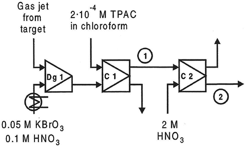
In one of the test experiments, a 239Pu target was used to produce the fission products. The chemical separation system chosen was the one developed for technetium.[Citation18] The separation system is shown schematically in . Briefly, the fission products transported by the gas-jet system are dissolved in 0.1 M HNO3 and 0.05 M KBrO3. In the first solvent extraction step, the aqueous phase is contacted with 2 × 10⁻⁴ M tetraphenylarsonium chloride in chloroform, and technetium, as TcO4− is extracted. The organic phase from the first extraction step was then fed into e.g. a washing step with 0.1 M HNO3 or a strip step with 2 M HNO3 as aqueous phase.
Figure 1. The chemical separation system for Tc. Dg1: degassing unit (including mixer), C1-C2: liquid-liquid centrifuges. 1 and 2 are the positions used for the determination of the experimental breakthrough curves.
At the detection site, the gross γ-activity was measured during 0.1 s intervals using an HPGe-detector. Unfortunately, the available radioactivity did not allow gating on a specific γ-line, and thus gross measurements were the only available alternative. The transport tube from the last centrifuge to the detection site was the same in all experiments. The “detection cell” was a 12.5 cm portion of the tube placed in front of the detector.
Experiments were run with the following SISAK configurations:
gas-jet system and degassing unit,
gas-jet system, degassing unit and an extraction step (cf. ),
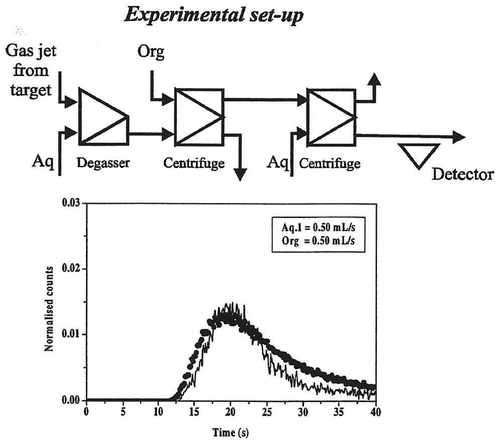
gas-jet system, degassing unit, extraction step and a back-extraction step (cf. ).
Figure 2. Breakthrough curves obtained with degasser and one extraction step for the technetium system. The solid line is the experimentally determined curve and the dots show the curve calculated using the SIMSIAK model.
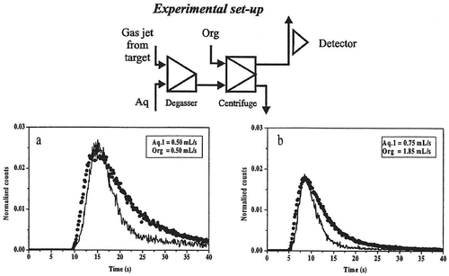
Figure 3. Breakthrough curves obtained with degasser, extraction step and a back-extraction step for the technetium system. The solid line is the experimentally determined curve and the dots show the curve calculated using the SIMSIAK model.
All experiments were run with two different flow-rates, ~0.5 ml/s per phase and ~1 ml/s per phase. These flow-rates were chosen because the majority of the SISAK experiments are run with flow-rates in this range.
The technetium chemistry was chosen because the resultant measured activity mainly stems from two isotopes with similar half-lives. The technetium isotopes with A < 106 have so long half-lives or low fission yields that they do not contribute significantly to the count-rate at the detector site (less than 1% of the detected photons are estimated to originate from these nuclides). Technetium isotopes with A > 108 can also be disregarded because of low yields in the thermal-neutron-induced fission of 239Pu and short half-lives. 106,107,108Tc have half-lives of 35, 21 and 5 s, respectively. Due to the fission yields, the maximum amount of 108Tc (i.e. in the beginning of the pulse) that enters the detector cell is only about 10% of the amount of 106Tc and 107Tc. The amounts of 106Tc and 107Tc are almost equal. Thus, 106Tc and 107Tc are the only nuclides that have to be considered in the comparison of experimental and simulated data.
The SIMSISAK model has also been tested on a much more difficult case, namely the chemical separation system developed for the transactinide element rutherfordium.[Citation4] The chemical separation system is shown in .
Figure 4. The chemical separation system for the Rf and the homologues Zr and Hf. Dg1: degassing unit (including mixer), C1-C3: liquid-liquid centrifuges. Dg2: second degassing unit (“booster centrifuge”). 1, 2, and 3 are the positions used for the determination of the experimental breakthrough curves.
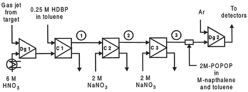
In addition, fission products from thermal-neutron-induced fission of 239Pu were used. Since only fission products were produced, the chemical separation system was used to extract short-lived zirconium isotopes, mainly 98-102Zr. The nuclides transported by the gas-jet system were dissolved in 6 M nitric acid. In the first solvent extraction step, the aqueous phase was contacted with 0.25 M dibutyl phosphoric acid (HDBP) in toluene, and the group 4 and 5 elements were extracted. Then, the organic phase was washed with 2 M sodium nitrate to increase the radiochemical purity.
In this case, experiments were run with the following configurations:
gas-jet system and degassing unit,
gas-jet system, degassing unit and an extraction step (cf. ),
gas-jet system, degassing unit, extraction step and a washing step (cf. ),
gas-jet system, degassing unit, extraction step and two washing steps (cf. ).
Figure 5. Breakthrough curves obtained with degasser and one extraction step for the zirconium system. The solid line is the experimentally determined curve and the dots show the curve calculated using the SIMSIAK model.
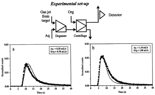
Figure 6. Breakthrough curves obtained with degasser, one extraction step and one washing step for the zirconium system. The solid line is the experimentally determined curve and the dots show the curve calculated using the SIMSIAK model.
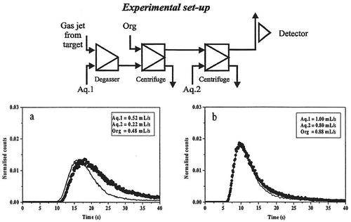
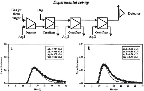
Figure 7. Breakthrough curves obtained with degasser, one extraction step and two washing step for the zirconium system. The solid line is the experimentally determined curve and the dots show the curve calculated using the SIMSIAK model.
The chosen system is complex, with several short-lived zirconium nuclides that decay into short-lived niobium isotopes. To achieve a realistic modeling, it is therefore necessary to correct the experimental points for the growth and decay of the daughter nuclides, and for the co-extraction of daughter nuclides that are formed between the target and the extraction step. The correction was performed using fission yields from Rider[Citation19], and the assumptions that:
- the extraction yields of zirconium and niobium are 95% and 90%, respectively, and that the extraction of molybdenum, as well as the precursors strontium and yttrium, is negligible. These extraction yields have been determined experimentally using the SISAK equipment.
The extraction yields are the same in the extraction step and in the subsequent washing steps (i.e. grown-in molybdenum is washed out in those steps).
The extraction takes place 1.5 s after the formation of the nuclide. This simplification is justified by the fact that the activity pulse, after passing through the gas-jet system and the degassing unit, still is rather narrow. The error introduced by assuming a fixed time of extraction in the decay correction is therefore considered to be negligible.
Results and discussion
– and Citation5–Citation7 show the experimental and modeled break-through curves obtained with degasser and 1, 2 and 3 centrifuges, respectively. Each set-up has been run at two flow-rates that are typical for most SISAK experiments. When performing the modeling, the technetium experiment was used to determine the parameters used to model the mixers, centrifuges, etc. Then, these parameters were used to model the zirconium experiment. This was done to ensure that the parameters used are independent of the studied system, i.e. it does not matter if flow-rates are changed, if the organic phase is the heavy or the light phase or whether the nuclide under investigation is stripped in the second centrifuge or if it stays in the organic phase. As can be seen, there is a good agreement between the experimental data and the calculated curve.
It can also be seen that SIMSISAK predicts the raise of the pulse and the maximum rather accurately. The tail of the pulse is sometimes over-estimated, especially at low flow-rates. The reason is most likely that the model does not take dispersion in the tubes into account. The rough modeling of the target chamber may also cause some problems. However, if using the model to calculate the most probable transport time from the target to the detection site or to calculate the expected number of events, the tail is not as important as the raise and the maximum of the curve.
Another conclusion is that the fitted parameters are not system specific, i.e. they are valid for any SISAK chemical separation system.
As already indicated, one obvious use of the SIMSISAK model is to calculate the transmission of different nuclides through the SISAK equipment, instead of using expensive beam-time to obtain experimental break-through curves. At accelerators, it might be difficult or even impossible to measure break-through curves due to the low activity production, and in this case, the SIMSISAK model will be the only available tool e.g. to optimize the flow-rates to obtain a maximum count-rate at the detection position. As mentioned before the calculated break-through curve is a probability distribution, i.e. the numbers on the vertical axis are a measure of the probability that an atom reaches the detector at a certain time rather than a number of atoms.
In transactinide experiments, the nuclide production rates are extremely low, but nevertheless, the breakthrough curves obtained by SIMSISAK simulations will give information about the most probable arrival time of the nuclides at the detection site. Thus, the model can be used to estimate the number of decay events that can be expected at the detection site, provided that the reaction cross section and the chemical yields are known. The opposite will also be possible, i.e. a measured number of decay events can be used to estimate the reaction cross section, assuming that the chemical yields are known.
At present, the model can be used for SISAK set-ups with any number of centrifuges, and flow-rates ranging from 0.45 ml/s to 1.50 ml/s. Future development work will include tests to validate that the model, with or without modifications, can be used for flow-rates down to ~0.2 ml/s and up to ~3 ml/s. This extended range covers all flow-rate combinations that are possible in SISAK experiments.
Another development will be to include the “booster centrifuge” that is used in transactinide experiments. This centrifuge is a degassing unit that is placed between the last centrifuge step and the detection cells. The input flows to the booster centrifuge are the organic phase containing the element under investigation, an organic phase containing the liquid scintillation chemicals, and an argon flow that will blow away any radon and oxygen (that otherwise would disturb the liquid scintillation measurements) that is present in the solutions. The output flows are an organic phase that is fed into the detection cells, and a gaseous stream that is delivered to the exhaust system. The booster centrifuge also creates the pressure that is necessary to pump the solution through the detection cells. In the model, the booster centrifuge unit can be roughly represented by the model used for the degassing unit. However, to obtain a more accurate model, experiments to characterize the delay properties of the booster unit will be necessary.
It will also be necessary to replace the current tube detection cells with a mathematical model of the meander type cells used in real transactinide experiments.
In future experiments, the SIMSISAK model will be used to optimize the flow-rates to achieve a maximum count-rate of the nuclide under investigation. Until now, this optimization has been done by applying different rules-of-thumb known by experience. The SIMSISAK model will allow a more accurate optimization, and it will allow less experienced operators of the equipment to use the best flow-rates for a given experiment.
Conclusions
The SIMSISAK model can be used to model, with sufficient accuracy, the transport of short-lived radionuclides through all presently available SISAK equipment configurations. It allows the calculation of breakthrough curves that will give information about the most probable arrival time of the nuclides at the detection site. In transactinide experiments, the production rates are extremely low, but the breakthrough curves show a probability distribution that is valid also for the arrival time of single atoms. With known reaction cross section and the chemical yields, the model can be used to estimate the number of decay events that can be expected at the detection site. Or conversely, a measured number of decay events can be used to estimate the reaction cross section, from known chemical yields. This will be useful when designing future SISAK experiments, e.g. to calculate the optimum flow-rates to achieve a maximum count-rate of the desired nuclide in the detection cell.
Acknowledgments
The authors are indebted to the crew of the Mainz TRIGA reactor for performing the irradiations, and to Jan Erik Dyve for experimental assistance. Financial support from the Swedish Natural Science Research Council (contract K-AA/U 8314-324), the Norwegian Research Council (contracts 116230/410 and 123306/410) and the Bundesministerium für Forschung und Technologie is gratefully acknowledged.
References
- Persson, H.; Skarnemark, G.; Skålberg, M.; Alstad, J.; Liljenzin, J. O.; Bauer, G.; Haberberger, F.; Kaffrell, N.; Rogowski, J.; Trautmann, N. Radiochim. Acta. 1989, 48, 177. DOI: 10.1524/ract.1989.48.34.177.
- Alstad, J.; Skarnemark, G.; Haberberger, F.; Herrmann, G.; Nähler, A.; Pense-Maskow, M.; Trautmann, N. J. Radioanal. Nucl. Chem. 1995, 189, 133. DOI: 10.1007/BF02040191.
- Rydberg, J.; Persson, H.; Aronsson, P. O.; Selme, A.; Skarnemark, G. Hydrometallurgy. 1980, 5, 273. DOI: 10.1016/0304-386X(80)90044-4.
- Omtvedt, J. P.; Alstad, J.; Eberhardt, K.; Fure, K.; Malmbeck, R.; Mendel, M.; Nähler, A.; Skarnemark, G.; Trautmann, N.; Wiehl, N.; et al. Review of the SISAK System in Transactinide Research. J. Alloys Compd. 1998, 271–273, 303. DOI: 10.1016/S0925-8388(98)00076-0.
- Wierczinski, B.; Gregorich, K. E.; Kadkhodayan, B.; Lee, D. M.; Beauvais, L. G.; Hendricks, M. B.; Kacher, C. D.; Lane, M. R.; Keeney-Shaughnessy, D. A.; Stoyer, N. J.; et al. J. Radioanal. Nucl. Chem. 2001, 247(1), 57. DOI: 10.1023/A:1006702712199
- Omtvedt, J. P.; Alstad, J.; Breivik, H.; Dyve, J. E.; Eberhardt, K.; Folden, C. M.; Ginter, I. I. I., . T.; Gregorich, K. E.; Hult, E. A.; Johansson, M.; et al. J. Nucl. Radiochem. Sci. 2002, 3(1), 113. DOI: 10.14494/jnrs2000.3.121
- Trautmann, N.; Aronsson, P. O.; Björnstad, T.; Kaffrell, N.; Kvåle, E.; Skarestad, M.; Skarnemark, G.; Stender, E. Inorg. Nucl. Chem. Letters. 1975, 11, 729. DOI: 10.1016/0020-1650(75)80089-4.
- Stender, E.; Trautmann, N.; Herrmann, G. Radiochem. Radioanal. Letters. The collective structure of106,108Ru. 1980, 42, 291.
- Brodén, K.; Persson, H.; Rydberg, J.; Skarnemark, G. Nucl. Instrum. Methods. 1982, 195, 539. DOI: 10.1016/0029-554X(82)90016-7.
- Aronsson, P. O. Ph.D. thesis, Chalmers University of Technology, Göteborg, 1974.
- Aronsson, P. O.; Johansson, B. E.; Rydberg, J.; Skarnemark, G.; Alstad, J.; Bergersen, B.; Kvåle, E.; Skarestad, M. J. Inorg. Nucl. Chem. 1974, 36, 2397. DOI: 10.1016/0022-1902(74)80446-X.
- Liljenzin, J. O.; Skarnemark, G., Proc. Symp. on S olvent Extraction, Japan, 1994.
- Program Library, Nuclear Chemistry, Department of Materials and Surface Chemistry, Chalmers University of Technology, S-412 96 Goteborg, Sweden.
- Matsumoto, M.; Nishimura, T. ACM Trans. Model. Comput. Simul. 1998, 8(1), 3. DOI: 10.1145/272991.272995
- Poiseuille, J. L. C. R. 1840, Recherches experimentales sur Ie mouvement des liquides dans les tubes de tres petits diametres; 1. Annu. Rev. Fluid Mech. 1993.25:1–20.
- Poiseuille, J. L. C. R. 1841, Recherches experimentales sur Ie mouvement des liquides dans les tubes de tres petits diametres; IV. Influence de la temperature sur la quantite de liquide qui traverse les tubes de tres petits diametres. C. R. Acad. Sci. 12: 112–15.
- Bird, R. B.; Stewart, W. E.; Lightfoot, E. N. Transport Phenomena; Wiley International: New York, 1960.
- Altzitzoglou, T.; Rogowski, J.; Skålberg, M.; Alstad, J.; Herrmann, G.; Kaffrell, N.; Skarnemark, G.; Talbert, W.; Trautmann, N. Fast Chemical Separation of Technetium from Fission Products and Decay Studies of 109tc and 110tc. Radiochim. Acta. 1990, 51, 145. DOI: 10.1524/ract.1990.51.4.145.
- Rider, B. F. General Electric Co. Report NEDO-12154-3(C).
