
 ?Mathematical formulae have been encoded as MathML and are displayed in this HTML version using MathJax in order to improve their display. Uncheck the box to turn MathJax off. This feature requires Javascript. Click on a formula to zoom.
ABSTRACT
Coupled partial differential equations were developed to investigate which collector lengths are appropriate for drying and adsorbent regeneration under prevailing Ghanaian weather. Unlike approaches based on empirical data, the numerical model is more flexible. Effects of operational and design variables on outlet temperature and performance were systematically studied. Collector length and air speed affect performance indicators. Operational overall heat loss coefficient, an important characteristic of the collector, is not constant but varies during the day. With plausible physical parameters, the model describes the experimental data well. Collector lengths of 1.5 and 4.5 m suited drying and regeneration, respectively.
Introduction
Supply of hot air is important for drying agricultural products. Open air drying is currently the most widely practiced agricultural operation in the world.[Citation1Citation2Citation3] Long exposure to the drying temperature has adverse effects on physical and chemical contents.[Citation1,Citation4] Moreover, consumers expect processed products that are not contaminated[Citation5] which are hard to achieve in open air drying. Therefore, various forms of drying equipment have been introduced. However, energy consumption for drying processes is generally high. It is about a quarter of national resources in the developed countries[Citation6] and less but still significant for developing countries. In addition, for quality reasons, there is a desire to keep drying temperatures low, but conventional dryer systems that operate at low drying temperatures have low energy efficiencies.[Citation7]
One way to overcome these difficulties is to use solar drying, especially in countries with favorable conditions, such as Ghana. Ghana is geographically located between latitude 4° and 12°N and longitude 30°W and 1°E. The country is endowed with daily hour by hour mean radiation between 0 and 920 W m−2 and monthly mean solar radiation between 4 and 6 kWh m−2 day−1.[Citation8,Citation9] The annual sunshine duration of Ghana is 1,800–3,000 h.[Citation10]
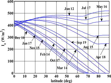
Thus, Ghana’s geographical location predisposes it to high solar radiation (). In this figure, the average monthly daily extraterrestrial radiation on a horizontal surface pointed due south, with monthly mean day numbers is shown.[Citation8] It can be observed that variation throughout the whole year is moderate for Ghana’s latitude as compared with places of higher latitudes.
Figure 1. Monthly hourly mean extraterrestrial radiation on a horizontal surface for North latitude. Ghana is located between 4° and 12°.
This resource has not been harnessed effectively, especially for drying due to the fact that output collector air temperature is not known before construction. Food products that are usually dried in Ghana include cocoa beans, cereals, legumes, leafy vegetables, cassava, yam, cocoyam, plantain, fish, snail, and shrimps. However, currently these are mostly dried in the open sun exposing them to contaminants.
Therefore, any means by which these products could be dried effectively, quickly, and hygienically to make them available during the lean season and to increase its variability of uses in product formulation without compromising on quality would be appropriate. Low temperatures are known to have minimal effect on heat sensitive components of a food product. However, improper design of collector systems may lead to overheating or underheating. Hence, in designing a solar collector for drying purposes with the intention of maintaining nutrition value, parameters such as flow of heating medium, collector dimensions, absorber and cover plates material, and surface type have to be considered.
Continuous drying at night can be possible by introducing an adsorbent (with for example silica gel) in the process. A solar adsorption dryer system (SADS) is an integrated dryer system that utilizes the sun’s energy for drying and regeneration during the day and drying with dehumidified and slightly heated air drying during the night. This represents a new technology. Starting from this new technology a first essential step is a model-based design of flat plate solar collectors and investigating its suitability for drying and regeneration at varying collector length. Tomas et al.[Citation11] mentioned that virtual prototyping of solar collectors helps to predict the performance of a collector before manufacturing. Following this line, the goal here is to base the solar collector design on physical state-space modeling to investigate the collector dimensions that give low air output temperature which may lead to minimal deleterious effect on heat sensitive nutrients during drying during day time and, in addition, to investigate a collector system of dimension suitable for sorbent regeneration. Investigation of design and operational parameters on performance is also considered.
The design of solar collectors for drying finds their basis in the model-based work of Duffie and Beckman.[Citation12] There are, however, several aspects of novelty in the model-based approach of the current study. The earlier literature on solar collectors, such as the seminal work of Duffie and Beckman[Citation12] (and thus most of the subsequent work) was at the time necessarily limited to the use of analytical expressions and approximations. With numerical models, the limitations of this approach can be alleviated. For instance, Duffie and Beckman mention that it is difficult to determine the spatial mean temperature of the absorber plate, which is required to obtain an overall heat loss coefficient. In the spatially distributed model as presented here, this is not a problem at all. Moreover, solar collectors are often characterized by the heat removal factor that must be determined experimentally. This is obviously not of much use when the collector still has to be designed. In more recent papers on solar collector modeling, the focus is on heat gain from solar radiation and heat removal factor (Koyuncu[Citation13]) but surprisingly not enough on the temperature at the outlet. However, the temperature at the outlet is essential for drying sensitive agricultural products (40–50°C), and for regeneration of adsorbents in an adsorption dryer system (50–80°C). Kicsiny[Citation14] modeled the outlet temperatures for an existing solar collector based on experimental data for the environmental conditions, but this approach does not help to design the dimensions of the solar collector, especially solar collectors being operated under different conditions. The current work does include the collector outlet temperature and evaluates the effect of operational factors, such as air speed, and design factors, such as collector length. In addition, the dynamics during the day can be evaluated, in contrast to several steady state analyses in the literature. Heat transfer coefficients are not constant, and change during the day and may be affected by collector length, which is another motivation for the development of a dynamic model. The heat transfer coefficients in the work of some researchers were not investigated as function of time, space and air velocity. Some researchers have reported them as parameters to be estimated (Kicsiny,[Citation14] Gao et al.,[Citation15] Alvarez et al.[Citation16]). In the dynamic model of Buzás et al.[Citation17] spatial distribution is not considered as the collector is considered as a mixed tank. Spatially distributed works that come close to this work are PV/water systems,[Citation18Citation19Citation20] solar tunnel dryer,[Citation21] and solar water heater.[Citation20] This work sought to use a model-based approach to design and construct solar collectors for low and high outlet temperatures in a solar adsorption drying system for drying agricultural products and for regeneration of the adsorbent used for night drying. The models are validated with experimental data from the constructed collector systems.
Solar collector modeling
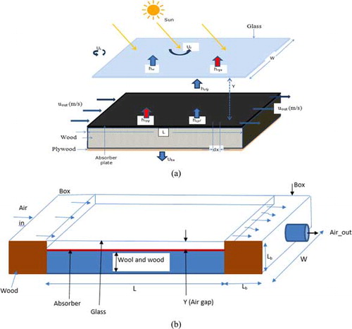
On a solar collector, the incident solar energy is partially absorbed by an absorber plate and subsequently transferred to a flowing medium in an enclosure. One design uses an absorber plate and a glass cover with flowing air in between (). The regime of air flow, whether laminar or turbulent, has an influence on the dynamic behavior of the system. In the present model, the rate of change of air temperature between plates is a function of absorber plate and cover temperatures, air gap, collector length, and air flow rate. On the other hand, the rate of change of absorber (plate) temperature is a function of the external input solar flux, plate temperature, and glass temperature whereas the rate of change of cover plate (glass) temperature is a function of the glass, ambient, and sky temperatures.
Figure 2. Solar collector system showing air flow, insulation, and loss coefficients (a) and air box at the inlet and outlet end beyond the collector (b).
The glass cover, air stream, and absorber plate (aluminum coated black) are modeled using the following assumptions:
Solar absorption is mainly by the absorber plate.
Air flow is in longitudinal direction only (one dimensional).
The temperature equilibration in the directions perpendicular to the flow direction is so fast that there are no temperature gradients in these directions.
Transversal temperature gradients within the glass cover are ignored.
Losses through the front end, back end, and the convective term of the top cover are to ambient temperature whereas the irradiation term of the top cover is to the sky.
Longitudinal dispersion of heat is negligible.
Dust and dirt on the collector are negligible.
Shading of the absorber plate is negligible.
Convective transfer coefficients between absorber plate and air and between air and cover plate (glass) are the same.
The schematic sketch (not to scale) of the solar collector system showing the incident radiation, air flow between glass and absorber plates and the heat transfer coefficients is shown in , and the whole system including air boxes at the inlet and outlet end beyond the collector is shown in . The inlet box is to ensure an even distribution of air over the width of the collector, and the outlet box collects the air for further use.
The inputs are ambient air temperature Ta (°C) and incident radiation I (W m−2) whereas the states are glass temperature Tg (°C), air temperature Tf (°C), and plate temperature Tp, respectively.
Accumulation of heat in the absorber plate is a function of radiation received by absorber plate minus radiation heat lost to the atmosphere through the glass, minus heat transferred to the fluid, minus heat transferred to the back, and edge wall as represented in
The one but last term between the square brackets at the right-hand side stems from the loss through the back of the plate, and the last term from the heat loss at the edges of the plate . As only the back plate is insulated, the heat loss coefficient through insulation materials, wool (ins) and wood (constr), is
For the applied symbols, see the list of symbols. Heat accumulated in the fluid is a function of heat gained in the direction of collector length plus heat gained from plate, minus heat lost to the glass and wall:
The heated air is collected in an end box with dimensions Lb × Lb × W. Assuming complete mixing, the outlet temperature Tb from the box can be described by the following heat balance:
In principle, Eq. (5) can be used as such but a simplification is possible if the time constant is much smaller than the scale of variation of the outside conditions. Equation (5) is a first-order equation with time constant:
With the dimensions of the box and the characteristic air speed of 0.5 m s−1, the time constant is less than 2 s, so the box can be assumed to be in quasi-steady state, which leads to
The temperature of the glass plate is given by the solar heat absorbed by glass, and by radiation received from the plate and lost to the sky, as well as by conductive exchange with the air in the duct as well as with the atmosphere, as described by Eq. (8).
The initial conditions at time to = 0 are Tp(x, to) = Tf(x, to) = Tg(x, to) = Ta(to). The boundary condition is Tf(0, t) = Ta,in(t).
The various differential equations were discretized along the collector length L using finite difference and subsequently solved in Matlab using the Euler backward method. All section lengths are equal and denoted by dx. The total number of sections equals L/dx a typical choice is 45.
Equations (1), (4), (5), and (8) were formulated on the assumption that solar radiation transmitted through the glass cover is absorbed by the absorber plate and heats up the plate to temperature Tp. Heat is lost to ambient at Ta through back, Uk, box and side edge wall loss coefficients Ubs. Energy is gained from the plate by the fluid to temperature Tf through convective heat transfer coefficient hcpf. Energy is lost from the plate to the glass at Tg through irradiation with transfer coefficient hrpg whereas energy is lost from the air to the glass through convective heat transfer with coefficient hcfg. The glass, thus, loses energy to the ambient at Ta through heat transfer coefficient hw which is a function of the wind speed and to the sky at Ts through irradiation by the heat transfer coefficient hrgs. Other researchers have used these heat transfer coefficients as estimated parameters (Kicsiny[Citation14]). In Eq. (8), αg represent the proportion of incident radiation absorbed by glass (0.05). The sky temperature Ts is computed from the ambient air temperature Ta by the relation [Eq. (9)] mentioned by Gao et al.,[Citation15] Swinbank[Citation22] and cited by Hamed et al.[Citation23] and Wolf et al.[Citation24]
The convective heat transfer coefficient within plates are equal as shown in Eq. (10).
The calculation of irradiation heat transfer coefficient between plate and cover glass is based on the common local linearization of the radiative flux and is given by
Similarly, the radiative heat transfer coefficient between the glass and the sky (atmosphere) is
Flow regimes in channels are developed in the initial part of a channel. As a consequence for turbulent flow in relative short channels with aspect ratio [i.e., the ratio of the collector length to hydraulic length (L/DH)] of 10, the actual Nu number is 16% higher, whereas for aspect ratios 30, the Nu number is 5% higher. At L/DH is 100, the effect of entrance region on Nu is insignificant for turbulent flow. However, for laminar flow, the heat transfer coefficient is significantly affected due to development of thermal and hydrodynamic boundary layers. Duffie and Beckman[Citation26] gave for laminar flow the following relationship between the Rayleigh number and Nusselt number, as suggested by Hollands et al.[Citation27] for solar collectors with tilt angles β between 0° and 75°.
The important parameters that are keys in determining the performance of a collector system are the heat loss coefficient, heat gain, and the thermal efficiency. The instantaneous efficiency (i.e., the efficiency at any moment) is given by
The heat gain Qu(t) for the heated air along the collector, is given by
The heat gain is also equal to the difference between heat absorbed, and heat lost to the environment:
The term UL(t) is the instantaneous overall heat loss coefficient and is an important characteristic of the solar air heater. In fact, under the assumption that the rate of heat storage in the material of the collector is small as compared with the other terms, the two heat gains [Eqs. (18) and (19)] should be equal, which provide an operational definition of the actual overall heat loss coefficient as Eq. (21).
The overall heat loss coefficient could be a useful characteristic to compare various designs, on the basis of measurements after the units have been built. Prior to construction, when no data are available on the temperatures, the overall heat loss coefficient has little value as a design parameter.
Results and discussion
Model-based solar collector design and analysis
Design and analysis calculations have been performed with the default nominal parameters as given in (the engineering toolbox) and using representative inputs and operational conditions. To solve the partial differential equations, the solar collector was discretized in 45 sections of equal length, and for each section, Eqs. (1), (4), (5), and (8) were solved in time. The calculations were performed with the differential equation solver “ode45” of Matlab. The varying input conditions to the model are the ambient temperature Ta,in(t) and the radiation I(t). gives an example of the variation of these inputs over the simulation time. This figure starts with the use of the system at 8.00 h in the morning. The simulation is stopped at around 17.00 h. The linear air flow velocity was 0.5 m s−1, and after evaluation of different air gaps, the value was set to 0.025 m. The collector width was set to 1 m.
Figure 3. Model inputs ambient air temperature and solar radiation on February 3, 2013.
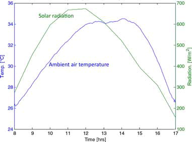
Table 1. Parameter values.
Effect of absorber surface on performance
The surface properties of an absorber plate have some influence on the absorbed radiation as well as the energy loss (Gao et al.[Citation15]). A selective surface can improve the efficiency of a solar thermal collector system, in that it rather emits less infrared radiation than absorbed solar radiation. However, a nonselective surface absorbs more radiation and emits almost the same percentage of infrared radiation. In this work, a nonselective black-coated absorber surface was used. The nominal values for the fraction of absorbed solar radiation (αp) and the thermal radiation emitted (εp) from the absorber plate used were set to 0.95 and 0.90, respectively. The solar absorption coefficient is not exactly known, but as it is an important parameter, it is later adjusted on the basis of the experimental data (see section “Experimental verification and validation”).
Effect of collector length on temperature
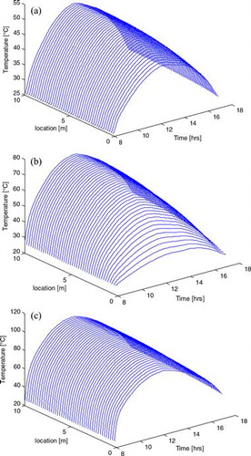
shows the 3D plots of modeled temperature as a function of time and space with ambient air and radiation of a representative day as input (data of February 3, 2013). The variation of air temperature along the collector length was higher than that of glass and absorber plate. The main gain in air temperature is achieved in the initial part of the collector (between 0 and 1.5 m), and in a long solar collector (over 4.5 m), the gain in temperature becomes marginal towards the end. It implies that increasing collector length beyond a certain value does not lead to a sufficient increase in air temperature. This information helps determine the suitability of a particular collector length to yield a predetermined collector output air temperature. A temperature level between 40 and 50°C during a main part of the day was considered as sufficient for solar-aided drying, and for this purpose, a collector length of 1.5 m was appropriate.
Figure 4. Temperature profile of glass (a), air (b), and plate (c) at varying collector length for February 3, 2013.
The water holding (adsorption) capacity of silica gel at ambient conditions (25–30°C, 60–80% relative humidity) is about 20% water/kg dry silica gel, whereas at temperatures above 50°C, the holding capacity is below 5% water/kg dry silica gel.[Citation28] These properties allow a cycle of adsorption and desorption of water to silica gel. For the cycle, it is required that the solar collector is long enough to reach temperatures above 50°C during several hours a day. This is achieved during the main part of the day by a collector length of 4.5 m.
Construction of collector equipment
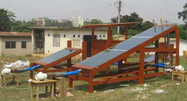
The model output indicated that collectors of lengths 1.5 and 4.5 m were suitable for drying and regeneration, respectively. The efficiency of solar collectors is influenced by the tilt angle. From the data of Perez et al.,[Citation29,Citation30] it was concluded that a 25° tilt angle is most effective for the latitude of Ghana. Based on this information, two collectors (for drying and regeneration) tilted at 25° were constructed in Ghana as shown in .
Figure 5. Collector systems: photo of construction showing the position of the fans pointed due south.
Effect of design decisions
represent the simulated spatially distributed Nusselt number (Nu), Rayleigh number (Ra), convective heat transfer coefficient between plates (hcpf), radiative heat transfer coefficient between plates (hrpg), and sky (hrgs) as a function of time for the collector length of 1.5 m. In this figure, all the coefficients have minor variations in length and strong variations over the operational time. Hence, for the design of solar collectors, the temporal variations of these coefficients, due to the changing radiation input and environmental air temperatures, are more important than the spatial variations. This also implies that models that use time-invariant numbers are a gross simplification.
Figure 6. Nusselt number, Rayleigh number, and heat transfer coefficients against space and time for 1.5 m collector length.
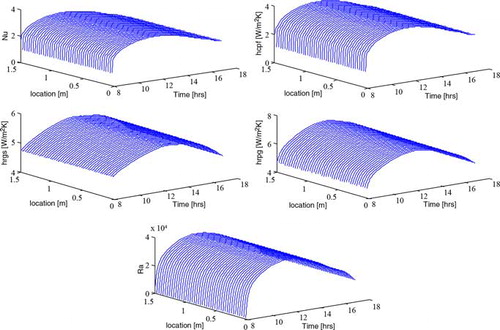
The radiation heat transfer coefficient values between the plates were higher than the convective heat transfer coefficient values due to the nonselective coating surface properties of the absorber. The nonselective absorber surface exhibited more thermal radiation emission than convective loss, thus making the radiative loss component dominant (Mintsa Do Ango et al.[Citation31] and Gao et al.[Citation15]). Bhagoria et al.[Citation32] and Gao et al.[Citation15] propose the use of rough surfaces to improve the convective heat transfer coefficient. In the natural convection and analytical approach of Gao et al.[Citation15] in which a flat absorbing and flat bottom plates were used as the air flow channels, constant values of hrgs, hrpg, and hcpf reported were, respectively, 12.4, 5.9, and 8.8 W m−2 K−1. These values were obtained for one set of conditions during a day. From the simulations in this work, the outlet hrgs, hrpg, and hcpf as function of day time are reported to be in the range of 4.75–5.60, 1.16–3.89, and 4.65–7.19 W m−2 K−1, respectively. So, application of values obtained by parameter estimation at one time of the day may lead to errors when applied to the daily cycle.
Collector performance
shows the thermal efficiency (a), heat gain (b), mean plate temperature (c), and overall heat loss coefficient (d), respectively. Just as the transfer coefficients, these values vary over the day. Moreover, the performance is a function of the collector length. While increasing the length of the collector, the incoming amount of energy increases proportionally. During the passage of the air through the collector, however, the air temperature comes closer to the plate temperature so that the driving force for heat transfer between plate and air decreases.
Figure 7. Collector performance: (a) efficiency; (b) heat gain; (c) mean plate temperature (Tpm); (d) heat loss coefficient (UL) for 1.5, 4.5, and 10 m collector length dated February 3, 2013.
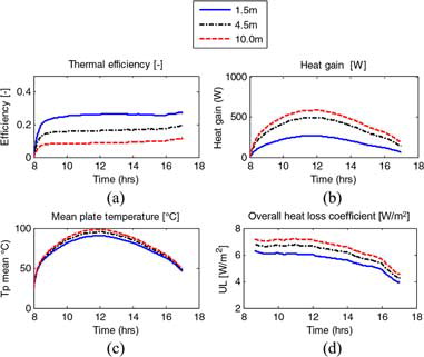
As a consequence, the heat gain () does not increase proportionally along the length of the collector. Therefore, the efficiency decreases and the heat loss coefficient increases with the collector length ( and ). Although these findings are easy to understand from a physical point of view, several authors report heat loss coefficients or efficiencies from experimental work. From this work, it can be stated that observed loss coefficients and efficiencies, though perhaps useful for comparing alternative designs, are not meaningful for collector design because they depend on the design choices. For example, the range of the overall heat loss coefficient (UL) at increasing collector length is between 4.3 and 7.7 W m−2 K−1 compared with 15 and 24 W m−2 K−1 by Koyuncu[Citation13] and 5.5 W m−2 K−1 by Santos et al.[Citation33] The very different values underline the unsuitability of the heat loss coefficient (UL) as design parameter.
It may be noted that the heat gain between the collector lengths of 1.5 and 4.5 m is more than between 4.5 and 10 m as has earlier been mentioned. Mintsa Do Ango et al.[Citation27] mentioned that collector length has no effect on collector performance, which is at variant with the present work.
Effect of air speed on collector performance
One of the operational parameters that affect the performance of a solar system is the flow of air. The impact of the air velocity on the mean plate, air, and glass outlet temperatures for the day is investigated (). illustrates that mean plate and glass temperatures are moderately affected by the air velocity whereas the air temperature is strongly affected. The decrease of air temperature with increasing air velocity is result of heating a higher amount of air by the same amount of solar energy.
Figure 8. (a) Day averaged solar collector temperatures for plate (Tp), air (Tf), and glass (Tg). (b) Heat gain and thermal efficiency. Both as function of air velocity for 1.5, 4.5, and 10 m collector lengths.
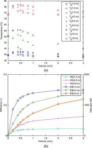
Lower air temperatures enhance the heat transfer from plate to the air, and hence, the thermal efficiency and heat gain improve and the overall loss coefficient decreases. Variable point of equilibration of efficiency/heat gain has been reported in the literature due to differences in design dimensions. In the present work, beyond 1 m s−1 velocity, equilibration starts for all parameters studied whereas Lin et al.[Citation34] reported a value of 0.6 m s−1.
In addition, the turbulence of air can further be improved using a rough or corrugated surface (Gao et al.[Citation15]) to increase the convective heat transfer coefficient between plates and if possible a high selective black coating to improve the air temperature as well as the thermal efficiency and heat gain.
In the SADS that forms the motivation for this work, the dryer requires a temperature of about 40–50°C whereas a temperature well over 50°C is required for the adsorbent regeneration system. These conditions are well reached for the design flow of 0.5 m s−1 with collector lengths of 1.5 and 4.5 m, respectively.
Experimental verification and validation
Description of the experiments
Experiments were conducted to verify the output responses of the two collectors. The ambient inlet and the outlet temperatures for both collectors were logged during three experimental days (February 3–5, 2013 from 8:00 to 17:00 h) at 5 s interval using Labview as interface. The data were smoothed using a moving average method to remove high-frequency measurement noise. The ambient temperature and interpolated values of the hourly radiation data for the 3rd of February were used to test the model, and to make adjustments of the plate solar absorption coefficient. The data of February 4 and 5 served as validation data.
Model verification and parameter adjustment
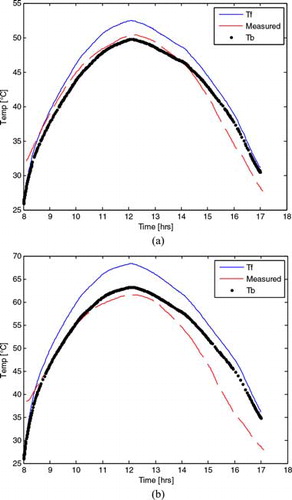
Application of the model on the data of February 3, 2013, with the nominal parameters resulted in somewhat higher temperatures than really observed. Obviously, there are uncertainties in a large number of parameters, and to some extent adjustment can be made on both the gain side (solar absorption) as well as the loss side (heat loss coefficients). The data have been collected primarily with the intention to test whether predicted collector lengths were suitable for the intended purposes (drying and adsorbent regeneration). The data are rich enough for this purpose but not rich enough for the purpose of a formal full parameter estimation. As the heat transfer coefficients have a well-established basis, it was decided to just adapt the solar absorption coefficient by the plate, as this was essentially unknown. An adjustment from the nominal value of 0.95–0.88 was sufficient to obtain the fit shown in . The figure also shows the effect of the final collector box. On retrospect, it appears that the lack of insulation of the end box of the collector causes a considerable temperature drop. It is also observed that in the afternoon, the model has slightly higher temperatures than observed in the real system. From the data, there is no obvious explanation. Note that small changes in sky temperature may already have an appreciable effect on the temperature, but as no further information is available, this cannot be substantiated further. Overall, in view of the fact that just one parameter was adjusted, the fit is quite satisfactory.
Figure 9. Outlet air temperatures for 1.5 m (a) and 4.5 m (b) lengths for temperatures just after collector (Tf), box (Tb), and experiment (measured) taken from February 3, 2013.
Validation
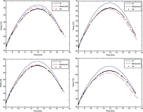
Without further adjustment, the model was then applied to the data of February 4 and 5, 2013. The results are shown in . Given the limitations, the model predicts well for both collector lengths. The main error for both collectors was obtained after 13 h corresponding to a higher increase in the ambient temperature. It should be noted that these results were obtained using physical parameters directly derived from the dimensions and other properties, without any further calibration except for the absorption coefficient. As impression of the quality of the fit, the error index has been computed, i.e., the integral of the absolute difference between model and data relative to the integral of the measurements, expressed as percentage. The error for the 1.5 m collector was between 3 and 6%, whereas that for the 4.5 m was between 8 and 10% for the dates February 3–5, 2016.
Figure 10. Validation of model with αp = 0.88. Outlet air temperatures for 1.5 m (left) and 4.5 m (right) lengths for temperatures just after collector (Tf), box (Tb), and experiment (measured) taken from February 4–5, 2013 (respectively top and bottom).
Discussion
A modeling and simulation study approach was used to construct solar collector systems suitable for drying and regeneration in a SADS. The generic spatially discretized model proved to be a versatile tool to guide solar collector design and operation. The results for the temperature distribution in the given experimental setups suggest that a simplification of the model might be possible by spatial lumping of the glass cover and plate temperatures, but this does not hold for the air temperature along the length of the collector. On the other hand, similarly to the treatment of the box temperature, it might be acceptable to handle the spatial air temperature along the collector as being in pseudo-steady state. Such simplifications may be useful in applications in which computational speed is relevant, such as formal parameter estimation or optimization studies. The experience with the current fully dynamic model, however, shows that for the current purpose, such simplifications are unnecessary. Parameters obtained from physical knowledge already provide a good fit to experimental data. The current choice to only adapt the absorption parameter is not the only possibility, but if the goal would be to investigate details of the heat transfer, more data, in particular, air temperatures along the collector, and distance measurements of the plate temperature, should be recommended to allow for more formal parameter estimation.
Conclusion
Experiments conducted on collectors with air path lengths of 1.5 or 4.5 m indicated a good comparison between the model and observed data, just on the basis of physical parameters without further calibration, except for the solar absorption coefficient of the collector plate.
The modeling exercise makes it clear that increasing the collector length beyond a certain limit makes it inefficient due to decreasing driving force for heat transfer between plate and air.
The findings of this work indicate that plate and glass temperatures as well as heat transfer coefficients are practically independent of the length and are weak functions of air velocity. In contrast, the overall heat loss coefficient, heat gain, and efficiency are highly dependent on the operational air velocity. In addition, it was shown that heat transfer coefficients and the overall heat loss coefficient vary considerably during the day. Therefore, designing a solar collector based on a general number of the heat loss coefficient is not feasible, and fixed heat loss coefficients as reported in the literature have little to offer for the design of a new collector. Empirical approaches based on constant values are gross simplifications. The study shows that these limitations can be overcome using a physical model. Finally, the primary goal, namely to know which collector lengths would be needed for drying and adsorbent regeneration, was reached. The model indicated that under conditions prevailing at the latitude of Ghana, a collector length of 1.5 m gives drying temperatures suitable for drying of heat-sensitive agricultural products at air speed of 0.5 m s−1, and this was confirmed by the experiments. Likewise, a collector of 4.5 m length at an operational air speed between 0.2 and 0.5 m s−1 is suitable for adsorbent (silica gel) regeneration.
Nomenclature
| Ac | = | area of collector (m2) |
| Cp | = | specific heat capacity (J kg−1 K−1) |
| DH | = | hydraulic diameter (m) |
| dx | = | discretized plate length (m) |
| g | = | acceleration due to gravity (m−2) |
| h | = | heat transfer coefficient (W m−2 K−1) |
| I | = | irradiance (W m−2) |
| L | = | total plate length (m) |
| Lb | = | edge dimension of the receiving box (m) |
| Nu | = | Nusselt number |
| p | = | combined parameter |
| Pr | = | Prandtl number |
| Qu | = | useful heat gain (W) |
| Ra | = | Rayleigh number |
| Re | = | Reynolds number |
| T | = | temperature (K) |
| ▵T | = | temperature difference (K) |
| u | = | velocity (m s−1) |
| Uk | = | back loss coefficient (W m−2 K−1) |
| UL | = | overall loss coefficient (W m−2 K−1) |
| Uwall = Ubs | = | box or side wall loss coefficient (W m−2 K−1) |
| W | = | width of plate (m) |
| Y | = | air gap between plate and glass cover (m) |
| Yp | = | thickness of plate (m) |
| Yg | = | thickness of glass (m) |
| Greek letters | ||
| α | = | absorbance of radiation (—) |
| α* | = | thermal diffusivity (m2 s−1) |
| β | = | slope of plate (°) |
| ε | = | emissivity (—) |
| ŋ | = | collector efficiency (—) |
| λ | = | thermal conductivity (W m−1 K−1) |
| ξ | = | volumetric coefficient of expansion (K−1) |
| ρ | = | density (kg m−3) |
| σ | = | Stephan–Boltzmann constant (W m−2 K−4) |
| τ | = | transmittance (—) |
| υ | = | kinematic viscosity (m2 s−1) |
| Φ | = | volumetric flow rate (m3 s−1) |
| Subscripts | ||
| a | = | ambient |
| b | = | receiving air box |
| c | = | convective |
| col | = | collector |
| constr | = | construction material (wood) |
| e | = | side wall |
| f | = | flowing medium, i.e., air |
| g | = | glass cover |
| in | = | input |
| ins | = | insulation (wool) |
| k | = | absorber insulation |
| m | = | mean |
| p | = | plate |
| r | = | radiative |
| s | = | sky |
| w | = | wind |
References
- Fellow, P. Food Processing Technology: Principles and Practice, 2nd ed.; Wood Head Publishing Limited: Cambridge, England, 2000, 330.
- Fellow, P. Food Processing Technology: Principles and Practice; Wood Head Publishing Limited: Cambridge, England, 2009, 481.
- Doymaz, I. Drying kinetics of white mulberry. Journal of Food Engineering 2004, 61, 341–346.
- Hofsetz, K.; Lopes, C.C.; Hubinger, M.D.; Mayor, L.; Sereno, A.M. Changes in the physical properties of bananas on applying HTST pulse during air drying. Journal of Food Engineering 2007, 83, 531–540.
- Ozcan, M.; Arslan, D. Effect of drying methods on the mineral content of basil (Ocimum basilicum L.). Journal of Food Engineering 2005, 69, 375–379.
- Mujumdar, A.S. Innovation in drying. Drying Technology 1996, 14, 1459–1475.
- Atuonwu, J.C.; van Straten, G.; Deventer, H.C.; van Boxtel, A.J.B. Improving adsorption drying energy efficiency by simultaneous optimization and heat integration, Drying Technology 2011, 29, 1459–1471.
- Akuffo, F.O. Climatic Data for Solar and Wind Energy Application in Ghana, Vol. 2; Ministry of Energy: Ghana, 1991; 1–22.
- Akuffo, F.O.; Brew-Hammond, F.O.; Antonio, A.; Forson, J.; Edwin, F.; Sunnu, I.A.; Akwensivie, A.; Agbeko, F.; Ofori, K.E.; Appiah, F.K. Solar and Wind Energy Resource Assessment (SWERA); Energy Commission: Ghana, 2003; 1–44.
- Edjekumhene, I.; Atakora, S.B. Implementation of Renewable Energy Resources – Opportunities and Barriers, Ghana Country Study; UNEP, Riso National Laboratory: Roskilde, Denmark, 2001, 48.
- Tomas, M.; Vladimir, Z.; Juliane, M. Detailed modeling of solar flat-plate collectors with design tool kolektor 2.2, building simulation. In Eleventh International IBPSA Conference, Glasgow, Scotland; IBPSA: Loughborough, UK, 2009; 2289–2296.
- Duffie, J.A.; Beckman, W.A. Solar Engineering of Thermal Processes, 2nd ed.; John Wiley & Sons, Inc.: New York, 1980; 23, 73–74, 95–101.
- Koyuncu, T. Performance of various design of solar air heaters for crop drying applications. Renewable Energy 2006, 31, 1073–1088.
- Kicsiny, R. Improved multiple linear regression based models for solar collectors. Renewable Energy 2016, 91, 224–232.
- Gao, W.; Lin, W.; Liu, T.; Xia, C. Analytical and experimental studies on the thermal performance of cross-corrugated and flat plate solar air heaters. Applied Energy 2007, 84(4), 425–441.
- Alvarez, A.; Cebaza, O.; Muñiz, M.C.; Varela, L.M. Experimental and numerical investigation of a flat-plate solar collector. Energy 2010, 35, 3707–3716.
- Buzás, J.; Farkas, I.; Biró, A.; Németh, R. Modelling and simulation of a solar thermal system. Mathematics and Computers in Simulation 1998, 48, 33–46.
- Chow, T.T.; He, W.; Ji, J. Hybrid photovoltaic-thermosyphon water heating system for residential application. Solar Energy 2006, 80, 298–306.
- Ji, J.; He, H.; Chow, T.; Pei, G.; He, W.; Liu, K. Distributed dynamic modeling and experimental study of PV evaporator in a PV/T solar-assisted heat pump. International Journal of Heat and Mass Transfer 2009, 52, 1365–1373.
- Tiwari, A.; Sodha, M.S. Parametric study of various configurations of hybrid PV/thermal air collectors: Experimental validation of theoritical model. Solar Energy Materials and Solar Cells 2007, 91, 17–28.
- Talbot, P.; Lhote, M.; Heilporn, C.; Schubert, A.; Willaert, F.-X.; Haut, B. Ventilated tunnel solar dryers for small-scale farmers communities: Theoretical and practical aspects. Drying Technology 2016, 34, 1162–1174.
- Swinbank; W.C. Long wave radiation from clear skies. Quarterly Journal of the Royal Meteorological Society 1963, 89, 339–348.
- Hamed, M.; Fellah, A.; Brahim, A.B. Parametric sensivity studies on the performance of a flat plate solar collector in transient behaviour. Energy Conservation and Management 2014, 78, 938–947.
- Wolf, D.; Kudish, A.I.; Sembira, A.N. Energy 1981, 6, 333–349.
- McAdams, W.H. Heat Tansmission; McGraw-Hill: New York, 1954.
- Duffie, J.A.; Beckman, W.A. Solar Engineering of Thermal Processes; John Wiley & Sons, Inc., 1991, 23–41, 73–74, 95–101.
- Hollands, K.G.T.; Unny, T.E.; Raithby, G.D.; Konicek, L. Free convective heat transfer across inclined air layers. Journal of Heat Transfer 1976, 98, 189–192.
- van Boxtel, A.J.B.; Boon, M.A.; van Deventer, H.C.; Bussmann, P.J.Th. Zeolites for Reducing Drying Energy Usage, In Modern Drying Technology; Chapter 5, Vol. 4; Wiley-Verlag GmbH & Co.: Weinheim, Germany, 2014.
- Perez, R.; Seals, R.; Ineichen, P.; Stewart, R.; Menicucci, D. A new simplified version of the Perez diffuse irradiance model for tilted surfaces. Solar Energy 1987, 39, 221.
- Perez, R.; Stewart, R. The development and verification of the perez diffuse radiation model. Sandia National Laboratories Contractors Report (SAND88–7030), 1988.
- Mintsa Do Ango, A.C.; Medale, M.; Abid, C. Optimization of the design of a polymer flat plate solar collector. Solar Energy 2013, 87, 64–67.
- Bhagoria, J.L.; Saini, J.S.; Solanki, S.C. Heat transfer coefficient and friction factor correlations for rectangular solar air heater duct having transverse wedge shaped rib roughness on the absorber plate. Renewable Energy 2002, 25(3), 341–369.
- Santos, B.M.; Queiroz, M.R.; Borges, T.P.F. A solar collector design procedure for crop drying. Brazilian Journal of Chemical Engineering 2005, 22(2), 277–284.
- Lin, W.; Gao, W.; Liu, T. A parametric study on the thermal performance of cross corrugated solar air collectors. Applied Thermal Engineering 2005, 26(10), 1043–1053.