Abstract
Rapid prototyping (RP) is a common name for several techniques, which read in data from computer-aided design (CAD) drawings and manufacture automatically three-dimensional objects layer-by-layer according to the virtual design. The utilization of RP in tissue engineering enables the production of three-dimensional scaffolds with complex geometries and very fine structures. Adding micro- and nanometer details into the scaffolds improves the mechanical properties of the scaffold and ensures better cell adhesion to the scaffold surface. Thus, tissue engineering constructs can be customized according to the data acquired from the medical scans to match the each patient's individual needs. In addition RP enables the control of the scaffold porosity making it possible to fabricate applications with desired structural integrity. Unfortunately, every RP process has its own unique disadvantages in building tissue engineering scaffolds. Hence, the future research should be focused on the development of RP machines designed specifically for fabrication of tissue engineering scaffolds, although RP methods already can serve as a link between tissue and engineering.
Introduction
Tissue engineering is an interesting emerging area of science. It can be defined as the science and engineering of functional tissues and organs for the repair of diseased body parts. Autologous tissue-engineered devices are formed by combining patient-derived cells with a degradable material and implanting the combination in the body. The material is termed a scaffold or matrix. It is porous or gelatinous in nature ensuring the incorporation of cells within the substrate and not solely on the surface Citation1. Tissue engineering has attracted a lot of attention in the past decade due to its potential capability to produce biological substitutes that restore, maintain, or improve tissue function. The main focus of tissue engineering has turned away from mere cell culturing towards developing three-dimensional structures that support the proliferation, migration and differentiation of cells obtained from cell cultures Citation2. The goal of tissue engineering is to circumvent the limitations of conventional clinical treatments for damaged tissue or organs based on the use of organ transplants or biomaterial implants. The most essential limitations of these treatments involve shortage of donor organs, chronic rejection, and cell morbidity Citation3, Citation4.
The dominant method of tissue engineering appears to involve growing the relevant cells in vitro into a scaffold that attempts to mimic the function of the natural extracellular matrix. Without any three-dimensional supporting structures the cells will form a random two-dimensional mainly monolayer of cells. Thus the primary function of a scaffold is to serve as an adhesion substrate for the cells. In addition the scaffold provides temporary mechanical support and guidance to the growing tissue Citation4. Several requirements exist that a successful scaffold must meet: 1) the scaffold should have interconnecting pores that enable supply of nutrients and metabolites as well as cell ingrowth; 2) the pore size should be in the range of 5–10 times of the cell diameter, e.g. 100–300 µm; 3) the surface chemistry of the scaffold should favor cellular attachment, differentiation, and proliferation; 4) the scaffold should be made of a material with appropriate rate of degradation in order to allow the surrounding tissue eventually replace the scaffold; and 5) the scaffold should be easily fabricated into various shapes and sizes Citation2–5.
Key messages
As an alternative to conventional scaffold fabrication methods, a group of techniques called rapid prototyping (RP) techniques have been introduced within the tissue engineering field.
RP technologies are based on an additive process in which complex scaffold features are constructed automatically in a layer-by-layer manner according to computer-aided design (CAD) data obtained from a patient's medical scans.
Advantages of using RP processes in constructing scaffolds include customization of the products to meet the individual needs, ability to create complex geometries and high-accuracy features, and possibility to control pore size and distribution of pores within the scaffold.
Abbreviations
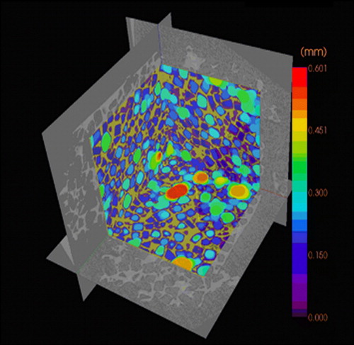
According to these requirements scaffolds have been produced in various ways, both by using conventional scaffold fabrication techniques and more advanced methods. Conventional methods for scaffold fabrication include techniques such as solvent casting and particulate leaching, gas foaming, fiber meshes and fiber bonding, phase separation, melt molding, emulsion freeze drying, solution casting and freeze drying. Unfortunately there are several limitations involving these processing methods. Conventional methods are incapable of precisely controlling pore size, pore geometry, pore interconnectivity, spatial distribution of pores, and construction of internal channels within the scaffold Citation3, Citation4. For example, scaffolds fabricated by the combination of photopolymerization and salt leaching often contain inhomogeneities of pore distribution (). The pore size distribution can be visualized by microCT scanner, which reveals a quite irregular distribution of pores in the scaffold (). In addition many of these techniques exploit organic solvents, like chloroform or methylene chloride, as a part of the process to dissolve synthetic polymers. The presence of organic solvent residues is a significant problem of conventional fabrication methods due to toxins and carcinogens to which cells are exposed if residual solvent exists Citation3.
Figure 1. MicroCT analysis of salt-leached, photopolymerized scaffold fabricated with Kerr dental lamp. The material was methacrylate end-capped poly(D,L-lactide), and camphorquinone has been used as photoinitiator.
Figure 2. Pore size distribution of the photopolymerized scaffold visualized by microCT.
Advanced scaffold fabrication methods
As an alternative to conventional scaffold fabrication methods, a group of techniques called rapid prototyping (RP) techniques has recently been introduced within the tissue engineering field. RP technologies is a common name for a number of advanced manufacturing techniques that are based on an additive process in which complex structures are constructed in a layer-by-layer manner according to a computer program Citation6. The phrase rapid prototyping was used for the first time in the early 1980s. Since then a large variety of applications has seen the daylight. Everything from automotive engine parts to small telecommunication industry components have been fabricated by these new means. However, it took until the 1990s before rapid prototyping techniques were adapted into the medical and biomedical fields Citation7.
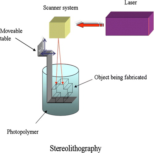
All the RP techniques are based on the use of computer-aided design (CAD) information that is converted to an.STL type file format. This format is derived from the name stereolithography, the oldest of the RP technologies. The file format has been accepted as the golden standard of the industry. Basically, CAD data are converted into a series of cross-sectional layers. These computer generated two-dimensional layers are then created as a solid model by a variety of processes. Starting from the bottom and proceeding upwards, each layer is glued or otherwise bonded to the previous layer, thus producing a solid model of the object presented on the computer screen Citation7, Citation8.
In addition, data obtained from computerized tomography (CT) or magnetic resonance imaging (MRI) medical scans can be used to create customized CAD models. The desired implant area of the patient is scanned by CT or MRI, and the data are imported into CAD software. The software enables a surgeon to design an implant according to individual needs. After the information is transferred to a RP system, a biocompatible and biodegradable scaffold is fabricated Citation2, Citation8.
Over the past two decades more than 20 RP systems have been developed and commercialized. Basically, these layering methods fall into three basic types: liquid-based, solid-based, and powder-based RP systems. Liquid-based technologies include stereolithography and two-photon polymerization, whereas fused deposition modeling is a solid-based system. Selective laser sintering and 3D printing fall in the category of powder-based methods. The selection of material choices ranges from paper to various polymers, ceramics, and metals Citation6, Citation7.
RP techniques used in bone and cartilage applications
The first applications of RP techniques in medical field were primarily implants used in craniomaxillofacial surgery. Although a method for producing patient skull models and prosthesis has been described, the applications were limited to surgical planning rather than manufacture of actual cranioplasts. These models allowed a surgeon to plan the entire operation beforehand and to predict the appearance of the outcome for the first time Citation7, Citation9. Proper tissue engineering applications were pioneered by Griffith and co-workers at Massachusetts Institute of Technology (MIT). In 1996 Griffith and Halloran reported the fabrication of ceramic parts by stereolithography (SLA). Ultraviolet (UV) photocurable monomer was loaded with suspensions of alumina, silicon nitride, and silica particles. The monomer was cured by UV laser beam that was guided according to the CAD cross-sectional data (). A green body was formed as a result of bonding of the ceramic particles. The polymer binder was removed by pyrolysis and the ceramic parts sintered. The same technique was used by Levy et al. to fabricate hydroxyapatite (HA) scaffolds for orbital floor implants. All the ceramic scaffolds are limited to bone tissue engineering Citation3. Stereolithography has also been successfully utilized to build bone tissue scaffolds from photo-cross-linkable poly(propylene fumarate) (PPF). It can be cross-linked through its carbon-carbon double bonds, and it degrades in the body by simple hydrolysis of the ester bonds into nontoxic products. Still, both in vitro and in vivo biological evaluations of the 3D scaffolds fabricated must be conducted to further optimize pore size and porosity of the bone scaffolds Citation10.
Figure 3. Schematic representation of the stereolithography (SLA) system. An ultraviolet (UV) laser is used to solidify the model's cross-section while leaving the remaining areas in liquid form. The movable table then drops by a sufficient amount to cover the solid polymer with another layer of liquid resin.
The development of biomimetic bone substitutes is a growing field of research. Although significant work has already been done in this field, scientists have not yet introduced an ideal bone graft that could fully mimic the human bone. Ideally, bone grafts should be porous, be able to promote new bone formation, and they should possess proper mechanical and physical properties. A great variety of materials has been used for replacement and repair of damaged bone tissue. These materials include metals, ceramics, polymers (natural and synthetic), and their combinations. Bioceramics are preferred materials as bone grafts due to their low density, chemical inertness, high wear resistance, excellent tissue adherence, and similarity with natural bone. Polymeric and ceramic materials can be resorbable in biological environment Citation11, Citation12.
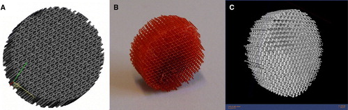
Although various synthetic materials for bone replacement are available today, these materials are produced in simple geometries like blocks, pins, or splines. It has been suggested that a minimum pore size of 100 µm is required for mineralized tissue ingrowth. Thus, the need for new scaffold manufacturing techniques with the ability to control the pore size has emerged Citation13. A more complex polymeric scaffold fabricated by stereolithography is presented in the . The scaffold design is an assembly of prisms with horizontal struts of 80 µm and vertical struts of 800 µm. The scaffold was built of trimethylpropane tetraacrylate on the Envisiontec's Perfactory® SLA machine. The microCT scan reveals that the scaffold has a very regular pore size distribution in the range of 315–659 µm Citation14.
Figure 4. Example of a scaffold fabricated using stereolithography (SLA). A: Computer-aided design (CAD) image of the structure. B: Completed SLA-fabricated scaffold with very regular pore size distribution. C: Microcomputerized tomography (microCT) image of the scaffold.
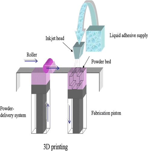
Furthermore, the outer shape of the scaffold can be designed to fit the patient's defect. Especially 3D printing (), developed at the MIT, has been utilized to fabricate custom-tailored scaffolds. The main advantage of this technique is its ability to produce an implant directly from 3D data in one step without using an additional mold. The technique employs conventional inkjet printing technology. During the fabrication a liquid binder is ejected from a printer head onto a thin layer of powder according to the sliced 2D profile of a computer model. The function of the binder is to join adjacent powder particles together thus forming the complete 3D structure. A key requirement for 3D printing of tissue engineering scaffolds is the availability of biocompatible powder-binder systems. Bonelike calcium phosphates are known as highly biocompatible materials, and recently they have been adapted to 3D printing technology and used without the need to utilize cytotoxic organic solvents. The matrices generated by 3D printing are seeded with patient-derived cells and eventually implanted into the body. Besides ceramics, scaffolds from polymers can be fabricated with 3D printing process Citation15, Citation16.
Figure 5. Scheme of 3D printing process. A stream of adhesive droplets is expelled through an inkjet printhead, selectively bonding a thin layer of powder particles to form a solid shape.
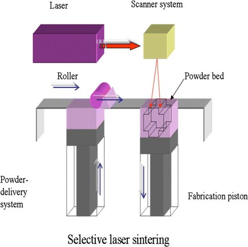
On the other hand, selective laser sintering (SLS) () may be advantageous for creating bone tissue engineering constructs for sites such as the temporomandibular joint (TMJ). It provides a cost-effective, efficient method to construct scaffolds to match the complex anatomical geometry of craniofacial or periodontal structures. Virtually any powdered biomaterial that will fuse but not decompose under a laser beam can be used to fabricate scaffold by SLS. Additionally, SLS does not require the use of any organic solvent. For example Williams et al. have applied SLS to fabricate scaffolds from polycaprolactone (PCL). PCL is a biodegradable polymer with potential applications for bone and cartilage repair. Compared to other polymers such as polylactides (PLA), it is more stable in ambient conditions, less expensive, and readily available in large quantities. The SLS fabrication technique has been successfully used to construct prototypes of minipig's and human's mandibular condyle scaffolds. These scaffolds replicated the desired anatomy well, and they could be manufactured within 3 hours Citation17, Citation18.
Figure 6. Scheme of selective laser sintering (SLS) technique. The laser selectively fuses powdered material by scanning cross-sections generated from a 3D digital description of the part on the surface of a powder bed. After each cross-section is scanned, the powder bed is lowered by one layer thickness, a new layer of material is applied on top, and the process is repeated until the part is completed.
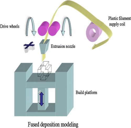
A group of engineers and doctors from the National University of Singapore and National University Hospital has developed a PCL scaffold that can be used as a bone patch to repair holes in the skull. The team has utilized the fused deposition modeling (FDM) rapid prototyping process in creating these 3D scaffolds Citation19. The FDM process () forms objects by operating the extrusion head in the x- and y-axes while the platform lowers in the z-axis for each new layer to form. The head extrudes the semiliquid state thermoplastic polymer in ultrathin layers precisely into place. The extruded material solidifies and adheres to the preceding layer. Burr whole plugs fabricated by FDM have been studied over 5 years in a clinical setting, and they have gained Food & Drug Administration (FDA) approval during 2006. The PCL scaffolds have been used in a pilot study for cranioplasty, and the clinical outcome after 12 months has been positive. Encouraged by the success in clinical trials, the research group set up a spin-off company called Osteopore International to market the new bone patch named BurrPlug™ Citation5, Citation20.
Figure 7. Scheme of the fused deposition modeling (FDM) system. FDM uses a moving nozzle to extrude a fiber of polymeric material from which the physical model is built layer by layer.
Although several polymers have been investigated for bone tissue engineering, no single polymer can satisfy all the requirements of a bone substitute. On the other hand, composite materials may offer a future solution to the problems involving individual materials. In fact, natural bone matrix is an organic/inorganic composite of collagen and apatites Citation12. Polymer-ceramic composite materials incorporate the desirable properties of each of the constituent materials, such as the high wear resistance of ceramics and the toughness of polymers. One example of such is a particulate-reinforced polymer-ceramic composite that was developed by mixing polypropylene (PP) and tricalcium phosphate (TCP). Controlled porosity scaffolds with different complex internal architectures were fabricated via FDM process. According to the in vitro test results these experimental scaffolds were nontoxic and possessed excellent cell growth characteristics Citation11. A problem, however, may be that the scaffold is not biodegradable in the body.
The poor natural healing process of cartilage injuries has accelerated the development of innovative approaches to repair injured cartilage. Recently, tissue engineering has offered reasonable potential to solve the problems related to attempts to repair cartilage with tissue transplants. So far only a few research groups have produced scaffolds for articular cartilage tissue engineering applications using rapid prototyping techniques. There is a strong possibility that since hard tissue replacement has proven successful by FDM-based scaffolds, also cartilage repair could be possible by FDM technique Citation21.
RP systems utilized in fabrication of soft tissue scaffolds
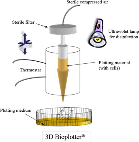
A much more versatile system than FDM has been available since 1999. This 3D Bioplotter® is capable of extruding hotmelts, solutions, pastes, dispersions, polymers, monomers or reactive oligomers. Probably the most attractive feature of the 3D Bioplotter® is the ability to produce hydrogel scaffolds Citation3, Citation22, Citation23. Hydrogels are polymers, which can absorb water even ten times the specimen's original weight without disintegrating, but only swelling. Hydrogels, like gelatin, agar, fibrin, or collagen, can be used as simple scaffold structures, like sheets, fibers, wovens, or nonwovens. They are advantageous due to the flexibility, their structural similarity to the extracellular matrix, and permeability to oxygen and metabolites. Hydrogels have proven to be excellent candidates for substituting soft tissues. The requirements of soft tissue implants differ from hard tissue replacements. Soft tissue has a very high content of water, so from the chemical point of view it is a hydrogel. Natural hydrogels even degrade in human body, when the entire polymer backbone is exposed to water-soluble enzymes. However, the mechanical stability of hydrogels does not allow their use in stress-loaded implants Citation2, Citation22.
The processing conditions of stereolithography and selective laser sintering prevent the usage of hydrogels. Furthermore, hydrogel scaffolds have not been fabricated via 3D printing or fused deposition modeling. These standard rapid prototyping techniques do not meet the requirements of soft tissue scaffolds, so the appearance of the new 3D dispensing method was long awaited Citation2. The key feature of this 3D Bioplotter® (), developed at the Freiburg Materials Research Center, is the dispensing of a viscous plotting material into a liquid medium with a matching density. As a result of the gravity force compensation, complex architectures can be fabricated without any temporary support structures Citation24.
Figure 8. Sketch of the 3D Bioplotter® system. The material is plotted through the nozzle into a liquid medium with matching density. The material solidifies when it comes in contact with the medium. The liquid medium compensates for gravity, and hence no support structure is needed.
Developed specifically for the biofunctional processing 3D Bioplotter® makes it possible for the first time to integrate aqueous biosystems, e.g. living cells, into scaffold fabrication process. Most industrial rapid prototyping machines fail to process biological, temperature-sensitive materials. The office format of the 3D Bioplotter® device enables easy production of scaffolds in a sterile laminar flow hood. Maybe in the future surgeons will be able to order individualized implants via the Internet from manufacturers or alternatively fabricate their own implants in hospitals Citation25.
The most eccentric approach to addressing the shortage of donor organs is a method called organ printing, which has been developed by Boland et al. Organ printing exploits the principles of rapid prototyping technology (i.e. layer-by-layer deposition of cells, cell aggregates, or matrix). Computer-assisted deposition or printing of cells or matrices is done one layer at a time on the surface of stimuli-sensitive gels. Printing is continued until the particular 3D form is achieved Citation26–28. To print, one needs ink, paper, and printer. The bioink used by Boland's group consists of spherical cellular aggregates, and the biopaper is a biocompatible gel Citation29. After the desired structure is printed with one of the possible printer designs, such as a jet-based cell printer, cell dispenser, or bioplotter, the gel is eliminated by slightly changing the temperature Citation27.
Many attempts to design solid synthetic scaffolds suffer from the inability to precisely place cells into the printed scaffold. Typically cells cannot be put in exact places by traditional bioreactor-based cell seeding technologies, but cell distribution becomes random. Even other techniques, such as rolling and embedding the scaffold material, are not suitable for constructing complex multicellular organs. Growing cells on biocompatible gels can be a very slow process, and it also has limitations as far as the shape of the tissue to be engineered is concerned. Thus it is an intriguing idea to employ self-assembling cell aggregates as building blocks of tissue constructs. These aggregates consist of thousands of cells that are capable of fusing into organ structures due to their liquid properties. Using aggregates instead of single cells reduces printing time drastically, thus enhancing the cell survival. Also the harsh mechanical conditions when cells are delivered through the printer's nozzle are less damaging for aggregates than for individual cells Citation26, Citation29, Citation30.
The potential applications for organ printing are three-dimensional tissue constructs that can be used for drug screening and identification of genes and their functions. But it is not hard to predict that avascular tissues and organs, such as ear and skin, will be printed in the near future. Printing of more complex vascularized organs can be achieved only after it becomes possible to print entire branched vascular trees to nourish the printed organs. Thus, in the early stage it is important to focus on fabricating three-dimensional tubes that may serve as blood vessels Citation30.
The most recent innovation in the field of tissue engineering is the utilization of the so-called two-photon polymerization (TPP) process. It is a very powerful and quite simple technique to produce complex, three-dimensional structures from a liquid, photosensitive material. Two-photon polymerization is based on the simultaneous absorption of two photons, which induce chemical reactions between starter molecules and monomers within a transparent matrix. The absorption of two photons requires extremely high peak intensities, thus an ultrashort pulse laser is needed to provide the high intensity Citation31, Citation32. Previously the most common application of two-photon absorption (TPA) has been two-photon confocal microscopy where the fluorescence of a dye molecule is observed after being excited by the means of TPA. Single-photon absorption used in standard photo- and stereolithographic techniques is inherently two-dimensional, since the UV light is absorbed by the resin within the first few micrometers. Because the photosensitive resins are transparent in the near-infrared (NIR) region, NIR laser pulses can be focused into the volume of the resin. As the laser focus is moved three-dimensionally through the volume of the resin, the polymerization process is initiated along the path allowing the fabrication of any 3D microstructure Citation33.
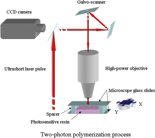
Up to now the laser systems used in TPP have mostly been Ti:Sapphire femtosecond lasers, but studies have demonstrated the feasibility of cheaper Nd:YAG microlasers Citation31. The light source is combined with computer-controlled positioning systems—e.g. piezoelectric stage or optical scanning systems—and a high-numerical-aperture immersion-oil objective is used to focus the femtosecond pulses into the photosensitive material or resin (). The charge-coupled device (CCD) camera enables real-time monitoring of the polymerization process Citation34.
Figure 9. The principle of the two-photon polymerization process. Overlap of photons from the ultrashort laser pulse leads to chemical reactions between monomers and starter molecules within the transparent matrix.
The rate of TPA is nonlinearly or quadratically dependent on incident intensity; therefore it is possible to achieve lateral resolutions better than 100 nm in the polymerized structures. Since implants, tissue engineering scaffolds, and other medical devices require features in the micrometer regime, the TPP process may offer a fast and simple way to achieve the desired resolution. Mass-produced implants and scaffolds have to be produced in several shapes and sizes; nonetheless their design does not usually take the individual patient anatomy into account. With the help of CT or other imaging methods TPP could produce scaffolds and implants with appropriate design, structure, and material properties for a particular patient. In addition, two-photon polymerization apparatus can be set up in a conventional clinical environment (e.g. an operating room) that does not need to have clean room facilities Citation35.
Potential advantages and challenges of rapid prototyping processes
Typical advantages of rapid prototyping processes are an increased speed, customization, and efficiency. RP technologies have relatively few process steps and little manual interaction; therefore three-dimensional parts can be manufactured in hours and days instead of weeks and months. The direct nature of RP allows the economic production of customized tissue engineering scaffolds. The products can be tailored to match the patient's needs and still sustain economic viability as compared to traditional techniques which must manufacture great numbers of devices to obtain economic viability. The conventional scaffold fabrication methods commonly limit the ability to form complex geometries and internal features. RP methods reduce the design constraints and enable the fabrication of desired delicate features both inside and outside the scaffold Citation36.
RP methods also make it possible to vary the composition of two or more materials across the surface, interface, or bulk of the scaffold during the manufacturing. This allows positional variations in physical properties and characteristics. Several RP techniques operate without the use of toxic organic solvents. This is a significant benefit, since incomplete removal of solvents may lead to harmful residues that affect adherence of cells, activity of incorporated biological agents, or surrounding tissues. Rapid manufacturing allows the control of scaffold porosity leading to the applications that may have areas of greater or lesser structural integrity and areas of encouraged blood flow due to increased porosity Citation36.
Although RP technologies have gained a lot of interest in the field of tissue engineering, there are some challenges that need to be addressed before these methods truly can supplant conventional fabrication methods. highlights the essential advantages and disadvantages of different RP techniques and gives the achievable print resolutions of the methods. Each RP technique requires a specific form of input material such as filament, powder or solution. The selected scaffold material must therefore be compatible with the RP process and it must be efficiently produced in the form required. Despite of numerous research studies on the optimal pore size of scaffolds, there are still contradictions about optimal pore size for particular types of cells. That of course complicates the manufacturing of ideal scaffolds, although with regard to rapid manufacturing it would be possible to make structures with desired pore size. The surface roughness of scaffolds is a very important factor influencing the cell-matrix interactions. Powder-based techniques produce rough surfaces that may enhance cell adhesion. Some RP systems, such as FDM and 3D Bioplotter®, generate smooth surfaces that cannot ensure optimal cell adhesion. Therefore these smooth surfaces require further surface modification or coating Citation4, Citation37.
Table I. Comparison of different rapid prototyping (RP) methods on the basis of their achievable resolution, advantages, and disadvantages.
The feasibility of scaffold fabrication by RP processes also depends on the resolution of the machines. Resolution in this context refers to the smallest pores and thinnest material structures that are obtainable with the equipment. The resolution is a consequence of several machine-specific parameters, the overall working principle of the machine, geometry-specific parameters, and material properties. The smallest feature size is mediated by the laser spot size or the nozzle diameter. Even the powder size affects the features produced by powder-based RP methods. Laser curing processes have much better resolution than droplet-based systems. Some limitations to RP processes are caused by materials trapped in small internal holes. These trapped liquid or loose powder materials may be difficult or even impossible to remove afterwards, and in some cases these residues may even be harmful to cells and tissues. Experimental results show that the smoother the surface generated, the easier the removal of trapped materials Citation37. Many of the current RP processes rely on high temperatures during and after manufacture. These elevated temperatures may be harmful to several biomaterials and are not suitable for cell processing. Also little attention has been paid to the sterility of the manufacturing process and products and their ability to withstand sterilization processes which are crucial steps in transferring technologies to commercial production Citation36.
Future directions
As reviewed, each RP process has its own unique advantages and disadvantages in producing tissue engineering scaffolds. Most likely in the future research will further embrace the development of RP machines designed specifically for this application. Nevertheless, RP techniques already offer an efficient way to control the design, fabrication, and modeling of the scaffold being constructed. Especially three-dimensional printing, selective laser sintering, and fused deposition modeling have been studied intensively for use in scaffold-based tissue engineering. However, there are still many hurdles for these technologies to overcome to gain status as everyday manufacturing methods instead of traditional techniques.
The biggest obstacles for RP technologies are the restrictions set by material selection and aspects concerning the design of the scaffold's inner architecture. Thus, any future development in the RP field should be based on these biomaterial requirements, and it should concentrate on the design of new materials and optimal scaffold design. In order to achieve scaffolds that are optimal for regeneration of specific tissues, the scientists must first attain answers to some critical questions concerning issues like what is the perfect scaffold material, or does increased permeability of the material really enhance tissue regeneration.
Current RP methods can manufacture features at scales larger than 100 µm, but sooner or later in the future it will be possible to achieve features in micro- and nanometer scale. Currently micrometer size details can be gained mainly through postprocessing steps. The advantages of adding very fine details into scaffolds include improvement of mechanical properties through toughening mechanisms and better cell adhesion, and guidance of the cell growth along the surface. The ultimate scaffold will probably be constructed of computationally optimized 3D architecture with added biofunctional factors, where the material and functionalizing factors will be fabricated simultaneously. Hydrogel materials and different extrusion methods are suitable for fabricating functionally active scaffolds, but unfortunately these structures do not always possess high enough mechanical strength to be utilized in reconstruction of hard tissue and most soft tissues. Nevertheless, future efforts will hopefully result in designer tissue replacements created from patient-derived data and fabricated of multiple materials, cells, genes, and proteins optimized specifically for tissue regeneration.
So far, only a few research groups have demonstrated the exploitation of RP technologies in clinical applications. Within the bone tissue engineering field at least selective laser sintering has proven its usefulness to fabricate polycaprolactone scaffolds. These scaffolds were seeded with primary human gingival fibroblasts (HGF) and implanted subcutaneously in mice to evaluate biological properties and to demonstrate tissue in-growth. In order to provide a proof of concept, SLS was also utilized to manufacture anatomically shaped minipig's mandibular condyle scaffold that can be attached to the mandibular ramus via a designed collar. Also 3D printing has been used to create negative molds into which a polylactide solution can be poured and thermally phase-separated to create nanofibrous scaffolds. These 3D fibrous matrices were seeded with mouse preosteoblasts and cultures for 12 days in order to examine the cellular response to the scaffold surface Citation17, Citation44–46.
The research has not yet proceeded into actual clinical studies, only some cell culture and animal experiments have been conducted, for example with minipigs, rabbits, and mice. Osteogenesis has been studied by implanting scaffolds intramuscularly into animals and by adding growth factors to induce bone formation in the muscle. The results of all these studies show that microporosity and very fine surface features improve bone growth into scaffolds by increasing surface area for protein adsorption, increasing ionic solubility in the microenvironment, and providing attachment points for osteoblasts Citation17, Citation44–46.
The RP approaches have not yet led to the construction of harmonically organized complex tissues. This is probably due to the difficulty of embedding the various cell types within the intricate designs. However, organ printing may be an answer to the problem, since it can print simultaneously cells and biomaterials, which allows precise placements of cells and proteins within 3D hydrogel structures. A number of structures have already been printed with the setup, including tubes, branched tubes, hollow cones, and capillaries. Cell types used include Chinese hamster ovary cells, endothelial cells, smooth muscle cells, osteoblasts, and stem cells. Preliminary data suggest that many layers of cells and hydrogels can be printed into 3D structures using a fast gelling hydrogel system and that cells remain viable in constructs as thick as 1 cm due to the programmed porosity. Thus organ printing has the potential to revolutionize the field of cardiothoracic surgery by offering contractile pseudo-tissues, such as myocardium or vascular conduits. However, considerable improvements in the biomaterials used as bioinks and papers must be made before any clinical applications can be obtained Citation28, Citation47.
References
- Burg KJL, Boland T. Minimally invasive tissue engineering composites and cell printing. IEEE Eng Med Biol Mag. 2003; 22: 84–91
- Landers R, Pfister A, Hübner U, John H, Schmelzeisen R, Mülhaupt R. Fabrication of soft tissue engineering scaffolds by means of rapid prototyping techniques. J Mater Sci. 2002; 37: 3107–16
- Sachlos E, Czernuszka JT. Making tissue engineering scaffolds work. Review on the application of solid freeform fabrication technology to the production of tissue engineering scaffolds. Eur Cell Mater. 2003; 5: 29–40
- Yeong W-Y, Chua C-K, Leong K-F, Chandrasekaran M. Rapid prototyping in tissue engineering: challenges and potential. Trends Biotechnol. 2004; 22: 643–52
- Hutmacher DW, Cool S. Concepts of scaffold-based tissue engineering—the rationale to use solid free-form fabrication techniques. J Cell Mol Med. 2007; 11: 654–69
- Hutmacher DW, Sittinger M, Risbud MV. Scaffold-based tissue engineering: rationale for computer-aided design and solid free-form fabrication systems. Trends Biotechnol. 2004; 22: 354–62
- Webb PA. A review of rapid prototyping (RP) techniques in the medical and biomedical sector. J Med Eng Technol. 2000; 24: 149–53
- Hieu LC, Zlatov N, Vander Sloten J, Bohez E, Khanh L, Binh PH, et al. Medical rapid prototyping applications and methods. Assembly Automation. 2005; 25: 284–92
- Truscott M, de Beer D, Vicatos G, Hosking K, Barnard L, Booysen G, et al. Using RP to promote collaborative design of customised medical implants. J Rapid Prototyping. 2007; 13: 107–14
- Lee K-W, Wang S, Fox BC, Ritman EL, Yaszemski MJ, Lu L. Poly(propylene fumarate) bone tissue engineering scaffold fabrication using stereolithography: Effects of resin formulations and laser parameters. Biomacromolecules. 2007; 8: 1077–84
- Kalita SJ, Bose S, Hosick HL, Bandyopadhyay A. Development of controlled porosity polymer-ceramic composite scaffolds via fused deposition modeling. Mater Sci Eng C. 2003; 23: 611–20
- Liu X, Ma PX. Polymeric scaffolds for bone tissue engineering. Ann Biomed Eng. 2004; 32: 477–86
- Saiz E, Gremillard L, Menendez G, Miranda P, Gryn K, Tomsia AP. Preparation of porous hydroxyapatite scaffolds. Mater Sci Eng C. 2007; 27: 546–50
- Melchels FPW, Villagomez M, Lacroix D, Planell JA, Grijpma DW, Feijen J. Designed tissue engineering scaffolds prepared by stereolithography. Proceedings of the 21st European Conference on Biomaterials; 2007 Sep 09–12; Brighton, UK. In press 2007.
- Leukers B, Gülkan H, Irsen SH, Milz S, Tille C, Schieker M, et al. Hydroxyapatite scaffolds for bone tissue engineering made by 3D printing. J Mater Sci Mater Med. 2005; 16: 1121–4
- Khalyfa A, Vogt S, Weisser J, Grimm G, Rechtenbach A, Meyer W, et al. Development of a new calcium phosphate powder-binder system for the 3D printing of patient specific implants. J Mater Sci Mater Med. 2007; 18: 909–16
- Williams JM, Adewunmi A, Schek RM, Flanagan CL, Krebsbach PH, Feinberg SE, et al. Bone tissue engineering using polycaprolactone scaffolds fabricated via selective laser sintering. Biomaterials. 2005; 26: 4817–27
- Partee B, Hollister SJ, Das S. Selective laser sintering process optimization for layered manufacturing of CAPA® 6501 polycaprolactone bone tissue engineering scaffolds. Transact ASME: J Manufacturing Sci Eng. 2006; 128: 531–40
- Tan LL. Plugging bone the painless way. Innovation 2004; 4
- Hutmacher DW. Scaffolds in tissue engineering bone and cartilage. Biomaterials. 2000; 21: 2529–43
- Tellis BC, Szivek JA, Bliss CL, Margolis DS, Vaidyanathan RK, Calvert P. Trabecular scaffolds created using micro CT guided fused deposition modeling. Mater Sci Eng C. 2007; 81B: 30–9
- Landers R, Hübner U, Schmelzeisen R, Mülhaupt R. Rapid prototyping of scaffolds derived from thermoreversible hydrogels and tailored for applications in tissue engineering. Biomaterials. 2002; 23: 4437–47
- Yousefi A-M, Gauvin C, Sun L, DiRaddo RW, Fernandes J. Design and fabrication of 3D-plotted polymeric scaffolds in functional tissue engineering. Polym Eng Sci. 2007; 47: 608–18
- Pfister A, Landers R, Laib A, Hübner U, Schmelzeisen R, Mülhaupt R. Biofunctional rapid prototyping for tissue-engineering applications: 3D Bioplotting versus 3D Printing. J Pol Sci: Part A: Pol Chem. 2004; 42: 624–38
- Landers R, Mülhaupt R, John H. Desktop manufacturing and biofunctional processing, new applications in tissue engineering. Kunststoffe. 2001; 91: 58–60
- Boland T, Mironov V, Gutowska A, Roth EA, Markwald RR. Cell and organ printing 2: fusion of cell aggregates in three dimensional gels. Anat Rec A Discov Mol Cell Evol Biol. 2003; 272A: 497–502
- Mironov V, Boland T, Trusk T, Forgacs G, Markwald RR. Organ printing: computer-aided jet-based 3D tissue engineering. Trends Biotechnol. 2003; 21: 157–61
- Boland T, Tao X, Damon BJ, Manley B, Kesari P, Jalota S, et al. Drop-on-demand printing of cells and materials for designer tissue constructs. Mater Sci Eng C. 2007; 27: 372–6
- Jakab K, Neagu A, Mironov V, Forgacs G. Organ printing: fiction or science. Biorheology. 2004; 41: 371–5
- Mironov V, Markwald RR, Forgacs G. Organ printing: self-assembling cell aggregates as ‘bioink’. Sci Med. 2003; 9: 69–71
- Farsari M, Filippidis G, Sambani K, Drakakis TS, Fotakis C. Two-photon polymerization of an Eosin Y-sensitized acrylate composite. J Photochem Photobiol A. 2006; 181: 132–5
- Postnikova BJ, Currie J, Doyle T, Hanes RE, Anslyn EV, Shear JB, et al. Toward nanoscale three-dimensional fabrication using two-photon initiated polymerization and near-field excitation. Microel Eng. 2003; 69: 459–65
- Wu S, Serbin J, Gu M. Two-photon polymerisation for three-dimensional micro-fabrication. J Photochem Photobiol A. 2006; 181: 1–11
- Ostendorf A, Chickov BN. Two-photon polymerization: a new approach to micromachining. Photon Spectra. 2006; Oct:72–80.
- Ovsianikov A, Chichkov B, Adunka O, Pillsbury H, Doraiswamy A, Narayan RJ. Rapid prototyping of ossicular replacement prostheses. Appl Surf Sci. 2007; 253: 6603–7
- Savalani MM, Harris RA. Layer manufacturing for in vivo devices. Proc Inst Mech Eng [H] 2006; 220: 505–20
- Yang S, Leong K-F, Du Z, Chua C-K. The Design of Scaffolds for Use in Tissue Engineering. Part II. Rapid Prototyping Techniques. Tissue Eng. 2002; 8: 1–11
- Lam CXF, Mo XM, Teoh SH, Hutmacher DW. Scaffold development using 3D printing with a starch-based polymer. Mater Sci Eng C. 2002; 20: 49–56
- Tan KH, Chua CK, Leong KF, Cheah CM, Cheang P, Abu Bakar MS, et al. Scaffold development using selective laser sintering of polyetheretherketone-hydroxyapatite biocomposite blends. Biomaterials. 2003; 24: 3115–23
- Zein I, Hutmacher DW, Tan KC, Teoh SH. Fused deposition modeling of novel scaffold architectures for tissue engineering applications. Biomaterials. 2002; 23: 1169–85
- Landers R, Mülhaupt R. Desktop manufacturing of complex objects, prototypes and biomedical scaffolds by means of computer-assisted design combined with computer-guided 3D plotting of polymers and reactive oligomers. Macromol Mater Eng. 2000; 282: 17–21
- Roth A, Xu T, Das M, Gregory C, Hickman JJ, Boland T. Inkjet printing for high-throughput cell patterning. Biomaterials. 2004; 25: 3707–15
- Wohlers T. Rapid prototyping and tooling state of the industry annual worldwide progress report. Wohlers Report 2000. Wohlers Associates, Inc, Fort Collins, CO 2000
- Chen VJ, Smith LA, Ma PX. Bone regeneration on computer-designed nano-fibrous scaffolds. Biomaterials. 2006; 27: 3973–9
- Woodard JR, Hilldore AJ, Lan SK, Park CJ, Morgan AW, Eurell JAC, et al. The mechanical properties and osteoconductivity of hydroxyapatite bone scaffolds with multi-scale porosity. Biomaterials. 2007; 28: 45–54
- Pang L, Hu Y, Yan Y, Liu L, Xiong Z, Wei Y, et al. Surface modification of PLGA/(-TCP scaffold for bone tissue engineering: Hybridization with collagen and apatite. Surf Coat Technol. 2007; 201: 9549–57
- Varghese D, Deshpande M, Xu T, Kesari P, Ohri S, Boland T. Advances in tissue engineering: Cell printing. J Thorac Cardiovasc Surg. 2005; 129: 470–2