Abstract
Results of coupled mechanical and fluid-flow modelling provide insights into some of the factors that controlled gold mineralisation and deformation in the Hodgkinson Province in northeastern Queensland. These results aid in resolving why the north – south-striking segment of the terrane-bounding Palmerville Fault is barren, while many north – south- to northwest – southeast-trending, second-order fault zones throughout the Hodgkinson Province are spatially associated with gold deposits. The simplified, regional-scale model geometry used in this study permitted variation of boundary conditions, material properties and stress regimes. This included variation of lithological properties, the absence of fault zones in some models, and the application of plane strain or transpression. The model outcomes illustrate the importance of a listric fault geometry for focusing deformation and fluid flow in zones of relatively high permeability and/or low rock strength. Also, the orientation of fault zones with respect to the dominant far-field compressive stress regime is shown to be a key factor controlling deformation and fluid flow. In addition, fault bends and terminations are shown to influence significantly the distribution of deformation and fluid flow in our models. The results provide an improved understanding of first-order factors that may have controlled localisation of deformation and fluid flow in the regional geological architecture of the Hodgkinson Province. Focused fluid flow arising from localised dilation and permeability increase plays an important role in the formation of ore deposits; hence the outputs of the modelling may be of significant value for future exploration in the Hodgkinson Province and analogous regions elsewhere. The study illustrates the usefulness of numerical modelling as a tool for testing multiple scenarios, leading to improved conceptual understanding of geological systems.
Introduction
Major fault systems that penetrate deep into the crust can provide pathways and foci for both mineralising fluids and magmatism in the upper crust (Groves et al.Citation1998; Sillitoe Citation2000; Cox et al.Citation2001). The >200 km long, north- to northwest-striking Palmerville Fault is such a major structure in northeastern Australia, delineating the boundary between the Palaeozoic Hodgkinson Province and Proterozoic assemblages to the west ( ). No mineral occurrences have been recognised along the north-striking section of the Palmerville Fault. From the point where the strike of the Palmerville Fault changes from north to northwest, granites and volcanic rocks intrude the fault system. These rocks formed during Carboniferous to Permian magmatism and host several significant gold – copper and skarn deposits (e.g. Red Dome and Mungana deposits: Nethery & Barr Citation1998). A number of north- to northwest-striking faults that are subparallel to the Palmerville Fault traverse the Hodgkinson Province and are associated with occurrences of orogenic-gold mineralisation (Peters et al.Citation1990; Garrad & Bultitude Citation1999).
Figure 1 General geology of the Hodgkinson Province. The Palmerville Fault forms the bounding structure at the western margin of the province that accommodated major basin extension and inversion during the Palaeozoic (Vos et al. in press).
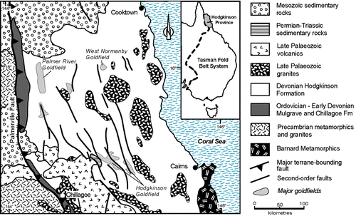
To overcome limitations imposed by restricted exposure and relatively low data density in the Hodgkinson Province, Vos et al. (in press) have integrated structural mapping, potential-field analysis, and forward modelling of magnetic and gravity data to gain insight into the nature of the Palmerville Fault and its role in the tectonic evolution of the province. Results from this multidisciplinary study suggest that the Palmerville Fault represents an eastward-dipping, listric and inverted normal fault that controlled opening of the Hodgkinson Basin in the Ordovician to Devonian. During subsequent basin inversion in the Devonian to Carboniferous, the Palmerville Fault was reactivated, and orogenic-gold deposits formed along secondary faults that are subparallel to the Palmerville Fault (Vos & Bierlein Citation2006). Insights into the geometry and structure of the Hodgkinson Province allow for an improved analysis of processes that controlled gold mineralisation in the region.
Coupled mechanical and fluid-flow numerical simulations were carried out to investigate factors that may have controlled gold mineralisation in the western part of the Hodgkinson Province. In particular, the role of the Palmerville Fault in controlling deformation and fluid flow was assessed. A number of model scenarios were set up to provide an insight into the loci of dilation, anomalous fluid flow and shear strain under varying deformation conditions with different model geometries and parameter values. Key results from our modelling are compared with the geology of the Hodgkinson Province. Specifically, we investigate deformation and fluid-flow characteristics along segments of the Palmerville Fault with different strike orientation, and around bends and terminations of second-order faults. Ultimately, we aim to investigate the factors that controlled gold mineralisation along first- and second-order faults in the Hodgkinson Province (as indicated on ) and resolve why the terrane-bounding Palmerville Fault remained largely barren. Although we have used the geology of the Hodgkinson Province as a template for the set-up of our numerical model, the work reported provides important implications for understanding the connection between fluid flow, deformation and gold mineralisation in similar settings elsewhere.
Geological background
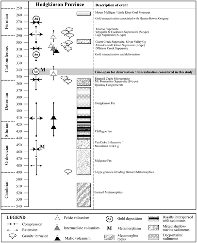
Bultitude et al. (Citation1997) and Vos et al. (Citation2006) have summarised the Palaeozoic structural history of the Hodgkinson Province. In brief, basin formation during the Late Ordovician to Devonian resulted in the deposition of three lithological units that make up the majority of the province: (i) arenites of the Upper Ordovician Mulgrave Formation along the western edge of the province; (ii) limestones and basalts of the Chillagoe Formation juxtaposed to the east of the Mulgrave Formation; and (iii) sandstones and siltstones of the Hodgkinson Formation covering the remainder of the province ( ). Following Silurian and Devonian basin formation and infill, the Hodgkinson Province was affected by at least four deformation phases in the Late Devonian and Carboniferous. These deformation phases resulted in the generation of a series of mainly north- to northwest-trending overprinting structures ranging from early isoclinal folds and mélange zones to later more open, steeply plunging folds and reverse faults. The Late Carboniferous and Permian mark an episode of magmatism in the Hodgkinson Province (Bultitude et al. Citation1997). The spatial relationship of orogenic-gold deposits to secondary faults that are subparallel to the Palmerville Fault has been demonstrated by Peters et al. (Citation1990), Vos et al. (Citation2004) and Vos and Bierlein (Citation2006), who all indicated that these deposits formed from low-salinity homogeneous fluids at mid- to upper crustal levels (∼5 – 10 km). Furthermore, Vos and Bierlein (Citation2006) demonstrated that at least two episodes of orogenic-gold mineralisation occurred during the Late Devonian to Carboniferous, and were related to east – west contraction and subsequent transpression associated with reverse and strike-slip movement along secondary fault structures. An overview of the main tectonic, metallogenic, magmatic and sedimentary events is provided in .
Figure 2 Overview of the Palaeozoic geological evolution of the Hodgkinson Province, including tectonic, metallogenic, magmatic and sedimentary events, indicating the time frame considered for modelling in this study (after Vos & Bierlein Citation2006).
Flac3D numerical modelling
In this study, we have used the three-dimensional Lagrangian finite-difference code FLAC3D (Cundall & Board Citation1988; Itasca Citation2002) to simulate the coupling of fluid flow and deformation. In FLAC3D, crustal-scale processes can be simulated by modelling regionally significant faults and shear zones as zones of different (weaker) material properties in the finite-difference grid (Sorjonen-Ward et al. Citation2002). Numerical simulations in FLAC3D are defined in terms of: (i) the model architecture; (ii) the material properties assigned to the mesh elements; and (iii) the boundary conditions considered most relevant to the purpose of modelling. Each of these attributes can be varied systematically to test their effects on deformation and fluid flow in the model architecture. Results can be compared and used to resolve basic geological questions, such as the effect of a listric fault geometry compared to a planar fault geometry. An extensive overview of coupled modelling of deformation and fluid flow with FLAC is given by Oliver et al. (Citation2001) and Sorjonen-Ward et al. (Citation2002) from which we have summarised the important characteristics.
The Mohr – Coulomb elastic – plastic constitutive model is used to simulate brittle frictional behaviour (Vermeer & de Borst Citation1984). This constitutive model predicts dilation during shear failure, representing the effect of grains sliding over one another (see Ord & Oliver Citation1997 for further discussion).
Fluid flow in FLAC3D is governed by Darcy's Law and hence is controlled by variations in hydraulic head and permeability.
Deformation and fluid flow are coupled in FLAC3D through: (i) the effect of volume change on fluid pressure (dilation results in a reduction in fluid pressure, compaction results in an increase in fluid pressure); and (ii) the impact of fluid pressure on effective stress (increasing fluid pressure results in a decrease in effective normal stress, bringing the rock closer to failure). Further feedback between deformation and fluid flow can be introduced by allowing permeability to vary with shear or volumetric strain, and/or with failure state (elastic/plastic: Ord Citation1991; Ord & Oliver Citation1997).
Our models use isotropic permeability for each mesh element (i.e. each element is equally permeable in all directions). However, permeability can become anisotropic at the scale of the model if failure is localised along lines or planes of interconnected cells (e.g. a fault).
Fluid flow in FLAC3D can be driven by changes in fluid pressure due to localised dilatancy or compaction and/or by regional gradients in hydraulic head, which may be imposed by specifying a fixed, elevated fluid pressure or fixed fluid flux on all or part of the model boundary. The latter could represent connectivity of the modelled region with an overpressured fluid reservoir at depth. Dilation typically results in local perturbations to a regional flow field. Both scenarios are investigated in this study.
Porosity in FLAC3D is usually kept constant and has no relationship with permeability. Changing porosity has only a minor effect on fluid flow (specifically, it changes the length scale of flow); changes in permeability are much more important for fluid flow. However, FLAC3D does account for the effect of volumetric strain on fluid pressure (i.e. compaction causes fluid pressure to increase, dilation causes fluid pressure to decrease).
Mohr – Coulomb behaviour is independent of strain rate; thus the number of model steps simulated is not directly related to the duration of a deformation event (the mechanical time-step is a non-dimensional number). However, the fluid-flow time-step is an absolute time-value, and because fluid flow is coupled with mechanical deformation, we can derive the mechanical time-step as an absolute value and thus calculate the strain rate in our models.
Episodic slip is a common feature of fault behaviour in the brittle upper crust (Cox et al. Citation2001). Such behaviour is difficult to reproduce in FLAC3D, although Ord et al. (Citation2004) have made progress in this direction by incorporating rate- and state-dependent friction laws into the continuum formulation. When a mesh element fails in FLAC3D, it generally remains in a state of failure (i.e. the stress state remains on the yield envelope) until the stress regime is changed. This continuous failure mode may be thought of as a time-averaged approximation of multiple, discrete slip events, or aseismic creep. Episodic behaviour can arise in FLAC3D as a consequence of the interplay between permeability, fluid pressure and effective stress. This effect is discussed in more detail in the results section.
Mechanical and fluid-flow modelling of the western Hodgkinson Province
Model geometry
We have constructed a FLAC3D model that represents a block of crust 50 km wide, 50 km long and 5 km deep. The dimensions, orientation and geometry of the model represent the simplified geology of the western Hodgkinson Province ( ), constrained by integrated geological, geophysical and geochemical datasets (Vos et al. in press). The length axis (i.e. y direction) of the model is orientated north – south, parallel to the simulated northern segment of the Palmerville Fault. The upper surface of the model is subject to pressures representing 12.5 km of overburden. This is based on lower greenschist facies metamorphic conditions that occurred throughout the Hodgkinson Province (Peters et al. Citation1990; Garrad & Bultitude Citation1999; Vos et al. Citation2004), which imply the removal of approximately this thickness of overburden by erosion. The model geometry comprises four crustal blocks separated by faults (), with the westernmost block representing crystalline basement exposed in the footwall of the Palmerville Fault, and the remaining blocks representing two or three lithological domains with different rock properties. Some models were run without faults (that is, the faults were assigned the same properties as the adjacent blocks), and others were run with the easternmost fault terminating within the model. Vos et al. (in press) demonstrated that the terrane-bounding Palmerville Fault is a steeply east-dipping structure that becomes listric at depth, where it acted as a décollement zone that accommodated basin inversion in the Hodgkinson Province during the Late Palaeozoic. Our models use either a planar or listric geometry for the Palmerville Fault (i.e. the westernmost fault in the model), although it should be emphasised that we have not attempted to represent flattening into a décollement zone due to limitations with mesh construction.
Figure 3 Overall model architecture representing a block of crust 50 km wide, 50 km long and 5 km deep. (a) Base architecture with two lithologies and three through-going faults showing the model setup in plan view (top) and cross-section (bottom). (b) Variations on the base architecture with three lithologies and no faults (top) and three lithologies, two through-going faults and a fault segment covering half the blocks length (bottom).
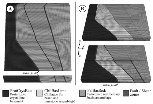
The number of faults, lithologies and initial pore pressures were varied in order to identify the factors that may have controlled deformation and fluid-flow patterns in the Hodgkinson Province. An overview of constructed model architectures, where the number of faults, lithologies and initial pore-pressure conditions were varied, is given in , and three examples of model geometries are shown in .
Table 1 Overview of model architectures, with varying number of faults, lithologies and pore pressure.
Material properties and boundary conditions
We have used the Mohr – Coulomb elastic – plastic constitutive model for our FLAC3D simulations, which means that the rock deforms in an elastic manner until it reaches a yield point, after which plastic deformation occurs. The material properties used in our models are presented in . These values represent rock properties in the Hodgkinson Province and are based on published data for the modelled rock types (Turcotte & Schubert Citation1982). Faults are treated as zones of weakness, with mesh elements in the faults having lower cohesion and friction angles than those in the wall-rocks. Some models were run without faults (i.e. the faults were assigned the same properties as the surrounding wall-rocks) to determine whether lithological contacts would act as preferential sites for dilation and shear strain (e.g. model setup 5, ).
Table 2 Rock properties for lithologies used in model setups.
Boundary conditions in numerical models commonly give rise to boundary effects manifested as stress, strain and fluid-flow anomalies. Such anomalies may, for instance, develop where mesh orientation is poorly aligned with respect to model boundaries, or at impermeable surfaces in the model geometry. To counteract these effects, a bounding box was created that acts as a buffer zone between the applied boundary conditions and the model itself, such that most anomalies occur within this buffer zone, rather than in the main part of the model. The properties of a sedimentary assemblage (i.e. relatively permeable and structurally weak, see PalBasSed) were assigned to the bounding box. However, where faults exist in the model architecture, these were continued into the bounding box, and the properties of a fault () were assigned to the relevant cells. The dimensions of the bounding box and its relationship to the actual model architecture (internal model box) are illustrated in , and the effects of the bounding box on the pore pressure distribution in the model are illustrated in . The internal box is permeable along all sides, allowing fluid to move between the internal and external boxes. The external box is impermeable on all sides, except where a fluid influx is applied along the bottom of the box (see below). These boundary conditions allow fluids to flow in and out of the internal box, while at the same time high pore-fluid pressures can be maintained, because the outer surface of the external box acts as a seal.
Figure 4 (a) Extent of bounding box (buffer zone) surrounding the model architecture (internal model box) to minimise boundary effects that may result from boundary conditions as discussed in text. This bounding box allows fluids to flow through the internal box (which represents the region of interest) without actually flowing out of the entire model. Note that the first 5 km of the external bounding box have been made transparent, so the start of the internal model box is visible, surrounded by the buffer zone on both sides and along the top. (b) Schematic pore-pressure vs depth diagram: Line A represents one of the two initial (prior to model equilibration) pore pressure conditions imposed upon the models (0.5×lithostatic pore fluid pressure). Curve 1 indicates the post-equilibration fluid-pressure conditions where the pore pressure has equilibrated to a hydrostatic gradient, but at supra-hydrostatic pressures. Curve 2 is indicative of pore pressures after injection of fluids at the base of the model (in those models which incorporate fluid injection).
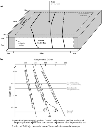
The models are initialised with pore-fluid pressure equal to some fraction of lithostatic pressure (generally 0.5: ), and are then allowed to equilibrate before deformation is applied. The fluid pressure evolves to establish an internal hydrostatic gradient at supra-hydrostatic pressures during this equilibration phase ( curve 1), such that the fluid flux is zero throughout the model at the start of deformation. The absolute value of fluid pressure remains above hydrostatic because the entire model box is sealed on all sides.
Some of our models had fluid injected into specified regions along the base of the model (e.g. a particular lithology or fault zone: ). This set of models included fluid injection into faults or into the sedimentary unit, representing fluids coming from overpressured reservoirs at depth, or from regional metamorphic devolatilisation. Curve 2 in illustrates the effect of fluid injection on the fluid-pressure gradient.
Table 3 Modes of deformation used in model runs.
It should be noted that our choice of impermeable boundaries for the external model box (with the exception of fluid injection on the lower boundary in some models) is one of several possible and geologically reasonable boundary conditions. Our justification for this boundary condition (specifically the impermeable top boundary) is that fluid pressures are likely to be supra-hydrostatic at the modelled depths, which requires either a continuous flux of fluid into the base of the model or a seal at the top of the model. If the top boundary were not sealed, fluid pressure would relax to hydrostatic in the absence of a fluid flux into the base of the model, which would be unrealistic at such depths. We acknowledge that our results would be likely to change with different boundary conditions, and exploration of the effect of different boundary conditions would be an interesting avenue for further investigation.
All models are subject to the following mechanical boundary conditions: (i) the top boundary is free to move in all directions, and is subject to an applied normal stress representing 12.5 km of overburden (depth×gravity×density); (ii) the base of model is free to slide in the horizontal plane, but no vertical movement is allowed; and (iii) vertical boundaries move with fixed velocity to produce east – west-shortening (plane strain), or east – west- shortening with a component of sinistral strike-slip (transpression). Condition (i) allows the development of topography on the top surface of the model. Note that condition (ii) means that topographic elevation and lateral variations in density are not compensated for isostasy. All models commenced with an initial phase of stress balancing to obtain mechanical equilibrium under gravity prior to the application of boundary velocities. Tectonic deformation was simulated by applying velocity fields to the vertical boundaries (condition iii), generating strain rates in the order of 10−13/s. This rather high strain rate is probably at least 10 times faster than typical tectonic strain rates, but is required in order to reach sufficiently large total strain to observe the behaviour of interest in FLAC3D within a reasonable time frame (i.e. days rather than months). However, it should be emphasised that the mechanical formulation itself is not time-dependent; it is only the coupling with fluid flow that necessitates consideration of time.
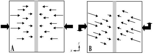
Boundary velocities (condition iii) were chosen to simulate the interpreted tectonic regime at the time of gold mineralisation in the Hodgkinson Province (in accordance with the deformation regime during the Late Devonian – Early Carboniferous: ). Shortening in an east – west direction (plane strain: ), and shortening with a sinistral component of strike-slip (transpression: ) are considered to reflect the most likely principal shortening directions associated with successive stages of mineralisation in the Hodgkinson Province in the Late Devonian – Early Carboniferous and Late Carboniferous, respectively (Peters et al. Citation1990; Vos et al. Citation2004). The latter episode of deformation coincided with a period of regional magmatism that included intrusion of magmas along the northwest-trending segment of the Palmerville Fault ().
Figure 5 Model deformation conditions (plan view). (a) Plane strain: model is subject to 10% shortening along the x-axis. (b) Transpression: model is subject to 5% sinistral strike-slip deformation along the z-axis, in addition to 10% shortening along the x-axis. External (fat) arrows indicate relative magnitudes of x and z velocities applied to model boundaries; internal (finer) arrows indicate the magnitude and direction of forces working on the cell mesh. The grey-shaded area indicates central focus area towards which deformation forces are directed.
Some models included a rule to increase permeability at failure, simulating the effect of shear and tensile failure on permeability. In these scenarios, the permeability of a mesh cell varies with failure state (e.g. deformation modes 3 and 4: ), such that when a model cell fails in tension or shear, permeability of that cell is increased by a factor of 50 or 10, respectively. These values are intended to represent the difference in permeability between an (open) tensile crack and a shear fabric network on the scale of each model cell. In all our models, fault zones have been assigned higher initial permeabilities than adjacent rocks.
All models were shortened by up to 10%, which was approximately the maximum shortening value our model geometries could sustain before becoming unstable due to deficiencies in the finite difference mesh. Such deficiencies commonly limit the outcome of FLAC models when dealing with more extreme deformation and shortening. We recognise that crustal shortening in the Hodgkinson Province may have been substantially greater to generate orogenic-gold deposits. Nevertheless, we argue that first-order fluid and deformation effects, which may be enhanced with increasing degrees of deformation, can still be recognised in our models. A summary of the deformation modes and boundary conditions applied to our models is presented in .
Modelling results and interpretations
Results and interpretation of key outcomes of our modelling work are presented as a series of illustrations generated with FracSIS software (Fractal Technologies Citation2004) for selected model scenarios that are defined in , and . Since not all model runs were completed to 10%, we show results after 9% of shortening, which was the maximum amount of deformation obtained for all of the selected models. An overview of all model runs is given in . Figures showing the distribution of shear and volumetric strain ( , ) were created by applying a cutoff (lower limit) to the range of values shown, in order to emphasise the distribution of high strain regions in 3D. For example, the legend for shows values ranging from 0.0 to 3.2, but only values >0.15 are shown in the figure. A similar cutoff technique was used to create the images of fluid flow vectors, where the colour of each arrow represents the magnitude of the fluid flux.
Table 4 Overview of completed model runs indicating model setup (see ) and deformation modes used (see ).
Figure 6 3D representation of cumulative shear-strain distribution after 9% shortening: (a) plane strain, listric fault (Model Run 1); (b) transpression, listric fault (Model Run 2); (c) plane strain, planar fault (Model Run 1); (d) transpression, planar fault (Model Run 2). Model run numbers relate to .
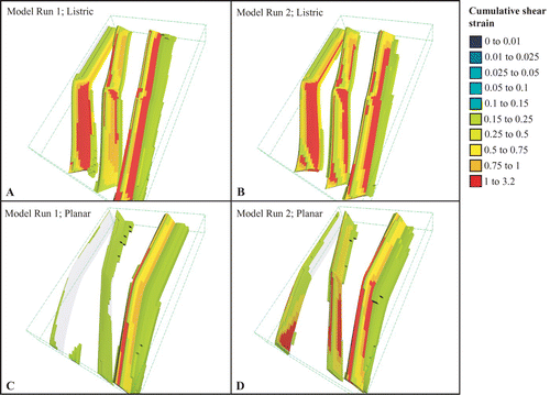
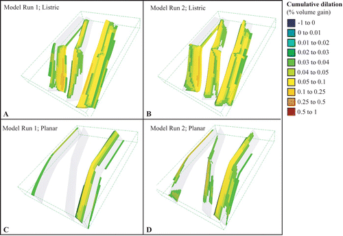
Figure 7 3D representation of cumulative distribution of dilation (percentage volume increase) after 9% shortening: (a) plane strain, listric fault (Model 1); (b) transpression, listric fault (Model 2); (c) plane strain, planar fault (Model 1); (d) transpression, planar fault (Model 2). Model run numbers relate to . Negative values indicate percentage volume loss/compaction.
Listric versus planar fault
In order to understand the effect of fault geometry on deformation and fluid flow, we initially compared a planar to a listric fault scenario. Here, we present results of model runs 1 and 2 ( ) for both a listric and planar fault geometry. and illustrate the distribution of cumulative shear strain and dilation, respectively, after 9% shortening in each case. Since dilation provides the driving force for fluid flow in our models, fluid-flow and dilation diagrams would show a similar distribution. We have chosen to show results for dilation for the scenarios discussed here only, because we found that these were more representative than fluid-flow diagrams (which are shown for all other model scenarios).
Shear strain and dilation
In all models, mesh elements in the faults are weaker (lower cohesion and friction angle: ) than those in the wall-rocks; hence it is expected that the highest values of shear strain and dilation will occur in the faults, simulating slip along the faults while the wall-rocks remain relatively undeformed. This is confirmed in the listric fault scenario ( , ), where shear strain and dilation are partitioned into all three faults and the immediately surrounding wall-rocks, although less so in the northern segment of the listric fault. High values of shear strain and dilation are associated with the southern segment of the listric fault, especially towards the base of the model (i.e. the listric portion). Fault bends are also sites of relatively high shear strain and dilation. In the planar fault scenario (, ), shear and volume strain are partitioned mainly into the easternmost fault, with the central and western faults showing much smaller values of shear strain and dilation than in the listric fault scenario. Transpression results in slightly greater shear and volume strain in the central and western faults (, ), particularly along the southern fault segments that are non-perpendicular to the principal shortening direction.
Interpretation
Our results suggest that the shape of the westernmost fault (planar or listric) affects the partitioning of shear strain and dilation between all faults in the model. In the planar fault model, shear strain was focused dominantly along the easternmost fault, whereas the listric fault geometry resulted in a more even distribution of strain along all faults. The most likely explanation for this is that the listric fault has a shallower average dip than the planar fault, and hence is more favourably oriented for reverse slip, and therefore allows perturbation of strain throughout the model. Shear strain is generally higher around fault bends, and the distribution of shear strain and dilation is influenced by the strike orientation of faults with respect to the maximum principal stress.
Variations in pore-fluid pressure, lithological properties and permeability
The initial pore-fluid pressure, lithological properties, and permeability were varied for several model runs to investigate the impact of these factors on deformation, and fluid-flow intensity and distribution in our models. In the following, we present results from model runs 3 to 8 ( ) that were done to obtain insight into the effects on deformation and fluid flow with: (i) increase in initial pore-fluid pressure throughout the model (0.8×lithostatic pore-fluid pressure at the start of model run compared to 0.5×lithostatic pore-fluid pressure in other models; see also and related comments); (ii) change of lithological properties in the unit between the western and central faults; and (iii) increase in permeability when a mesh element fails in shear or tension. Note that, except in the listric and planar models discussed above, the easternmost fault only partly transects the model geometries in all subsequent models. This was done in order to investigate patterns of shear strain and fluid flow around the fault termination.
Shear-strain distribution
shows that the distribution and magnitude of shear strain at 9% shortening is not significantly affected by increasing the initial pore-fluid pressure () or by introducing a new lithology with different mechanical properties between the western and central faults (; cf. ). All of these models show higher shear strain in the southern segment of the listric fault than in the northern segment, as noted in previous models.
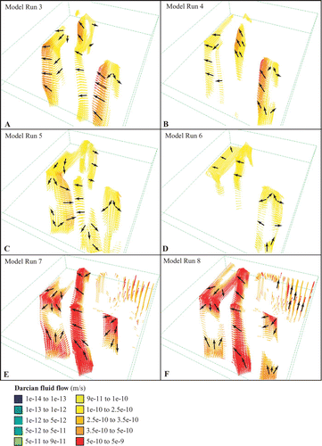
Figure 8 3D representation of cumulative shear strain distribution after 9% shortening in a listric fault scenario: (a) two lithologies, plane strain, with increased initial pore fluid pressure (0.8×lithostatic, Model Run 3); (b) two lithologies, transpression, with increased initial pore fluid pressure (0.8×lithostatic, Model Run 4); (c) three lithologies, plane strain (Model Run 5); (d) three lithologies, transpression (Model Run 6); (e) three lithologies, plane strain, with cell permeability increasing at yield (Model Run 7); (f) three lithologies, transpression, with cell permeability increasing at yield (Model Run 8). Model run numbers relate to .
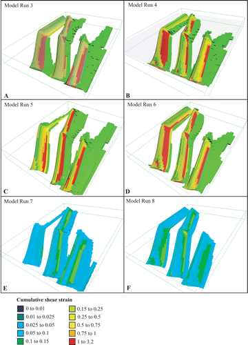
shows the effect of increasing permeability at failure. The faults in these models display significantly lower shear strain than in the previous scenarios; this is compensated by slightly increased shear strain in the wall-rocks (not seen in the figures), as the same bulk strain must be accommodated overall. The reason for this change in behaviour can be explained as follows. Mesh elements in the faults fail earlier than mesh elements in the wall-rocks, because they are weaker (lower cohesion and friction angle: ). Shear failure leads to dilation, which in turn leads to a reduction in pore-fluid pressure. This tends to move the rock away from the yield envelope ( ). Whether the rock continues to fail at the next numerical time-step depends on the rates of fluid-pressure recovery (Mohr's circle moves to the left) and differential stress increase (Mohr's circle expands). Fluid-pressure recovery involves a combination of fluid moving into the failed element from the surrounding elements, and an increase in fluid pressure due to elastic compaction. The rate of fluid-pressure recovery depends on the permeability and fluid pressure of the failed mesh element and the elements surrounding it, and on the rate of bulk shortening. High permeability tends to inhibit fluid-pressure recovery due to compaction because it allows fluid to escape more rapidly as the pore space is reduced. Hence, increasing permeability with shear failure can result in a slower rate of fluid-pressure recovery. In detail, this process involves a complex interplay between the permeability, fluid pressure and mechanical properties of the failed element and the elements that surround it, and the rate of bulk shortening. A pattern of episodic slip may develop if the rates of fluid-pressure recovery and differential stress increase are too slow to bring the Mohr's circle back to the yield envelope within a numerical time-step. Our results indicate that the net effect of increasing permeability at failure is to reduce the amount of shear strain that is accommodated on the faults, indicating that these mesh elements spent less time in a state of shear failure than in previous models, hence stress buildup in the wall-rocks and more shear strain was accommodated there than in models without a permeability increase at failure.
Figure 9 Mohr – Coulomb diagram illustrating the effect of dilation leading to fluid pressure decrease after cell failure.
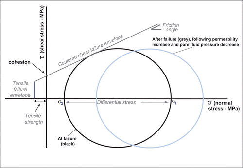
In reality, the sudden increase in permeability at failure would be followed by a gradual decrease due to the combined effects of various sealing mechanisms (Cox Citation1995; Renard et al. Citation2000; Cox et al. Citation2001; Sibson Citation2001; Sheldon & Ord Citation2005), and the pattern of failure and fluid flow would be somewhat different from that predicted by our models. Another possible consequence of increasing permeability with failure is that the fault may become connected with an overpressured fluid reservoir at depth, in which case fluid-pressure recovery would probably occur much more rapidly, and an open, permeable fluid pathway could be sustained for some time following the initial failure event.
Darcian fluid flow
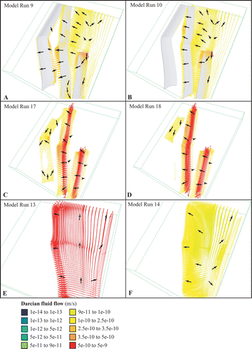
shows the distribution and magnitude of Darcian fluid flow for the set of models shown in . We emphasise the fact that our models have a hydrostatic fluid pressure gradient (at supra-hydrostatic pressures) at the onset of deformation; hence there is no regional flow field. All fluid flow in these models is a consequence of deformation. Localised dilation perturbs the regional hydrostatic pressure gradient, creating local gradients in hydraulic head that drive flow. Dilation provides the driving force for fluid flow in our models, while the magnitude of the fluid flux is controlled primarily by permeability. In our models, fluid flow is concentrated in the fault zones due to their high permeability ( ) and greater amount of dilation than the host-rocks. The northern segment of the listric fault does not generally act as a significant fluid conduit because it is less dilatant than the southern segment. Where fluid flow does occur along the northern segment, it is mainly directed along the fault towards the (more dilatant) southern segment. seems to be an exception to this rule, with significant fluid flow in the northern segment and hardly any in the southern segment. With increased pore-fluid pressure, we note that the magnitude of Darcian fluid flow along the faults increases, especially in the upper half of the faults (). shows a pattern of divergent flow that includes upward, lateral and downward flow in some parts of the faults. In addition, in fluids migrate into the hangingwall along the base of the southern segment of the listric fault. In , fluid flow displays a similar pattern of upward, lateral and downward flow along the faults to that shown in , although in this case fluid flow is of significantly greater magnitude due to increased permeability at failure. In this scenario, the highest upward fluid-flow rates occur in the central fault. Also, disseminated fluid flow can be observed in the northeastern section of the model that represents non-faulted sedimentary rocks (), indicating that this region underwent shear failure and permeability increase despite being outside the fault zones (see discussion above).
Figure 10 3D representation of instantaneous fluid-flow vectors after 9% shortening indicating magnitude of Darcian fluid flow (m/s) for model scenarios as described in . The majority of fluid flow vectors overlap with faults. Black arrows indicate the representative direction of fluid flow (see text for discussion).
Interpretation
Based on the results presented in the previous section, and subject to the limitations of our models, we suggest the following:
(1) An increase in pore-fluid pressure does not significantly affect the distribution and magnitude of shear strain (except for the moderate values of shear strain distributed along the northern segment of the listric fault) and fluid flow in our models. The effect of increased fluid pressure is to reduce the initial values of normal effective stress throughout the model; hence all regions will reach the yield envelope sooner during bulk shortening. However, the same amount of bulk shortening must be accommodated overall, and our results indicate that this is achieved via similar distribution of shear strain as in previous scenarios with lower fluid pressure. Significantly different behaviour would arise if the initial fluid pressure was sufficiently high to cause widespread tensile rather than shear failure; this scenario has not been investigated. We conclude that high permeabilities and structural weakness of the fault zones are the main factors that control the distribution and magnitude of shear strain and fluid flow in our models, rather than the absolute value of pore-fluid pressure.
(2) Changes in lithological parameters do not significantly influence the magnitude of fluid flow and deformation along the faults, but do affect the direction of fluid flow along the listric fault (compare ).
(3) Increase in permeability with cell failure can lead to enhanced fluid flow in the wall-rocks as well as in the faults themselves, as illustrated in , where fluid flow occurs in the northeastern, non-faulted section of the model.
(4) A strong correlation exists between areas of maximum shear strain (i.e. the faults) and areas of maximum Darcian fluid flow in our models. This is partly due to enhanced dilation in the fault zones, and partly due to their high intrinsic permeability. Running some of the models with the same intrinsic permeability throughout the model would reveal the extent to which dilation alone controls fluid flow, but this has not been investigated as part of this study.
Local fluid injection at the base of the model
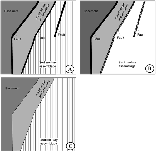
In this section, we present results from model runs 9, 10, 13, 14, 17 and 18 ( ) in which we specify a fixed fluid flux into specific parts of the base of the model as follows: (i) fluid flux (10−10 m/s) into the sedimentary assemblage to simulate a proximal fluid source (i.e. fluid flow dispersed through the sediments: ); (ii) fluid flux (2×10⁻⁹ m/s) into the central and eastern faults to simulate a distal fluid source (i.e. fluid already focused along fault pathways from deeper levels: ); and (iii) a model geometry without faults, and with a fluid flux (2×10⁻⁹ m/s) into the sedimentary assemblage to investigate if preferential fluid-flow pathways would be generated in the absence of existing structural features (). Applying a fluid flux to the base of the model results in an elevated fluid pressure front migrating upwards through the model, as illustrated by curve 2 in . Fluid fluxes are based on Thompson (Citation1997) and amplified by one order of magnitude to obtain illustrative results. These models are intended to represent connectivity with an elevated fluid-pressure source/higher hydraulic head at depth. In these models, permeable faults and localised dilation result in perturbation and focusing of the regional fluid-flow field.
Figure 11 View of base of various model architectures with local fluid injection indicated by dashed lines (see text for discussion): (a) fluid flux into the sedimentary assemblage; (b) fluid flux into the central and eastern faults; (c) fluid flux into the sedimentary assemblage in a no-fault model architecture.
Shear-strain distribution
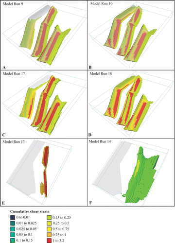
Fluid injection into the sedimentary assemblage or into the central and eastern faults [ : see (i) and (ii) above] does not have a significant impact on the distribution of shear strain when compared with or . Shear strain remains localised along the faults, although there is slightly higher shear strain in the hangingwall of the central and eastern faults near the base of the model than in models without fluid injection, due to elevated fluid pressure in that region (). The models without pre-defined faults () behave quite differently; in , the lithological contrast between the mixed basalt – limestone unit and the sedimentary unit has focused deformation into a narrow region of moderate shear strain, while shows more distributed shear strain in the eastern portion of the model that represents the relatively weak sedimentary unit.
Figure 12 3D representation of cumulative shear strain distribution after 9% shortening in a listric fault scenario with fluid injection over specified regions at the base of the model: (a) plane strain, fluid injected into sedimentary assemblage (Model Run 9); (b) transpression, fluid injected into sedimentary assemblage (Model Run 10); (c) plane strain, fluid injected into central and eastern faults (Model Run 17); (d) transpression, fluid injected into central and eastern faults (Model Run 18); (e) plane strain, fluid injected into sedimentary assemblage and faults absent (Model Run 13); (f) transpression, fluid injected into sedimentary assemblage and faults absent (Model Run 14). Model run numbers relate to .
Darcian fluid flow
Fluid injection into the sediments ( ) results in distributed fluid flow throughout the sedimentary unit, except in the vicinity of faults () where flow becomes focused towards the faults (compare uniform flow in ). This fluid focusing is a consequence of high permeability and a greater degree of dilation in the faults than in the wall-rocks. An interesting consequence of such fluid focusing is that fluid pressure is higher in the sediments far away from the fault than it is close to the fault. The implications of fluid pressure perturbations due to fluid focusing have been discussed by Cox et al. (Citation2001). indicates how fluid flow is amplified and remains restricted along the faults only, when fluids are injected into the faults rather than the surrounding units. Note that minor fluid flow occurs along sections of the listric fault, although no fluids were injected into this fault; this is dilatancy-driven flow, as seen in earlier models ().
Figure 13 3D representation of instantaneous fluid-flow vectors after 9% shortening indicating the magnitude of Darcian fluid flow (m/s) for model scenarios as described in . Fluid-flow vectors overlap with faults in c and d. Black arrows are added to indicate the representative direction of fluid flow (see text for discussion).
Interpretation
The similarity of modelling results presented in this section with previous scenarios suggests that localised fluid injection does not have a major impact on the results, other than to increase the magnitude of the fluid flux in the areas where it is injected. The distribution of shear strain in can be interpreted to represent the development of a shear zone as a result of the lithological contrast between the sedimentary assemblage in the east and the mixed basalt – limestone assemblage in the centre.
Permeable faults disturb the fluid-flow and fluid-pressure fields in the surrounding rocks. Minor faults in the northeast corner of the model (i.e. in the sedimentary unit) would create local foci for fluid flow, potentially explaining how such small structures can become sites of mineralisation when they are located in a regional flow field. It would be interesting to investigate the effect of placing minor faults in different locations relative to the major, fluid-focusing faults, in order to determine the optimum location of such structures for mineralisation.
Based on our observations in , we note that deformation-driven flow along the listric fault is approximately one order of magnitude smaller than the forced flux that was applied to the other two faults. This supports our hypothesis that deformation provides a significant driving force for fluid flow when compared with regional fluid-flow drivers, especially considering that the forced flux applied to the base of the model was increased by a factor of 10 relative to values suggested by Thompson (Citation1997). However, permeability plays a key role in controlling the magnitude of fluid flux that can be attained in a given deformation regime. This is illustrated by , which does not show any obvious enhancement in fluid flux at the lithological boundary despite localisation of shear strain at this site. A different result would have been obtained if permeability had been increased at failure in this model.
Fault bends and terminations
A common characteristic in our models is the presence of enhanced shear strain and fluid flow around fault bends and terminations. , and show that fault bends are invariably associated with high values of shear strain in our models. It seems that these regions at least partly correspond with regions of high fluid flow (although this is not always upward fluid flow) in our models (), or connect to zones of high fluid flow (). In addition, an increase in shear strain and fluid flow can generally be observed around the termination of the eastern fault. In and , localised zones of relatively high shear strain extend along strike from the terminated fault into the host rocks. At the same time, high rates of fluid flow (into or out of the fault) are associated with the termination of the eastern fault (, ), indicating movement of fluids into or out of the host-rocks around the fault termination depending on the model conditions.
Implications for mineralisation in the Hodgkinson Province
The numerical experiments carried out in this study are relatively simplistic and were primarily intended to assess possible controls on deformation and fluid flow in the western part of the Hodgkinson Province (particularly along the northwest-striking segment of the Palmerville Fault). For this purpose, the effects of strike variations and the listric nature of a fault, as well as fault bends and terminations, on the distribution of shear strain and fluid flow (and, by inference, potential for gold mineralisation) are considered.
Regional-scale strike changes
Field observations in the Hodgkinson Province indicate that the Palmerville Fault is a zone of high strain and displacement. The absence of significant hydrothermal alteration and mineralisation along the northern, north-striking segment of the Palmerville Fault suggests that this part of the fault was not associated with significant fluid flow (Vos et al. in press) or dilation. This is consistent with our model results, which generally show lower shear strain and dilation associated with the northern segment of the listric fault (which strikes orthogonal to the far-field compressive stress regime), especially when transpression is applied. Fluid-flow magnitude generally follows the same pattern, being greatest in the southern segment of the listric fault, although this is not always the case ( shows a higher flux in the northern segment). The contrast in behaviour between northern and southern segments of the Palmerville Fault suggests that the difference in strike between the two segments was an important factor that controlled variations in shear strain, fluid flow (and dilation), with deformation and flow being enhanced when the strike is oblique to the shortening direction. Variations in dip are also important (see below). Since our modelling results indicate that under a range of conditions, high shear strain, fluid flow and dilation would be focused along the southern, northwest-trending segment of the listric fault, we infer that this segment was a long-lived zone of weakness that may have formed a preferential pathway for magmas during post-orogenic igneous activity in the Late Carboniferous and Permian. The spatial distribution of intrusions in the Hodgkinson Province that are host to Cu – Au porphyry and skarn mineralisation (Nethery & Barr Citation1998) () supports this notion.
Importance of listric geometry of a terrane-bounding fault
Our comparison of models with different geometries for the westernmost fault suggests that the geometry (listric or planar) of the Palmerville Fault influences slip on other faults to the east. Models with a listric geometry showed significant slip on all faults in the modelled region, whereas the planar geometry resulted in strain being partitioned predominantly into the eastern fault. Fault dip is probably the key control, with the listric fault having a shallower average dip and hence being more favourably oriented for slip than the planar fault.
Although the Palmerville Fault is clearly of regional importance, we note that this terrane-bounding fault remained unmineralised along most of its strike with respect to orogenic-gold mineralisation, while several gold deposits formed along subparallel shear and fault zones ( ) during Middle to Late Palaeozoic episodes of contraction.
Our results suggest that a listric fault geometry promotes slip on faults to the east of the Palmerville Fault, and hence would influence the distribution of mineralisation. What is not clear is why the Palmerville Fault itself remained barren, while minor structures to the east became mineralised. Bierlein et al. (Citation1998) have shown that listric faults may act as significant fluid conduits for the ascent of fluids into upper crustal levels, as is the case in our models. However, many first-order faults do not show evidence for extensive fluid flow that would include, for instance, regional alteration haloes, at least at upper crustal levels. This is consistent with the observation that mineral deposits generally do not form within these first-order faults, and instead are preferentially associated with second-order structures (Cox et al. Citation2001). We postulate that the Palmerville Fault may have formed a deeper crustal décollement zone that accommodated migration of fluids from deeper crustal levels and was tapped by secondary faults that now host gold deposits in the Hodgkinson Province.
Fault bends and terminations
Orogenic-gold deposits form the most widespread ore deposit type that is not related to Carboniferous – Permian magmatism in the Hodgkinson Province (Garrad & Bultitude Citation1999). Peters et al. (Citation1990) suggested that fault splays, intersections and bends exert a strong control on the location of oreshoots in orogenic-gold deposits in the Hodgkinson Province. On a regional scale, our model results similarly indicate that fault bends and terminations can provide a focus for fluid flow. Fault bends in our models are generally associated with regions of higher fluid flow within the fault units. In the case of fault termination, scavenging of fluids from host-rocks at the fault tip can be observed in models with very high fault permeability ( ) and regional fluid injection into the sedimentary rocks (). This is consistent with previous modelling studies, which have shown that fluid is focused into regions of high permeability and/or dilation (Matthai & Roberts Citation1997). Fluid flow from the fault into the host-rocks occurs at the fault tip in models where fluid injection is restricted to the faults only () as a consequence of elevated fluid pressure in the fault relative to the wall-rocks due to fluid injection into the faults.
The findings of our numerical modelling agree well with Cox et al. (Citation2001) who demonstrated that high fluid flow in faults or shear zones is localised into sites with high fracture aperture and/or fracture density, such as jogs, bends and splays. In our models, fault bends and terminations represent important regions for focused fluid flow, and therefore may be interpreted to provide favourable loci for ore deposition.
Application to mineral exploration
Numerical quantification of the relationship between first-order (barren) fault systems and second-order faults that are associated with gold mineralisation, as observed in the Hodgkinson Province, has not previously been illustrated in mineral-exploration scenarios. Our modelling has shown that the geometry of a first-order structure can influence the behaviour of other structures in the region, thus emphasising the importance of studies aimed at constraining the detailed geometry of such structures. This notion, together with insights into more local controls on mineralisation obtained through this modelling exercise (e.g. the significance of fault bends and terminations, and the ability of permeable faults to focus a regional fluid-flow field), can aid future exploration in the Hodgkinson Province, and may also be applicable to analogous terrains elsewhere.
Limitations of modelling
The applicability of our results to real, geological settings hinges on the assumptions on which the models are based, especially those concerning mechanical behaviour, permeability and boundary conditions. The inability to simulate episodic slip (other than through the effect of fluctuating fluid pressure) is a key limitation of modelling in FLAC3D and similar continuum codes. Episodicity of fluid flow may be crucial to the formation of ore deposits, as indicated by incremental vein textures and temporal variability of fluid compositions inferred from fluid inclusions in many (but by no means all) hydrothermal systems (Parry Citation1998; Cox et al. Citation2001; Sibson Citation2001). It might be argued that episodicity is scale-dependent, in both time and space, and that the behaviour of one mesh element in FLAC3D represents the time-averaged behaviour of a geological domain in which multiple slip events take place within one model time-step on a scale much smaller than the mesh element itself. Our models are not intended to simulate behaviour on the scale of individual veins, but rather to simulate the distribution of shear strain and dilatancy on the 100 m to 1 km scale.
It is also worth noting the depth range of the models in this study (top, 12.5 km; base, 18.5 km), which could be close to or even below the brittle – ductile transition, depending on the thermal regime. It is questionable whether episodic slip behaviour is likely to be the dominant mode of fault behaviour at such depths. It is also questionable whether the Mohr – Coulomb constitutive model is appropriate in this region of the crust; a visco-plastic model might be a better choice, but this has not been investigated here.
Issues with fluid pressure boundary conditions were mentioned above. There are several possibilities that could be justified on geological grounds but were not investigated in this study: e.g. fixed fluid flux at the base of the model, with fixed fluid pressure on the top boundary allowing fluid to escape from the top of the model. Different results would be expected with different boundary conditions, but our findings from varying the initial fluid pressure (0.5 to 0.8×lithostatic) suggest that the effects would not be of great significance.
Permeability is probably one of the least well-constrained aspects of any model involving deformation and fluid flow. It is difficult to constrain even the initial permeabilities for our model (see Clauser Citation1992, who highlights the huge range in permeabilities of various rock types, and the scale dependence of permeability), let alone how permeability should vary during deformation. Our approach of assigning high permeabilities to faults, and in some cases allowing permeability to increase at failure, is clearly oversimplified, and more detail could be implemented (e.g. dependence of permeability on volumetric strain and/or fluid pressure) in a more comprehensive study.
Conclusions
Coupled mechanical and fluid-flow numerical modelling carried out on model geometries that resemble the simplified geology of the western Hodgkinson Province have identified several key factors that may have controlled the distribution of shear strain and fluid flow in that province. These factors include changes in regional-scale strike, the listric nature of the terrane-bounding Palmerville Fault, and fault bends and terminations. Variation in strike between the northern and southern segment of the Palmerville Fault, and in particular the orientation of the southern segment of this fault with respect to the regional stress regime, are inferred to be key factors in ground preparation for both fluid flow in the Devonian – Carboniferous, and magmatism in the Late Carboniferous and Permian. The listric fault geometry can be shown to control the distribution and partitioning of shear strain and fluid flow in zones of relatively high permeability and/or low rock strength throughout the model geometry. In the case of a planar fault geometry, all shear strain and fluid flow were shown to be focused on a single structure. This is likely to be the structure with the lowest dip. Our results suggest that the listric nature of the Palmerville Fault may have been crucial for the occurrence of mineralisation associated with second-order faults throughout the western part of the province. Our modelling cannot explain why the first-order Palmerville Fault itself remained barren, but we postulate that the Palmerville Fault may have formed a deeper crustal décollement zone that accommodated migration of fluids from deeper crustal levels, which was tapped by secondary faults that now host gold deposits. Future modelling could investigate fluid-flow patterns that develop in such a regional architecture.
Fault bends and terminations are characterised by high values of shear strain and fluid flow. As such, these locations can be considered prospective for gold mineralisation in the Hodgkinson Province, as was suggested previously by Peters et al. (Citation1990) on the deposit scale. Recognition of these factors and understanding their importance to mineralisation will aid in future exploration in the Hodgkinson Province and similar settings elsewhere, and highlights the applicability of numerical modelling to resolving geoscientific problems.
Acknowledgements
This study forms part of a PhD project carried out by IMAV at the Australian Crustal Research Centre at Monash University. Research has been funded by the Cooperative Research Centre for predictive mineral discovery (pmd∗CRC) and this paper is published with the permission of the CEO, pmd∗CRC. An International Postgraduate Research Scholarship from Monash University is gratefully acknowledged. The numerical modelling could not have been conducted successfully without the assistance of Peter Schaubs, Klaus Gessner and Thomas Poulet at CSIRO. Roberto Weinberg and Klaus Gessner are thanked for comments on the manuscript. The authors are indebted to J. McLellan and S. Cox for feedback and thorough formal reviews of the manuscript. Fractal Technologies is acknowledged for its support in using the FracSIS software package.
References
- Bierlein , F. P. , Fuller , T. , Stüwe , K , Arne , D. C. and Keays , R. R. 1998 . Wallrock alteration associated with turbidite-hosted gold deposits: examples from the Palaeozoic Lachlan fold belt in central Victoria, Australia . Ore Geology Reviews , 13 : 345 – 380 .
- Bultitude , R. J. , Garrad , P. D. , Donchak , P. J. T. , Domagala , J. , Champion , D. C. , Rees , I. D. , Mackenzie , D. E. , Wellman , P. , Knutson , J. , Fanning , C. M. , Fordham , B. G. , Grimes , K. G. , Oversby , B. S. , Rienks , I. P. , Stephenson , P. J. , Chappell , B. W. , Pain , C. F. , Wilford , J. R. , Rigby , J. F. and Woodbury , M. J. 1997 . “ Cairns region ” . In North Queensland Geology Edited by: Bain , J. H. C. and Draper , J. J. 225 – 325 . Australian Geological Survey Organisation Bulletin 240
- Clauser , C. 1992 . Permeability of crystalline rocks . EOS , 73 : 231 – 237 .
- Cox , S. F. 1995 . Faulting processes at high fluid pressures—an example of fault valve behavior from the Wattle Gully Fault, Victoria, Australia . Journal of Geophysical Research , 100 : 12841 – 12859 .
- Cox , S. F. , Knackstedt , M. A. and Braun , J. 2001 . Principles of structural control on permeability and fluid flow in hydrothermal systems . Reviews in Economic Geology , 14 : 1 – 24 .
- Cundall , P. J. and Board , M. 1988 . “ A microcomputer program for modelling large-strain plasticity problems ” . In Numerical Methods in Geomechanics: Proceedings of the 6th International Conference on Numerical Methods in Geodynamics , Edited by: Swoboda , C. 2101 – 2108 . Balkema : Rotterdam .
- Fractal Technologies . 2004 . FracSIS Professional 5.0 User Manual , West Perth : Fractal Technologies .
- Garrad , P. D. and Bultitude , R. J. 1999 . Geology, mining history and mineralisation of the Hodgkinson and Kennedy Provinces, Cairns region, North Queensland . Queensland Minerals and Energy Review Series ,
- Groves , D. I. , Goldfarb , R. J. , Gebre-Mariam , M. , Hagemann , S. G. and Robert , F. 1998 . Orogenic gold deposits: a proposed classification in the context of their crustal distribution and relationship to other gold deposit types . Ore Geology Reviews , 13 : 7 – 27 .
- Itasca . 2002 . FLAC3D: Fast Lagrangian Analysis of Continua in 3 dimensions , Minneapolis : Itasca Consulting Group Inc. .
- Matthai , S. K. and Roberts , S. G. 1997 . “ Transient versus continuous fluid flow in seismically active faults: an investigation by electric analogue and numerical modelling ” . In Fluid Flow and Transport in Rocks , Edited by: Jamtveit , B. and Yardley , B. W. D. 263 – 296 . London : Chapman & Hall .
- Nethery , J. E. and Barr , M. J. 1998 . “ Red Dome and Mungana gold – silver – copper – lead – zinc deposits ” . In Geology of Australian and Papua New Guinean Mineral Feposits Edited by: Berkman , D. A. and Mackenzie , D. H. 723 – 728 . Australasian Institute of Mining and Metallurgy Monograph 22
- Oliver , N. H. S. , Ord , A. , Valenta , R. K. and Upton , P. 2001 . Deformation, fluid flow, and ore genesis in heterogeneous rocks, with examples and numerical models from the Mount Isa district, Australia . Reviews in Economic Geology , 14 : 51 – 73 .
- Ord , A. 1991 . Deformation of rock: a pressure-sensitive, dilatant material . Pure and Applied Geophysics , 137 : 337 – 366 .
- Ord , A. , Hobbs , B. E. and Regenauer-Lieb , K. 2004 . A smeared seismicity constitutive model . Earth Planets and Space , 56 : 1121 – 1133 .
- Ord , A. and Oliver , N. H. S. 1997 . Mechanical controls on fluid flow during regional metamorphism: some numerical models . Journal of Metamorphic Geology , 15 : 345 – 359 .
- Parry , W. T. 1998 . Fault-fluid compositions from fluid-inclusion observations and solubilities of fracture-sealing minerals . Tectonophysics , 290 : 1 – 26 .
- Peters , S. G. , Golding , S. D. and Dowling , K. 1990 . Melange- and sediment-hosted gold-bearing quartz veins, Hodgkinson Gold Field, Queensland, Australia . Economic Geology , 85 : 312 – 327 .
- Renard , F. , Gratier , J. P. and Jamtveit , B. 2000 . Kinetics of crack-sealing, intergranular pressure solution, and compaction around active faults . Journal of Structural Geology , 22 : 1395 – 1407 .
- Sheldon , H. A. and Ord , A. 2005 . Evolution of porosity, permeability and fluid pressure in dilatant faults post-failure: implications for fluid flow and mineralization . Geofluids , 5 : 272 – 288 .
- Sibson , R. H. 2001 . Seismogenic framework for hydrothermal transport and ore deposition . Reviews in Economic Geology , 14 : 25 – 50 .
- Sillitoe , R. H. 2000 . Gold-rich porphyry deposits: descriptive and genetic models and their role in exploration and discovery . Reviews in Economic Geology , 13 : 315 – 345 .
- Sorjonen-Ward , P. , Zhang , Y. and Zhao , C. 2002 . Numerical modelling of orogenic processes and gold mineralisation in the southeastern part of the Yilgarn Craton, Western Australia . Australian Journal of Earth Sciences , 49 : 935 – 964 .
- Thompson , A. B. 1997 . “ Flow and focusing of metamorphic fluids ” . In Fluid Flow and Transport in Rocks , Edited by: Jamtveit , B. and Yardley , B. W. D. 297 – 314 . London : Chapman & Hall .
- Turcotte , D. L. and Schubert , G. 1982 . Geodynamics: Applications of Continuum Physics to Geological Problems , New York : John Wiley and Sons .
- Vermeer , P. A. and de Borst , R. 1984 . Non-associated plasticity for soils, concrete and rock . Heron , 29 : 1 – 62 .
- Vos , I. M. A. and Bierlein , F. P. 2006 . Characteristics of orogenic gold deposits in the Northcote district, Hodgkinson Province, north Queensland: implications for tectonic evolution . Australian Journal of Earth Sciences , 53 : 469 – 484 .
- Vos , I. M. A. , Bierlein , F. P. , Barlow , M. A. and Betts , P. G. The Palmerville Fault, NE Queensland, Australia: a multi-disciplinary approach to understanding major fault systems . Journal of Structural Geology , (in press)
- Vos , I. M. A. , Bierlein , F. P. , Murphy , F. C. and Barlow , M. 2004 . The mineral potential of major fault systems: case studies from northeastern Queensland, Australia . Geoscience Australia Record , 2004/09 : 209 – 212 .
- Vos , I. M. A. , Bierlein , F. P. and Webb , J. 2006 . Geochemistry of Early Palaeozoic basalts in the Hodgkinson Province: a key to tectono-magmatic evolution of the Tasman Fold Belt System in northeastern Queensland, Australia . International Journal of Earth Sciences , 95 : 569 – 585 .