Abstract
Control of the synchronous generator, also referred to as an alternator, has always remained very significant in power system operation and control. Alternator output is proportional to load angle, but as the parameter is moved up, the power system security approaches the extreme limit. Hence, generators are operated well below their steady state stability limit for the secure operation of a power system. This raises demand for efficient and fast controllers. Artificial intelligence, specifically artificial neural network (ANN), is emerging very rapidly and has become an efficient tool for operation and control of power systems. ANN requires considerable time to tune weights, but it is fast and accurate once tuned properly. Previously, ANNs have been trained with high-dimensional input space or have been trained online. Hence, either one requires considerable time to yield the control signal or is a bit risky technique to apply in interconnected power systems. In this study, a multilayer perceptron (MLP) ANN is proposed to control generator excitation trained with low-dimensional input space. Moreover, MLP has been trained offline to avert the risk potential of online training. The results illustrate preeminence of the proposed neurocontroller-based excitation system over the conventional controllers-based excitation system.
INTRODUCTION
A power grid is a complex and variable network with many operational levels made up of a wide range of energy sources with numerous interaction points (Venayagamoorthy and Harley Citation2001). Following ever-growing industrialization and population, the demand for electric power supply is continuously increasing. Because of the de-regularization of power systems, the current trend is toward interconnected networks of transmission lines linking generators with loads in different areas, leaving power system security at high risk (Vittal Citation2000; Shahidehpour, Tinney, and Fu Citation2005).
Transient stability and small-signal stability analysis are essential components of power system security (Vittal Citation2000). Recently, power systems have gained more attention from researchers in employment of nonlinear controllers, particularly for transient stability enhancement. The results have shown much improvement over considerable operating range (Johansson, Angquist, and Nee Citation2010). However, nonlinear controllers are complicated, difficult to implement, and require the exact system modeling. The computational intelligence methods, in particular the artificial neural networks, have shown to be able to provide opportunity to overcome the aforementioned problems of nonlinear control (Venayagamoorthy and Harley Citation2001).
Artificial neural networks (ANNs) are parallel distributed processing systems capable of synthesizing a complex, transparent, and highly nonlinear mapping from space of input features to output space (Fukuda and Shibata Citation1992; Basheer and Hajmeer Citation2000; Rafienia et al. Citation2010). ANN, with its learning ability, avoids the complex mathematical analysis in solving control problems when plant dynamics are complex and highly nonlinear. This is a distinct advantage over the traditional nonlinear control methods (Fukuda and Shibata Citation1992). Learning a general solution is not only an important capability but also offers high processing speed at the same time (Bishop Citation1994).
The use of ANN in power system control is not new (Vankayala and Rao Citation1993). Both the static and dynamic neural networks have found many applications, ranging from generator control (Amjady and Majedi Citation2007; Cabrera-Vázquez et al. Citation2007; Felix, Sanchez, and Loukianov Citation2009), high-voltage DC transmission (HVDC; Dash, Routray, and Mishra Citation1999; Mazon et al. Citation2001; Yilmaz et al. Citation2007), flexible AC transmission (FACTS; Gwang Won and Lee Citation2005; Ma Citation2007; Modi, Singh, and Sharma Citation2007), motor control (Kowalski and Orlowska-Kowalska Citation2003; Ren and Chen Citation2006; Nouri, Dhaouadi, and Braiek Citation2008), to power quality enhancement (Jayasree, Devaraj, and Sukanesh Citation2009). In fact, a work (Sharaf and Lie Citation1994) has proposed an ANN-based classification of stability detection, based on the loss of excitation or short circuit, and it also has considered the severity of fault. Patterns from simulated data have been extracted using fast Fourier transform (FFT) and used as input to ANN for the classification. The reported results are not satisfactory because of the used stopping criterion.
Djukanovic and colleagues (Citation1995) designed an ANN-based controller for a third-order generator model with a static (ST-1) excitation system. In the article, the feedback-coordinated stabilizing control law is treated as a mapping from the space of actual system measurement to the space of synthesized control actions. The chosen ANN considered 49 input features, had no hidden nodes, and had two output nodes trained up to least-square-error reduced to 0.000007.
A radial basis function (RBF)-based controller with six input vectors has been conceived to replace AVR (Swidenbank et al. Citation1999). In Venayagamoorthy and Harley (Citation2001) two 3-layer multilayer perceptron (MLP) with time-delayed inputs neural networks, trained online for a static excitation (ST-1) system and turbine control of a turbo generator, have been reported. The intelligent controller consists of a neuro-identifier (NI) and a neurocontroller (NC). The NI and NC, having twelve and six inputs respectively, have been trained through unsupervised learning. The NC used 80 weights. The work by Venayagamoorthy and Harley (Citation2002) is an extension of Venayagamoorthy and Harley (Citation2001). Instead of using one NC for both excitation and turbine, separate NCs have been employed to reduce the computational burden on the controller. The results show slight improvement because of the lesser computational burden (Venayagamoorthy and Harley Citation2002). In this architecture, each NC has used 56 weights.
MLP and RBF are types of a static feed-forward neural network and both are universal approximators. For the approximation of nonlinear input/output mapping, MLP normally requires a fewer number of parameters than RBF, for the same degree of accuracy. It is well known that during adaptation, the variance of Gaussians can become very broad, and hence, RBF may lose its local nature. Complex implementation and huge memory requirement are demerits of dynamic neural networks. Unsupervised technique is very risky and is prone to instability. Supervised learning is efficient because of the availability of more information sources than are available for unsupervised learning. Moreover, as ANN tends toward local optima traps, it is very risky to train ANN online for controlling power systems using error-backpropagation methods (Abro and Mohamad-Saleh Citation2012).
The simple architecture and low memory requirement has made MLP an attractive choice for mapping any complex function. MLP constitutes of input, hidden, and output layers. A hidden layer adds the nonlinear learning capability to MLP. In most function-approximation problems, one hidden layer is sufficient to approximate any continuous function (Bishop Citation1994; Basheer and Hajmeer Citation2000). ANN architecture selection is a multifaceted problem. An ANN with minimum size is less likely to learn the idiosyncrasies or noise in the training data, and hence, may generalize the data more appropriately (Bishop Citation1994; Swidenbank et al. Citation1999).
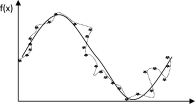
A highly challenging characteristic for a trained ANN is how well it performs when presented with a new set of data; in other words, the data that it has not seen before. This is referred to as the generalization characteristic and it is an essential feature of an ANN. Figure illustrates this characteristic. Typically, the data is scattered as a result of noise. This requires an ANN with the appropriate degree of flexibility to learn the trend in the data (solid line) without tightly overfitting the data (dotted line).
FIGURE 1 Showing generalization (solid line) versus overfitting phenomenon (dotted line).
Another important criterion of ANN training is its stopping condition. Most of the previous research works relied on the mean error as the stopping condition for the ANN training, which resulted in the poor generalization. This training-stopping condition is ambiguous because training error decreases with every subsequent run, irrespective of ANN learning. Moreover, high-dimensional and intercorrelated input data, for ANN training, increases processing elements and, consequently, the information-processing time. Therefore, decreasing dimensions of input space may enhance the performance of an ANN-based controller.
This article is divided into three phases. The immediate phase describes the impact of high-speed AVR on power system transient stability. The second phase focuses on the model simulation, and the last phase discusses results.
EFFECT OF FAST-ACTING AVR ON POWER SYSTEM STABILITY
A power system comprises generation, transmission, and distribution systems. The synchronous generator, a prime element of a power system, comprises the stator (also called the armature), and the rotor (also known as the field). The field is responsible for spreading magnetic flux in an air gap. For proper operation of a synchronous generator, the prime condition is synchronism between armature and field. Strength of the synchronism largely depends on the strength of air-gap magnetic flux. Furthermore, the excitation system is responsible for keeping air-gap flux strength constant. The synchronism can be jolted by faults induced anywhere in a power system, but the extreme disturbance is fault introduced at the terminals of a generator. Fault deteriorates the strength of magnetic flux, as explained by an armature reaction phenomenon, and so affects the synchronism. The mechanical angle between rotor magnetic field and armature magnetic flux of a generator is known as the load angle or power angle, symbolized as δ.
Power system stability is the ability of an electric power system to regain a state of operating equilibrium after being subjected to a physical disturbance or fault. In addition, neither a unit at a generating station nor a portion of a power system should lose synchronism with respect to the generating station or the power system (Kundur et al. Citation2004). Power system stability is divided into three major types; angle stability, voltage stability, and frequency stability. These are further classified into transient and small-signal stability according to the magnitude of disturbance. In transient stability, disturbances are considered to be sufficiently large that linearization of system equations do not hold true, whereas, in small-signal stability, disturbances are conceived to be small, and thus linearization of system equations holds true (Kundur et al. Citation2004). Power system stability may be enhanced by either reducing the first swing or by enhancing system damping (Machowski, Bialek, and Bumby Citation2008). In the power system, a three-phase-to-ground fault is a large disturbance, hence, the fault type has been considered in this simulation work. In Figure , the power transfer capability of a system with respect to active power, voltage, and power factor has been illustrated. The figure also shows the relationship of active power, voltage, and power factor.
FIGURE 2 Relationship between voltage, active power, and power factor.
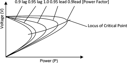
7As the figure shows, an increase in power factor from lagging (lag) to leading (lead) increases voltage level and consequently increases the active power-transfer capability and vice versa. Fault current is highly inductive in nature as is evident from Figure . Voltage drop is higher at more lagging power factor. During fault, drop in voltage drops the electrical power transfer from its pre-fault value to a very low level. However, input mechanical power remains the same because of a slow-responding turbine. This difference in input mechanical power (P m ) and output electrical power (P em ) generates positive accelerating power (P a ), as given in the following equation.
FIGURE 3 Variation of active power in relation to load angle.
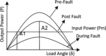
Area A1 is the area associated with acceleration of the generator during fault, and A2 is the deceleration area during the post-fault. Higher A2 assures power system stability. Power system stability can be enhanced by decreasing area A1, which will ultimately lead to increasing A2. A1 may be reduced either by removing the fault early or by increasing the magnitude of electrical power output during fault. There are many methods to dampen oscillations and restore the pre-fault equilibrium point, but the methods employed in this study are damper winding and excitation control (AVR + Exciter).
The induction of electromagnetic torque (T em ) in damper winding against any speed deviation from synchronous speed is based on Lenz's law. The magnitude of T em is higher for even small speed change, and nonlinear behavior can be observed at higher slip values. The stronger the excitation system, the more effective will be the role of damper windings in damping out the oscillations (Machowski, Bialek, and Bumby Citation2008).
The fault causes a decrease in air-gap flux density. However, decrease in air-gap flux density depends on the direct and quadrature (d-q) axis' subtransient and transient time constant and the duration of fault. Moreover, it also depends on the total decrease in terminal voltage. This leads to increase in ΔV, so the output of the excitation system will shoot up to compensate the error. Transient stability may be enhanced by rapidly increasing excitation current (Wang et al. Citation1993). The fast-acting excitation systems can increase the excitation up to its ceiling value before clearance of the fault. This has two positive effects (Machowski, Bialek, and Bumby Citation2008):
| 1. | It causes increase in E′ (transient voltage), so the accelerating power decreases. | ||||
| 2. | When the fault is cleared, the system will follow higher-power angle characteristics owing to new E′. This will increase the decelerating area. | ||||
The effect of fast excitation on oscillations can be well explained by Equation (Equation2).
The E
t
(terminal voltage) reaches its minimum when δ′ equals π/2. However, the minimum value of E
t
is dependent on value. The case considered in this simulation is
. Hence, after removal of fault, E
t
recovers well in spite of large δ′ values. Consequently, this high terminal voltage will force the AVR to reduce the field current, and thus, a decrease in back swing is achieved. This will reduce the subsequent forward and backward swings, hence, effective damping occurs.
This article considers an existing multimachine power plant. The multimachine plant has been converted to single-machine infinite bus system (SMIB), which simulates a single generator connected with the rest of the power system. The excitation model considered here is as per IEEE 2005 recommendation (2006). The high initial response excitation system AC4A has been modeled as shown in Figure . It utilizes a full wave-controlled bridge rectifier, and only AC-type excitation systems allow negative-field voltage forcing.
FIGURE 4 The exciter AC4A model.
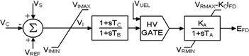
In Figure , VC is the compensating voltage, used to keep voltage constant at any preset point. It is given by
The VUEL is under excitation limiter (UEL) voltage. UEL senses a combination of voltage and current of the synchronous generator. The UEL output is applied in the voltage regulator at the HV gate to override the normal action of the voltage regulator (Figure ). Its function is to prevent overheating of the stator-end region of the synchronous machine.
SIMULATION AND IMPLEMENTATION
The power system model considered in this work is shown in Figure . The parameters of the generator are given in Table , where X′d is the subtransient direct axis reactance, X′q is the subtransient quadrature axis reactance, T is the time constant, (″) indicates transient and K is a constant. The excitation system is proportional-and-integrator (PI) controlled. The PI controller is simple to implement, yet very effective in damping an oscillatory mode (Guo, Crow, and Sarangapani Citation2009). Figure shows PI-compensated AVR and exciter. Their parameters are given in Table .
FIGURE 5 Single machine-infinite bus model.
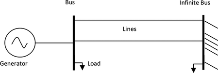
FIGURE 6 Block diagram of AVR and exciter combination.
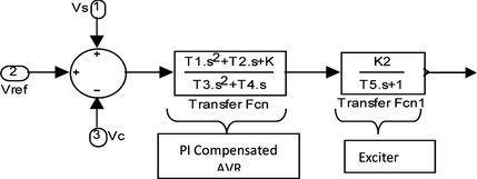
TABLE 1 The Simulated Synchronous Generator Parameters
TABLE 2 Parameters of Excitation System (see Figure 6)
The turbine model has been the same during testing of both conventional controller and NC. The compensating point considered for VC is the terminals of the generator. Initially, the VUEL was not considered in this simulation. Later, it was observed that after the fault clearance, as exciter output falls below zero value, the induction motor, connected at infinite bus, experiences a problem in restoring pre-fault electromagnetic torque. This ultimately leads to load angle oscillations at the generator end, which urges the use of VUEL. Interested readers can find a modeling explanation of VUEL (see 2006).
MLP has been used in this work because of its advantages discussed in the previous section. In this work, generated data have been divided into three parts: training, validation, and testing in 4:2:4 ratios. To avoid the overfitting problem, a method called validation has been employed to stop the training process instead of using training error. The best MLP has been selected based on the one with the smallest test error.
The basic work stages are shown in the flow chart in Figure . MLPs have been trained on the randomized data based on a 60 msec three-phase-to-ground fault at load (0.051 + j0.24) Ω. Simulation of the model has been carried out on MATLAB/Simulink. 13.8 KV, 300 MW, 50 Hz generator simulates the combinedmultimachine system. Training of ANN has been tried with different sampling rates. The minimum error has been obtained at four samples per cycle.
FIGURE 7 ANN training flow chart.
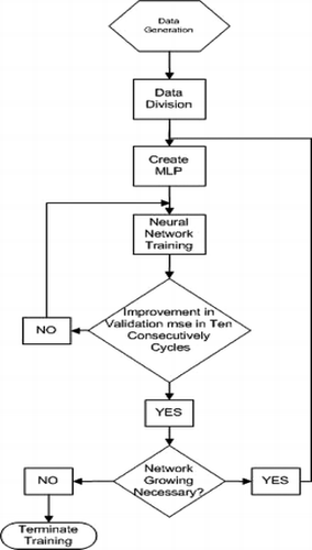
The network growing technique has been used to obtain an optimal MLP size. Network growing basically adds one hidden node at a time into the ANN. Each hidden node employs a sigmoidal activation function. Output of the simulated network has been obtained on the sequential data. Every time MLP size has been grown by adding an extra hidden node, ANN weight tuning has been carried out thirty times with random initial weights. At the end of every tuning, the mean square error (MSE) and mean absolute error (MAE) of the datasets have been calculated. The best MLP has been selected on the basis of minimum MSE and MAE of the test dataset.
For every MLP, the same training method has been carried out for four different well-known learning algorithms: the Levenberg–Marquardt error backpropagation (LM), Bayesian regularization (BR), resilient backpropagation (RP), and gradient descent with momentum (GDM) to investigate the differences in their performance.
RESULTS AND DISCUSSION
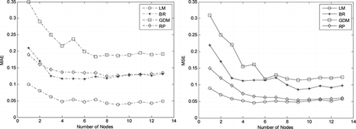
The results of MLP prediction with different learning algorithms and with different numbers of hidden nodes are shown in Figure . The supremacy of LM error backpropagation is very evident from Figure . Initially, very rapid decline of error in all the learning algorithms can be observed, but soon they attend saturation level. The MAE of RP is initially lesser than BR, but afterward, BR supersedes RP. The MLP with GDM converges very slowly, and its convergence is the slowest among all the compared algorithms. MAE and MSE error magnitudes of LM are the least for MLP, which has nine hidden neurons. Hence, the selected MLP for representing the problem is a three-layer MLP with two input nodes, nine sigmoidal hidden nodes, and one linear output node. With sigmoidal hidden nodes, the universal approximation properties of the MLP hold even if the output units have linear activation function.
FIGURE 8 MSE and MAE with change in hidden nodes of different learning algorithms.
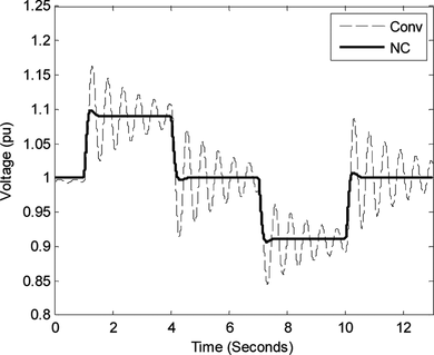
Figures and show two plots of change in terminal voltage with respect to ∓10% change in reference voltage at load (0.051 + j0.024) Ω and load (0.007 + j0.004) Ω. The figures clearly depict the superiority of the NC over the conventional controller (Conv). As mentioned earlier, the conventional controller is a PI controller. At higher load, with the conventional controller at the end of 3 s, the generator was not able to attend a steady state position as it did at lower load. However, with the NC, the system neither oscillates at the lower load nor at the higher load conditions. The NC has been trained by the conventional controller data, but the NC controller has appropriately extracted the trend in the data and, hence, resulted in better performance than the conventional controller.
FIGURE 9 Performance at ±10 change to Vref at (0.051 + j0.24) Ω.
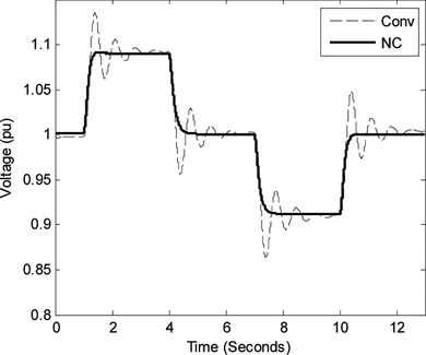
FIGURE 10 Performance at ±10 Change to Vref at (0.007 + j0.004) Ω.
Figures and show the terminal voltage and load angle response after removal of 120 ms three-phase-to-ground fault, at lower load. Before and after the fault, the terminal voltage produced by the conventional controller and the NC is overlapping. Nevertheless, a few oscillations can be observed immediately after the clearance of the fault using the conventional controller. Overshoot and drop in voltage are more evident with the conventional controller than with the NC, whereas oscillations in load angle have been damped out almost equally by the conventional controller and the NC.
FIGURE 11 Terminal voltage; 120 ms fault at (0.051 + j0.24) Ω load.
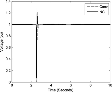
FIGURE 12 Load angle; 120 ms fault at (0.051 + j0.24) Ω.
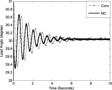
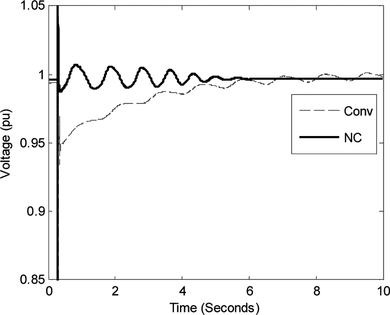
In Figures and , nonlinear capability of the NC has been depicted. At higher load, 120 ms fault has been simulated at generator terminals. Both figures show dominance of NC over conventional controller more vividly. The perfomance of the conventional controller deteriorates more as the system moves away from its linearized point. Again, during and after removal of a fault, the voltage drop and the voltage rise for the conventional controller has been more than that for the NC. To clearly show the voltage fluctuations after removal of the fault, that portion has been clipped. In addition, the rise and settling of steady-state terminal voltage with the NC is far ahead of that of the conventional controller, whereas load angle comparison shows the asymptotically unstable behavior of the conventional controller and the stable behavior of the NC. In addition, the first swing of the NC is also lesser than the conventional controller in both figures.
FIGURE 13 Load angle; 120 ms fault at (0.007 + j0.004) Ω.
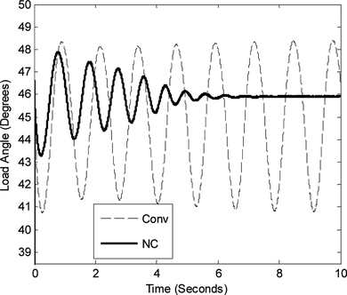
FIGURE 14 Terminal voltage; 120 ms fault at (0.007 + j0.004) Ω.
CONCLUSION
In this article, the effect of fast-acting excitation systems on transient stability and voltage regulation has been demonstrated. The adaptive and nonlinear nature of an MLP-based neurocontroller has also been explained and verified. The proposed neurocontroller has been trained on low-dimensional input space of actual signals and has been trained offline. Data for the proposed neurocontroller training has been generated using the conventional PI-controller. However, the proposed neurocontroller trained on the data has outperformed the conventional controller for generator-excitation control. The proposed neurocontroller is easier to design in comparison with conventional adaptive and gain-scheduling nonlinear controllers. Moreover, offline training of neurocontrollers is simpler than online training. Furthermore, it is more secure to install offline-trained neurocontrollers than online-trained neurocontrollers. Also, the proposed neurocontroller allows generators to be operated closer to their steady-state stability limits and hence, release in their capacity. Therefore, the proposed neurocontroller-based generator can carry a higher load in comparison to the conventional controller-based generator.
Acknowledgments
The authors gratefully acknowledge the Institute of Postgraduate Studies, University Sains Malaysia, fellowship scheme for the financial support.
REFERENCES
- 2006. IEEE recommended practice for excitation system models for power system stability studies. IEEE Std 421.5–2005 (Revision of IEEE Std 421.5–1992): 0–1–85 .
- Abro , A. G. , and J. Mohamad-Saleh . 2012 . Control of power system stability – reviewed solutions based on intelligent systems . International Journal of Innovative Computing, Information and Control 8 ( 10(A) ): 6643 – 6666 .
- Amjady , N. , and S. F. Majedi . 2007 . Transient stability prediction by a hybrid intelligent system . IEEE Transactions on Power Systems 22 ( 3 ): 1275 – 1283 .
- Basheer , I. A. , and M. Hajmeer . 2000 . Artificial neural networks: Fundamentals, computing, design, and application . Journal of Microbiological Methods 43 ( 1 ): 3 – 31 .
- Bishop , C. M. 1994 . Neural networks and their applications . Review of Scientific Instruments 65 ( 6 ): 29 .
- Cabrera–Vázquez , J. , A. G. Loukianov , J. M. Cañedo , and V. L. Utkin . 2007 . Robust controller for synchronous generator with local load via VSC . International Journal of Electrical Power & Energy Systems 29 ( 4 ): 348 – 359 .
- Dash , P. K. , A. Routray , and S. Mishra . 1999 . A neural network based feedback linearising controller for HVDC links . Electric Power Systems Research 50 ( 2 ): 125 – 132 .
- Djukanovic , M. , M. Novicevic , D. Dobrijevic , B. Babic , D. J. Sobajic , and Y.-H. Pao . 1995 . Neural-net based coordinated stabilizing control for the exciter and governor loops of low head hydropower plants . IEEE Transactions on Energy Conversion 10 ( 4 ): 760 – 767 .
- Felix , R. A. , E. N. Sanchez , and A. G. Loukianov . 2009 . Neural block control for synchronous generators . Engineering Applications of Artificial Intelligence 22 ( 8 ): 1159 – 1166 .
- Fukuda , T. , and T. Shibata . 1992 . Theory and applications of neural networks for industrial control systems . IEEE Transactions on Industrial Electronics 39 ( 6 ): 472 – 489 .
- Guo , J. , M. L. Crow , and J. Sarangapani . 2009 . An improved UPFC control for oscillation damping . IEEE Transactions on Power Systems 24 ( 1 ): 288 – 296 .
- Gwang Won , K. , and K. Y. Lee . 2005 . Coordination control of ULTC transformer and STATCOM based on an artificial neural network . IEEE Transactions on Power Systems 20 ( 2 ): 580 – 586 .
- Jayasree , T. , D. Devaraj , and R. Sukanesh . 2009 . Power quality disturbance classification using S–Transform and radial basis network . Applied Artificial Intelligence: An International Journal 23 ( 7 ): 680 – 693 .
- Johansson , N. , L. Angquist , and H.-P. Nee . 2010 . An adaptive controller for power system stability improvement and power flow control by means of a thyristor switched series capacitor (TSSC) . IEEE Transactions on Power Systems 25 ( 1 ): 381 – 391 .
- Kowalski , C. T. , and T. Orlowska-Kowalska . 2003 . Neural networks application for induction motor faults diagnosis . Mathematics and Computers in Simulation 63 ( 3–5 ): 435 – 448 .
- Kundur , P. , J. Paserba , V. Ajjarapu , G. Andersson , A. Bose , C. Canizares , N. Hatziargyriou , D. Hill , A. Stankovic , C. Taylor , T. Van Cutsem , and V. Vittal . 2004. Definition and classification of power system stability IEEE/CIGRE joint task force on stability terms and definitions. IEEE Transactions on Power Systems 19 (3): 1387–1401.
- Ma , T.-T. 2007 . P-Q decoupled control schemes using fuzzy neural networks for the unified power flow controller . International Journal of Electrical Power & Energy Systems 29 ( 10 ): 748 – 758 .
- Machowski , J. , J. Bialek , and J. R. Bumby . 2008 . Power system dynamics stability and control . West Sussex , UK : John Wiley & Sons Ltd .
- Mazon , A. J. , I. Zamora , J. Gracia , K. J. Sagastabeutia , and J. R. Saenz . 2001 . Selecting ANN structures to find transmission faults . Computer Applications in Power, IEEE 14 ( 3 ): 44 – 48 .
- Modi , P. K. , S. P. Singh , and J. D. Sharma . 2007 . Voltage stability evaluation of power system with FACTS devices using fuzzy neural network . Engineering Applications of Artificial Intelligence 20 ( 4 ): 481 – 491 .
- Nouri , K. , R. Dhaouadi , and N. B. Braiek . 2008 . Adaptive control of a nonlinear dc motor drive using recurrent neural networks . Applied Soft Computing 8 ( 1 ): 371 – 382 .
- Rafienia , M. , M. Amiri , M. Janmaleki , and A. Sadeghian . 2010 . Applications of artificial neural networks in controlled drug delivery systems . Applied Artificial Intelligence: An International Journal 24 ( 8 ): 807 – 820 .
- Ren , T.-J. , and T.-C. Chen . 2006 . Robust speed–controlled induction motor drive based on recurrent neural network . Electric Power Systems Research 76 ( 12 ): 1064 – 1074 .
- Shahidehpour , M. , F. Tinney , and Y. Fu . 2005 . Impact of security on power systems operation . In Proceedings of the IEEE 93 ( 11 ): 2013 – 2025 .
- Sharaf , A. M. , and T. T. Lie . 1994 . ANN based pattern classification of synchronous generator stability and loss of excitation . IEEE Transactions on Energy Conversion 9 ( 4 ): 753 – 759 .
- Swidenbank , E. , S. McLoone , D. Flynn , G. W. Irwin , M. D. Brown , and B. W. Hogg . 1999 . Neural network based control for synchronous generators . IEEE Transactions on Energy Conversion 14 ( 4 ): 1673 – 1678 .
- Vankayala , V. S. S. , and N. D. Rao . 1993 . Artificial neural networks and their applications to power systems––A bibliographical survey . Electric Power Systems Research 28 ( 1 ): 67 – 79 .
- Venayagamoorthy , G. K. , and R. G. Harley . 2001 . A continually online trained neurocontroller for excitation and turbine control of a turbogenerator . IEEE Transactions on Energy Conversion 16 ( 3 ): 261 – 269 .
- Venayagamoorthy , G. K. , and R. G. Harley . 2002 . Two separate continually online-trained neurocontrollers for excitation and turbine control of a turbogenerator . IEEE Transactions on Industry Applications 38 ( 3 ): 887 – 893 .
- Vittal , V. 2000 . Consequence and impact of electric utility industry restructuring on transient stability and small-signal stability analysis . In Proceedings of the IEEE 88 ( 2 ): 196 – 207 .
- Wang , Y. , D. J. Hill , L. Gao , and R. H. Middleton . 1993 . Transient stability enhancement and voltage regulation of power systems . IEEE Transactions on Power Systems 8 ( 2 ): 620 – 627 .
- Yilmaz , S. , H. Dincer , I. Eksin , and O. Kalenderli . 2007 . Heat control in HVDC resistive divider by PID and NN controllers . Energy Conversion and Management 48 ( 10 ): 2739 – 2748 .