Abstract
Biogeography is the study of distribution of biological species, over space and time, among random habitats. Recently developed Biogeography-Based Optimization (BBO) is a technique in which solutions of the problem under consideration are named habitats; just as there are chromosomes in genetic algorithms (GAs) and particles in Particle Swarm Optimization (PSO). Feature sharing among various habitats in other words, exploitation, is made to occur because of the migration operator, whereas exploration of new SIV values, similar to that of GAs, is accomplished with the mutation operator. In this study, the nondominated sorting BBO (NSBBO) and various migration variants of the BBO algorithm, reported to date, are investigated for multiobjective optimization of six-element Yagi–Uda antenna designs to optimize two objectives, viz., gain and impedance, simultaneously. The results obtained with these migration variants are compared, and the best and the average results are presented in the concluding sections of the article.
INTRODUCTION
An antenna is an electrical device that acts as an interface between free-space radiations and a transmitter (or receiver). The choice of an antenna depends on many factors such as requisite gain, impedance, bandwidth and frequency of operation, and so on. The antenna is simple to construct and has a high gain typically greater than 10dB at VHF and UHF frequency ranges. It is a parasitic linear array of parallel dipoles, one of which is energized directly by transmission line while the other acts as a parasitic radiator whose currents are induced by mutual coupling. Therefore, characteristics of the antenna are affected by all geometric parameters of array.
A Yagi–Uda antenna was invented in 1926 by Yagi and Uda at Tohoku University in Japan (Uda and Mushiake Citation1954; Yagi Citation1928). Since its invention, continuous efforts have been put in to optimize its design for desired gain, impedance, Side Lobe Level and bandwidth, requirements using different optimization techniques based on traditional mathematical approaches (Reid Citation1946; Bojsen et al. Citation1971; Cheng Citation1971, 1991; Shen Citation1972; Cheng and Chen Citation1973; Chen and Cheng Citation1975) and artificial intelligence (AI) techniques (Jones and Joines Citation1997; Wang et al. Citation2003; Venkatarayalu and Ray Citation2004; Baskar et al. Citation2005, Li Citation2007, Singh et al. Citation2007, Citation2010). In 1949, Fishenden and Wiblin (Fishenden and Wiblin Citation1949) proposed an approximate design of the Yagi aerials for maximum gain. Ehrenspeck and Poehler have given a manual approach to maximize the gain of the antenna by varying lengths and spacings of its elements (Ehrenspeck and Poehler Citation1959).
Later, the availability of computer softwares at affordable prices made it possible to optimize antennas numerically. Bojsen et al. proposed another optimization technique to calculate the maximum gain of Yagi–Uda antenna arrays with equal and unequal spacings between adjoining elements in (Bojsen et al. Citation1971). Cheng et al. have used optimum spacings and lengths to maximize the gain of the Yagi–Uda antenna (Cheng and Chen Citation1973, Chen and Cheng Citation1975). Later, Cheng proposed an optimum design of the Yagi–Uda antenna where in the antenna gain function is highly nonlinear (Cheng Citation1991).
In 1975, John Holland introduced Genetic Algorithms (GAs) as a stochastic, swarm- based AI technique, inspired by the natural evolution of species, to evolve optimal design of an arbitrary system for a certain cost function. Then many researchers investigated GAs to optimize Yagi–Uda antenna designs for gain, impedance, and bandwidth separately. (Altshuler and Linden Citation1997; Jones and Joines Citation1997; Correia, Soares, and Terada Citation1999; Wang et al. Citation2003; Venkatarayalu and Ray Citation2003; Kuwahara Citation2005; Deb et al. Citation2002) collectively. Baskar et al. have optimized the Yagi–Uda antenna using Comprehensive Learning Particle Swarm Optimization (CLPSO) and presented better results than other traditional optimization techniques (Baskar et al. Citation2005). Li has used Differential Evolution (DE) to optimize geometrical parameters of the antenna and illustrated the capabilities of the proposed method with several Yagi–Uda antenna designs in (Li Citation2007). Singh et al. have investigated another useful, stochastic global search and optimization technique named as Simulated Annealing (SA) to evolve optimal antenna design in (Singh et al. Citation2007).
In 2008, Dan Simon introduced yet another swarm based stochastic optimization technique based on science of biogeography where features sharing among various habitats, i.e., potential solutions, is accomplished with migration operator and exploration of new features is done with mutation operator (Simon Citation2008). Singh, Kumar, and Kamal (Citation2010) have presented BBO as a better optimization technique for Yagi–Uda antenna designs.
Du et al. (Citation2009) proposed the concept of immigration refusal in BBO, aiming at improved performance. Ma and Simon (2001) introduced another migration operator, called blended migration, to solve constrained optimization problems and make BBO convergence faster. Pattnaik, Lohokare, and Devi (Citation2010) have proposed Enhanced Biogeography Based Optimization (EBBO) in which duplicate habitats, created due to migration of features, is replaced with randomly generated habitats to increase the exploitation ability of BBO algorithm.
The various migration and mutation variants of BBO algorithm were explored in Singh and Sachdeva (Citation2012a, b). Nondominated sorting BBO (NSBBO) was proposed and investigated for the performance of multiobjective optimization of gain and impedance simultaneously of the Yagi–Uda Antenna in Singh, Mittal, and Sachdeva (Citation2012b). Further, the performance of NSBBO and NSPSO was compared for simultaneous optimization of gain and impedance of the Yagi–Uda Antenna (Singh, Mittal, and Sachdeva Citation2012a).
In this article, NSBBO and various migration variants of the BBO algorithm are proposed and investigated to attain multiple objectives, in other words, (1) maximum gain and (2) only resistive impedance of , during Yagi–Uda antenna design optimization.
After this brief historical background survey, the remainder of this article is outlined as follows: “Biogeography Based Optimization” is dedicated to BBO algorithms. In the section following that, the Yagi-Uda antenna design parameters are discussed. “Multiobjective Optimization” explains multi-objective problem formulation and the nondominated sorting algorithm. In “Simulation Results and Discussions,” simulation results are presented and analyzed. Finally, conclusions and future scope are discussed in the final section.
BIOGEOGRAPHY-BASED OPTIMIZATION
BBO is a population-based global optimization technique inspired from the science of biogeography, that is, the study of distribution of animals and plants among different habitats over time and space. BBO results presented by researchers are better than other Evolutionary Algorithms (EAs) such as Particle Swarm Optimization (PSO), Genetic Algorithms (GAs), Simulated Annealing (SA), and Differential Evolution (DE), and so on (Jones and Joines Citation1997; Venkatarayalu and Ray Citation2003; Baskar et al. Citation2005; Rattan, Patterh, and Sohi Citation2008).
Originally, biogeography was studied by Charles Darwin (Darwin Citation1995) and Alfred Wallace (Wallace Citation2005) mainly as a descriptive study. However, in 1967, the work carried out by MacAurthur and Wilson (MacArthur and Wilson Citation1967) changed this view point and proposed mathematical models for biogeography and made it feasible to predict numbers of species on various islands, mathematical models of biogeography describe migration, speciation, and extinction of species on various islands. The term island is used for any habitat that is geographically isolated from other habitats. Habitats that are well suited residences for biological species are referred to as having a high Habitat Suitability Index (HSI) value. However, HSI is analogous to fitness in other EAs whose values depend on many factors such as rainfall, diversity of vegetation, diversity of topographic features, land area, and temperature. The factors/variables that characterize habitability are termed as Suitability Index Variables (SIVs). In other words, HSI is a dependent variable, whereas SIVs are independent variables.
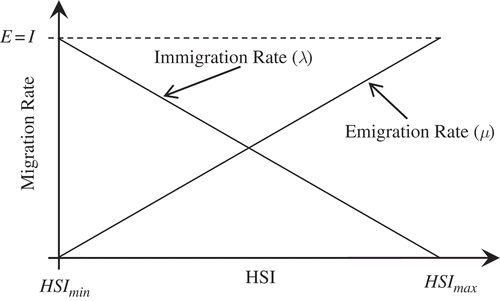
The habitats with a high HSI tend to have a large population of its resident species, which is responsible for more probability of emigration (emigration rate, ) and less probability of immigration (immigration rate,
) due to the natural random behavior of the species. Immigration is the arrival of new species into a habitat or population, whereas emigration is the act of leaving one’s native region. On the other hand, habitats with low HSI tend to have low emigration rate,
, due to sparse population, however, they will have high immigration rate,
. Suitability of habitats with low HSI is likely to increase with influx of species from other habitats having high HSI. However, if HSI does not increase and remains low, species in that habitat becomes extinct, which leads to additional immigration. For sake of simplicity, it is safe to assume a linear relationship between HSI (or population) and immigration and emigration rate and same maximum emigration and immigration probability, that is,
, as depicted graphically in .
The kth habitat values of emigration rate, μk, and immigration rate, λk are given by Equations (1) and (2).
The immigration of new species from high HSI to low HSI habitats could raise the HSI of poor habitats because good solutions are more resistant to change than poor solutions, whereas poor solutions are more dynamic and accept a number of new features from good solutions.
Each habitat, in a population of size NP, is represented by an M-dimensional vector as , where M is the number of SIVs to be evolved for optimal fitness given as
. The following subsections describe the different migration variants of BBO: Standard BBO (Simon Citation2008), Blended BBO (Ma and Simon Citation2011), Immigration Refusal BBO (Du, Simon, and Ergezer Citation2009), and Enhanced BBO (Pattnaik, Lokohare, and Devi Citation2010).
Standard BBO
Algorithmic flow of standard BBO involves two mechanisms, i.e., migration and mutation; these are discussed in the following subsections.
Migration
Migration is a probabilistic operator that improves HSI of poor habitats by sharing features from good habitats. During migration, the ith habitat, Hi (where i = 1, 2, …, N P) uses its immigration rate, λi given by Equation (2), to probabilistically decide whether to immigrate or not. In case immigration is selected, then the emigrating habitat, Hj, is found probabilistically based on emigration rate, μj given by Equation (1). The process of migration is completed by copying values of SIVs from Hj to Hi at random chosen sites. The pseudocode of the migration operator is depicted in Algorithm 1.
Mutation
Mutation is another probabilistic operator that modifies the values of some randomly selected SIVs of some habitats that are intended for exploration of search space for better solutions by increasing the biological diversity in the population. Here, higher mutation rates are investigated in habitats that are, probabilistically, participating less in the migration process. The mutation rate, mRate, for the kth habitat is calculated as Equation (3)
Blended BBO
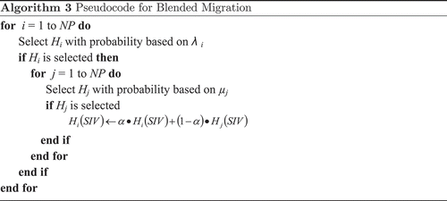
The blended migration operator is a generalization of the standard BBO migration operator and was inspired by blended crossover in GAs (McTavish and Restrepo Citation2008). In blended migration, an SIV value of the immigrating habitat, ImHbt, is not simply replaced by an SIV value of the emigrating habitat, EmHbt, as happened in the standard BBO migration operator. Rather, a new solution feature, SIV value, comprises two components as . Here, α is a random number between 0 and 1. The pseudocode of blended migration is depicted in Algorithm 3.
Immigration Refusal BBO
In BBO, if a habitat has a high emigration rate, that is, the probability of emigrating to other habitats is high and the probability of immigration from other habitats is low. However, the low probability does not mean that immigration will never happen. Once in a while, a highly fit solution might receive solution features from a low-fit solution that might degrade its fitness. In such cases, immigration is refused in order to prevent degradation of HSI values of habitats. This BBO variant with conditional migration is termed Immigration Refusal; its performance with a testbed of benchmark functions is encouraging (Du, Simon, and Ergezer Citation2009). The pseudocode of immigration refusal migration is depicted in Algorithm 4.
Enhanced BBO
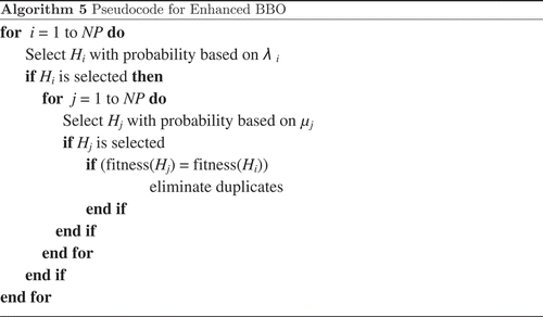
The standard BBO migration operator tends to create duplicate solutions, which decreases the diversity in the population. To prevent this diversity decrease in the population, duplicate habitats are replaced with randomly generated habitats. This leads to increased exploration of new SIV values. In EBBO, a clear duplicate operator is integrated in to the basic BBO algorithm to improve its performance. The migration pseudocode of enhanced BBO is depicted in Algorithm 5.
ANTENNA DESIGN PARAMETERS
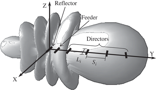
The Yagi–Uda antenna consists of three types of elements: (1) Reflector–largest among all and responsible for blocking radiations in one direction. (2) Feeder–fed with the signal from transmission line to be transmitted and (3) Directors–usually more than one in number and responsible for unidirectional radiations. depicts a typical six-wire Yagi–Uda antenna in which all wires are placed parallel to the x-axis and along the y-axis. The middle segment of the reflector element is placed at origin, x = y = z = 0, and excitation is applied to the middle segment of the feeder element.
Designing a Yagi–Uda antenna involves determination of wire-lengths and wire-spacings in between to get maximum gain and desired impedance, and so forth, at an arbitrary frequency of operation. An antenna with N elements requires 2N − 1 parameters, that is, N wire lengths and N − 1 spacings, that are to be determined. These 2N − 1 parameters, collectively, are represented as a string referred to as a habitat in BBO, given as Equation (4).
where LS are the lengths and SS are the spacing of antenna elements. An incoming field sets up resonant currents on all the antenna elements which re-radiate signals. These re-radiated signals are then picked up by the feeder element, which leads to total current induced in the feeder equivalent to combination of the direct field input and the re-radiated contributions from the director and reflector elements. This makes highly nonlinear and complex relationships between the antenna parameters and its characteristics such as gain and impedance.
MULTIOBJECTIVE OPTIMIZATION
Multiobjective Problems
In single-objective optimization, an optimal solution is easy to obtain as compared to a multiobjective scenario where one solution that could be globally optimal with respect to all objectives may not exist. Objectives under consideration might be conflicting in nature; improvement in one objective could cause declination in other objective(s). One way to solve a multiobjective problem (MOP) is to scalarize the vector of objectives into one objective by averaging the objectives with a weight vector. This process allows a simpler optimization algorithm to be used, however, the obtained solution largely depends on the weight vector used in the scalarization process. A common difficulty with MOP is the conflicting nature of objectives where no solution that could be globally the best for all objectives is feasible. Thus, a most favorable solution is opted, which offers the least objective conflict.
The solution to multiobjective optimization problems result in Pareto-optimal solutions instead of a single optimal solution in every run. There exists a set of solutions that are the best trade-off solutions, important for decision making and often superior to the rest of the solutions when all objectives are considered; however, inferior for one or more objectives. These solutions are termed as Pareto-optimal solutions or nondominated solutions and others as dominated solutions. Every solution from a nondominated set is acceptable because none of them is better than its counterpart. However, final selection of a solution is done by the designer based on nature of the problem under consideration.
Nondominated Sorting
The problem presented in this article of optimizing an antenna design has two objectives, viz. (1) antenna impedance and (2) maximum antenna gain. Desired antenna impedance, i.e., (Re + jIm)Ω, is formulated as a fitness function, f1, given as Equation (5), which is required to be minimized.
Whereas, the second objective of gain maximization is also converted into a minimization fitness function, f2, given as Equation (6):
Suppose every solution, in a swarm of NP solutions, yields and
as fitness values (where k = 1, 2, …, N P), using Equations (5) and (6), that belongs to either a nondominated solution set, P, or a dominated solution set, D. An ith solution in set P dominates the jth solution in set D if satisfies the condition of dominance, i.e.,
and
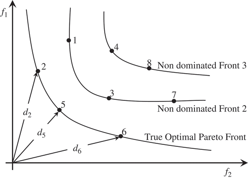
, where both objectives are to be minimized. This condition of dominance is checked for every solution in the universal set of N P solutions to assign it to either P set or D set. Solution members of set P form the first nondominated front, i.e., the Pareto optimal front, and then remaining solutions, those belong to set D, are made to face same condition of dominance among themselves to determine the next nondominated front. This process continues until all solutions are classified into different nondominated fronts, as shown in . Preference order of solutions is to be based on the designer’s choice, however, here, Euclidian distance is determined from origin for every member solution in a nondominated front and are selected in ascending order. The pseudocode of nondominated sorting approach is depicted in Algorithm 6.
SIMULATION RESULTS AND DISCUSSION
As BBO is a swarm-based stochastic optimization algorithm; to present fair analysis, a six-wire Yagi–Uda antenna design is optimized for 10 times using 300 iterations and 50 habitats (particles). The universe of discourses to search optimal values of wire lengths and wire spacings are 0.40λ – 0.50λ and 0.10λ – 0.45λ, respectively. However, crosssectional radius and segment size for all wires are kept constant, in other words 0.003397λ and 0.1λ, respectively, where λ is the wavelength corresponding to frequency of operation, 300MHz. The C++ programming platform is used for algorithm coding, whereas method of moments-based software, Numerical Electromagnetic Code (NEC2) (Burke and Poggio Citation1981), is called, using system command to evaluate antenna designs. Both objectives, gain and impedance, are optimized using two fitness functions, given by Equations (5) and (6).
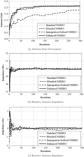
The average of 10 Monte-Carlo simulation runs are plotted to analyze convergence flow while achieving (1) maximum antenna gain, (2) Re = 50Ω, in other words, resistive antenna impedance of 50Ω, and (3) Im = 0Ω, or, zero reactive antenna impedance, in . From the plots, it can be observed that the best compromised solution, during initial iterations, sometimes leads to poor solutions in terms of gain or impedance. However, with increasing numbers of iterations the best compromised solution improves in aggregation that could improve further, if the maximum iteration number is kept high. The best antenna designs obtained during the process of optimization and the average results of 10 Monte-Carlo runs, depicted in , after 300 iterations are tabulated in .
TABLE 1 The Best Antenna Designs Obtained During Optimization and Average Results after 300 Iterations for 50Ω Impedance
CONCLUSIONS AND FUTURE SCOPE
In this article, NSBBO along with different migration variants of the BBO algorithm are investigated for attaining multiple objectives: maximum gain and antenna impedance. The results obtained for multiobjective optimization of the standard NSBBO are found to be better compared to other multiobjective optimization techniques discussed in (Singh, Kumar, H., and Kamal 2010). It can be observed from simulation results that the NSBBO with blended migration presents better convergence flow in terms of achieving gain and only resistive impedance of 50Ω as compared to different variants of BBO over limited 300 iterations. NSBBO has been a good choice for optimizing Yagi-Antenna for multiple objectives and can be tried on other antennas such as antenna arrays as well.
REFERENCES
- Altshuler, E., and D. Linden. 1997. Wire-antenna designs using genetic algorithms. IEEE Antennas and Propagation Magazine 39(2):33–43.
- Baskar, S., et al. 2005. Design of Yagi–Uda antennas using comprehensive learning particle swarm optimisation. IEEE 152(5):340–346.
- Bojsen, J., et al. 1971. Maximum gain of Yagi–Uda arrays. Electronics Letters 7(18):531–532.
- Burke, G. J., and A. J. Poggio. 1981. Numerical electromagnetics code (NEC) method of moments. NOSC Tech. DocLawrence Livermore National Laboratory, Livermore, Calif, USA 116:1–131.
- Chen, C., and D. Cheng. 1975. Optimum element lengths for Yagi–Uda arrays. IEEE Transactions on Antennas and Propagation 23(1):8–15.
- Cheng, D., and C. Chen. 1973. Optimum element spacings for Yagi–Uda arrays. IEEE Transactions on Antennas and Propagation 21(5):615–623.
- Cheng, D. K. 1971. Optimization techniques for antenna arrays. Proceedings of the IEEE 59(12):1664–1674.
- Cheng, D. K. 1991. Gain optimization for Yagi–Uda arrays. IEEE Antennas and Propagation Magazine 33(3):42–46.
- Correia, D., A. J. M. Soares, and M. A. B. Terada. 1999. Optimization of gain, impedance and bandwidth in Yagi–Uda antennas using genetic algorithm. IEEE 1:41–44.
- Darwin, C. 1995. The Origin of Species (2nd ed.), 398–403. New York, NY: Gramercy.
- Deb, K., et al. 2002. A fast and elitist multiobjective genetic algorithm: NSGA-II. IEEE Transactions on Evolutionary Computation 6(2):182–197.
- Du, D., D. Simon, and M. Ergezer. 2009. Biogeography-based optimization combined with evolutionary strategy and immigration refusal. IEEE 1:997–1002.
- Ehrenspeck, H., and H. Poehler. 1959. A new method for obtaining maximum gain from Yagi antennas. IRE Transactions on Antennas and Propagation 7(4):379–386.
- Fishenden, R. M., and E. R. Wiblin. 1949. Design of Yagi aerials. Proceedings of the IEE-Part III: Radio and Communication Engineering 96(39):5.
- Jones, E. A., and W. T. Joines. 1997. Design of Yagi–Uda antennas using genetic algorithms. IEEE Transactions on Antennas and Propagation 45(9):1386–1392.
- Kuwahara, Y. 2005. Multiobjective optimization design of Yagi–Uda antenna. IEEE Transactions on Antennas and Propagation 53(6):1984–1992.
- Li, J. Y. 2007. Optimizing design of antenna using differential evolution. IEEE 1:1–4.
- Ma, H., and D. Simon. 2011. Blended biogeography-based optimization for constrained optimization. Engineering Applications of Artificial Intelligence 24(3):517–525.
- MacArthur, R., and E. Wilson. 1967. The theory of island biogeography. Princeton, NJ: Princeton University Press.
- McTavish, T., and D. Restrepo. 2008. Evolving solutions: The genetic algorithm and evolution strategies for finding optimal parameters. Applications of Computational Intelligence in Biology 1:55–78.
- Pattnaik, S. S., M. R. Lohokare, and S. Devi. 2010. Enhanced biogeography-based optimization using modified clear duplicate operator. IEEE 1:715–720.
- Rattan, M., M. S. Patterh, and B. S. Sohi. 2008. Optimization of Yagi–Uda antenna using simulated annealing. Journal of Electromagnetic Waves and Applications 22 2(3):291–299.
- Reid, D. G. 1946. The gain of an idealized Yagi array. Journal of the Institution of Electrical Engineers-Part IIIA: Radiolocation 93(3):564–566.
- Shen, L. C. 1972. Directivity and bandwidth of single-band and double-band Yagi arrays. IEEE Transactions on Antennas and Propagation 20(6):778–780.
- Simon, D. 2008. Biogeography-based optimization. IEEE Transactions on Evolutionary Computation 12(6):702–713.
- Singh, S., E. Mittal, and G. Sachdeva. 2012a. Multi-objective Gain-Impedance Optimization of Yagi–Uda Antenna using NSBBO and NSPSO. International Journal of Computer Applications. 56:1–6.
- Singh, S., E. Mittal, and G. Sachdeva. 2012b. NSBBO for gain-impedance optimization of Yagi–Uda antenna design. In Information and Communication Technologies (WICT), 2012 World Congress on, 856–860.
- Singh, S., and G. Sachdeva. 2012a. Mutation effects on BBO evolution in optimizing Yagi–Uda antenna design. In International Conference on Emerging Applications of Information Technology (EAIT) 2012, 47–51.
- Singh, S., and G. Sachdeva. 2012b. Yagi–Uda antenna design optimization for maximum gain using different BBO migration variants. International Journal of Computer Applications 58:14–18.
- Singh, U., H. Kumar, and T. S. Kamal. 2010. Design of Yagi–Uda antenna using bio-geography based optimization. IEEE Transactions on Antennas and Propagation 58(10):3375–3379.
- Singh, U., et al. 2007. Design of a Yagi–Uda antenna by simulated annealing for gain, impedance and FBR. IEEE 1:974–979.
- Uda, S., and Y. Mushiake. 1954. Yagi–Uda antenna. Tokyo, Japan: Maruzen Company, Ltd.
- Venkatarayalu, N. V., and T. Ray. 2003. Single and multi-objective design of Yagi–Uda antennas using computational intelligence. IEEE 2:1237–1242.
- Venkatarayalu, N., and T. Ray. 2004. Optimum design of Yagi–Uda antennas using computational intelligence. IEEE Transactions on Antennas and Propagation 52(7):1811–1818.
- Wallace, A. 2005. The geographical distribution of animals. (2nd ed.), 232–237. Boston, MA: Adamant Media Corporation.
- Wang, H. J., et al. 2003. Optimization of Yagi array by hierarchical genetic algorithms. IEEE 1:91–94.
- Yagi, H., 1928. Beam transmission of ultra short waves. Proceedings of the Institute of Radio Engineers 16(6):715–740.

