
ABSTRACT
With the expansion of robotic applications in the industrial domain, it is important that the robots can execute their tasks in a safe and reliable way. A monitoring system can be implemented to ensure the detection of abnormal situations of the robots and report the abnormality to their human supervisors or cooperators. In this work, we focus on developing a modeling framework for monitoring robotic system based on means-end analysis and the concept of action phases from action theory. A circular cascaded action phase structure is proposed for building the model of cyclical robotic events. This functional model provide a formal way of decompose robotic tasks and analyze each level of conditions for an action to be executed successfully. It can be used for monitoring robotic systems by checking the preconditions in the action phases and identifying the failure modes. The proposed method is demonstrated by using a simulated robotic manipulation system. The simulation results demonstrate the feasibility of the developed functional model in finding errors during the execution monitoring.
Introduction
The development of robot technology enables intelligent robot systems to be more and more involved in various areas, such as automatic manufacturing, transportation, agriculture and medication. With the increased flexibility provided by the advanced robot systems, the execution of the robot motion in a safe and reliable way becomes important. The uncertainties from the robot system itself and the environment may cause problems for the robot system and make it fail, and thus impose significant influence on task execution. In order to monitor the behavior of the robot system and be able to identify the causes of failure, the robot system has to be modeled in an appropriate manner which facilitates the supervision system.
The modeling of robot system has been extensively studied in the literature. For example, a robot system is often modeled through approach such as building a quantitative model of physical model of the system using differential equations (Spong, Hutchinson, and Vidyasagar Citation2006). However, these equations can hardly be used as the analysis for the cause of failure is carried out in a more abstract level. Bridging the gap between the quantitative functionalities of the existing control system and the qualitative knowledge needed by an intelligent monitoring system requires a considerable effort. The interpretation of the system from a functional perspective for system supervision is the main focus of the proposed work, especially for the systems with multiple inter-relationships for solving highly complex problems such as multi-agent system or flexible production system.
Functional modeling describes systems with a focus on causality relations between system functions and the operation goals. As pointed out in Lind and Zhang (Citation2014) functional modeling is different from the physical modeling in the sense of different knowledge representation (goals and functions versus behavior) and different information representation (quantitative versus qualitative). Understanding the system and its working environment at different abstraction level is important for an intelligent supervision system. On one side, the modeling of the system at different functional level can serve for different purpose, such as using the lower level for monitoring a control element while using a higher level for monitoring the planned execution. On the other side, the functional modeling provides a systematic way of representing the purpose of complex dynamics systems, which is often implicit in other model representations. In order to understand robotic system at different abstraction levels, the action theory and means-end analysis are used to establish a functional modeling framework. The means-end concept is adopted in multilevel flow modeling (MFM) (Lind Citation1982) to achieve functional modeling of complex process system on multiple abstraction levels. The benefits of using means-end analysis in functional modeling have been demonstrated through the applications of MFM in modeling of nuclear power plants, alarm design and risk analysis (Jing et al. Citation2013; Lind Citation2011; Lind et al. Citation2011). Different from process systems, robotic systems are often discrete and event-based systems. The temporal and sequential property of the system has to be addressed in functional modeling and brings the action theory into the development of the modeling framework for robotic system.
The remainder of this paper is organized as follows: Section “State of the art of modeling within robotics” gives an overview of the related work in the field of robotic system modeling. The key concepts for developing the functional modeling in this work are introduced in section “Action theory.” The proposed modeling framework for robotic system based on means-end analysis and hierarchical model is presented in section “Modeling Framework for Robotic System.” In order to validate the developed modeling framework, a case study is carried out on a pick and place robotic system in section “Case study.” The last section offers concluding remarks and future perspectives.
State of the art of modeling within robotics
In this section, the modeling methodology for robotic system is briefly discussed with regard to its application for monitoring. There are different definitions of monitoring in the literature. In this work, monitoring to detection of abnormal situations of the monitored system. The modeling methods including analytical approach, data-driven approach and knowledge-based approach, and their connections to system monitoring are introduced first. Then, the functional modeling related works for robotic system are studied.
Models for execution monitoring of robotic systems
In order to carry out the execution monitoring, a robotic model providing knowledge required by the supervision system is needed. There are mainly three categories of modeling methods, which can be considered as analytical approach, data-driven approach and knowledge-based approach (Pettersson Citation2005).
With the analytical approach, the physical behavior of the system is described by a mathematical model. The most common approach, the observer-based approach (Frank Citation1990), belongs to this category. This approach contains redundant analytically generated variables. The difference between redundant variables is examined for detecting system deviation in dynamics level. The analytical approach requires a well understanding of the system as well as limited uncertainty of the system.
If the analytical model of the system is not available, which is usually the case for complex system involving high-dimensional input/output data accompanying with inadequate system model, the data-driven approach can be applied. Statistical model is often applied to capture information from the input data, such as using the machine learning technology to create the network between the input data and the output features (Montgomery Citation2007; Pettersson, Karlsson, and Saffiotti Citation2004). The system behavior can be monitored through this approach. For instance, in (Pettersson, Karlsson, and Saffiotti Citation2007) the execution monitoring is realized by classifying observed behavioral patterns into normal or abnormal execution through pattern recognition. For data-driven approach, it is assumed that the characteristics of the data are relatively stable over time.
If the monitoring has to be carried out in different levels of abstraction, the knowledge-based approach can be adopted. The analytical approach and the data-driven approach are combined in this approach to perform hybrid monitoring execution. Causal analysis and expert systems are often used to simulate the behavior of human expert (Jackson Citation1986). An expert system can provide knowledge from first principles to activation level of behaviors. The knowledge is formulated in terms of rules, which are used for fault detection. The modeling approach developed in this work, which studies the system behavior at different functional levels, belongs to the third category.
In this section, the different modeling methods for execution monitoring are discussed. In the next section, some examples related to the functional modeling approach are introduced.
Functional modeling for robotic systems
The robot SHAKEY uses the triangle tables associated with STRIPS to monitor the execution of a plan (Noreils and Chatila Citation1995). The precondition and the postcondition at the operation level are monitored. However, these preconditions and postconditions are not formulated through a generic frame, which is very useful for representing and replanning of complex systems. For example, for some common actions belonging to a certain category, such as ‘‘leaving’’ and ‘‘approaching’’ both belonging to ‘‘moving,’’ a generic definition of preconditions and postconditions could be formalized to facilitate the design of the monitoring system and the reactivity system. In Geib et al. (Citation2006), the object-action complexes (OACs) are used to integrating the high-level planning with low-level robotic control system by identifying the possible actions based on object accordances. Some work focuses on designing robot system through a behavioral network, which associates a behavior with a specific event. It leads to the work of decomposing the robot functions into to different levels of behaviors (Brooks Citation1986; Floreano and Urzelai Citation2000). This approach is limited to the space of behaviors defined in the system, and it results in a system lacking adequate capability dealing with unexpected environmental stimuli. In Albus (Citation1988), NASREM is proposed to describe system with hierarchical levels, where the ‘‘coordinate transform and servoing’’ locates at the lower level while the ‘‘mission planning’’ locates at the higher level.
Another issue related to the monitoring of plan execution is the representation of the world. The evolution of the environment has to be coped with respect to robot’s motion. The new events in the environment are considered in controller design for monitoring the plan execution in (Munson Citation1971). Moreover, the environment stimuli are provided for reactivity of robot system in dynamic environments (Payton Citation1986). However, the relationship among the components in the environments, the robot system and the goal of the task is not well formulated. The world representation is often built in a standalone fashion with the focus on the environmental dynamics itself. Interpreting the relationship between the world and the robot system through systematic approach from the action-role perspective has not been addressed yet in most work. This study combines action theory with means-end and hierarchical model to systematically describe the relationships among different types of actions. The concepts used in this work are described in the following section.
Action theory
This section deals with the theory of action types, which is the idea that all actions can be defined as belonging to a more overall group of actions. For instance, pushing a glass or lifting a table could both be classified as moving an object. Von Wright’s theory of action (Lind Citation2012) is such an analysis, and has identified four basic types of action. Lind has expanded on this theory and identified eight types, by including the role that intervention and omission plays. Action roles describe how the entities that are part of an action are participating in said action.
Von Wright’s theory of action and elementary action types
Von Wright’s theory of action asserts that there are four basic types of action: happen, remain, disappear, and remain absent. These are illustrated using a pTp schema (Lind Citation2012), where T is the action or change, and p is the object or event that this action or change affects. This schema can be observed in .
For example, imagine p being an apple. Eating the apple would be pTp, as the apple disappears, where as putting an apple on a plate could be either
pTp since the apple is in a place it was not before, or pT
p since the apple is no longer where it was.
M. Lind interpretation: interventions and omissions
Morten Lind has expanded upon these, creating eight action types by introducing interventions and Omissions. This is shown in .
Table 1. Von Wright’s basic action types.
Table 2. Intervention and omission action types.
Omissions can be seen as the act of letting something happen, and in that way the basic action types are altered. Interventions seek to change the outcome, which is how the four action types produce, maintain, destroy, and suppress were created (Lind Citation2012).
This can be illustrated by using the same pTp schema as in and including the I in the outcome of the action. The square brackets illustrate what change would have happened without the intervention or omission. The p on the left side of the I represent what happens due to the intervention or omission, and the p on the right side of the I represents what would have happened without.
As such, I can be read as “instead of.” Then, the line pT[pIp] (destroy) reads as “p changes to [not-p instead of p].”
As an example, think of an apple falling from a tree. This would be pT[pIp] (let disappear) in relation to the branch the apple fell from. However, if a person placed their hand under the apple, it could be read as pT[pI
p], as the apple would not disappear, i.e., would be maintained on the branch.
If an apple was plucked from the tree, it would be thought of as pT[pIp], since the apple would have remained on the branch without the intervention, but because of the intervention the concept of the apple being on the branch was destroyed.
The four intervention action types are serving either a promotive function (produce, maintain) or an opposive function (destroy, suppress).
Action roles
For each action, the entities that are engaged in the action can have one of four different roles (Lind Citation2009). The most important roles are the Agent and the Object. The action roles will be capitalized for easy identification.
• The Agent is the entity performing the action.
• The Object is the entity that this action is being performed upon.
• The Helper assists the agent in performing the task.
• The Counter-agent is the entity working against the action taking place.
In a case such as an object being lifted, the Agent would be the entity that does the upwards motion, the Object would be the entity being lifted, the Helper could be a mechanism holding on to the Object, such as glue, and the Counter-agent is just gravity.
While the Agent and Object are always present in an action, a Counter-agent and Helper are not always present or easily identifiable.
In a sequence of events, the roles may be changed from one action to another. That is, the Agent of the initial action might be the Object, Helper, or Counter-agent of the second action.
Action phases
Action Phases describe the conditions for a successful action, and are provided in (Lind Citation2010). Each action type contains its own action phases that need to be fulfilled in order to complete the given action.
Figure 1. Action phases.
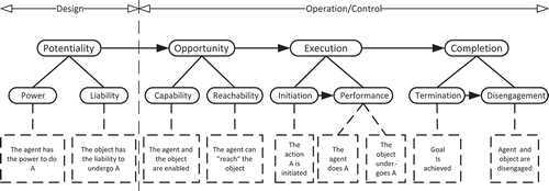
Potentiality describes the capability that the system should have for completing the desired tasks. During design, the potentiality of an action should be ensured. As can be seen from the figure, potentiality is the only field under Design, where the remaining fields can be grouped under Operation. It is different from Opportunity in that the system must be designed with the ability to complete said task, whereas Opportunity is the possibility of the task being completed due to circumstances. Examples of potentiality can be the strength of a robotic arm being large enough to lift an object, a camera being able to detect infra-red light, or a person having the knowledge to operate a piece of machinery.
Potentiality is achieved by ensuring that the object has the liability (Rom Citation1975) to undergo the event (undergo change), and the agent has the power to perform the event (perform change). In this way, liability and power are two sides of the same coin, and one cannot exist without the other. For example, a hammer smashing a plate (Rom Citation1975). For this action to be possible, not only must the hammer be strong enough to smash the plate, the plate must also be fragile, i.e., have the liability, to be smashed. Another example could be a robot having the strength to bend a metal object of a certain size, but if the object is made of wood it is unbendable, and thus the object does not have the liability to be bent, just as the robot does not have the power to bend it.
Opportunity is guaranteed by ensuring the capability and reachability of an agent and object. Both need to be “enabled” and the agent also needs to be physically able to complete its task. Considering a robotic arm, if it could be strong enough to lift the object, it is the agent of, thereby having the potentiality for completing the action. But if it is in another room than the object (and unable to transport itself from that room to the object), it lacks the opportunity to complete the action. Other examples of opportunity are, using the previous examples, that the camera is turned on, and turned the correct direction, and that the person is awake and knows where the machinery that needs operating is placed.
Execution is a two-part process that begins with initiation and is completed by the task being performed. In some cases execution can be simply the triggering of an event, in other cases the performing part is more cumbersome, such as in maintaining a situation for an extended period of time.
An action can be initiated by the flip of a switch, or in the case of a person performing a jump, the initiation would be the straightening of the legs from a crouching position, which would result in upwards motion of the body. The performing part in this case would be the follow-through, of continuing to tighten the muscles to propel oneself upwards. Another example could be in the case of a maintenance action, where the performance portion of the action would have a much longer duration.
Completion is achieved when the goal of the action is achieved. This could be a short instance in time such as a picture being taken and saved to the camera memory, or it could be a much longer time, such as in a maintenance case where completion would be an ongoing process.
Action Phase theory ties in with the concept of action roles, since the roles are the entities which ensure that all the phases of the action can be completed. The role of counter-agent is important to consider in the design phase of a system, as it could be used to ensure potentiality. For instance, if the counter-agent is gravity, potentiality is ensured by having an agent with the strength to counter the force of gravity.
Modeling framework for robotic system
Section “Models for execution monitoring of robotic systems” explains the relevance of using action theory as the foundation for establishing a functional modeling framework, which can be used to represent robots actions systematically. Based on this discussion, a modeling framework is developed in this section.
Means-end analysis and hierarchical model
A hierarchy is commonly understood as a type of arrangement of items in which the items are represented as being above, below or at the same level. The concept has been brought into the field of cognitive engineering as an approach to organizing functional concepts. (Brooks Citation1986) developed the abstraction hierarchy (AH), to utilize the different levels of means-end abstractions to represent complex system functions in a hierarchical way, which, proved by various empirical studies, is coherent with the human operators’ fault finding strategies in the control room.
AH organizes the functional concepts related to a complex system into five different levels: functional purpose, abstract function, generalized function, physical function and physical form. Thus it can be used for system analysis to navigate through different levels to find the appropriate abstraction to fit for the application. The core of AH is the means-end dependencies between the five levels, and it gives AH the facility to handle functional complexity.
In robotic systems, complexity also poses similar challenge for system analysis. However, the complexity of analyzing robot behaviors lays more in the actions of the agents and transformations of the objects. Therefore, the means-end hierarchy is adopted to analyzing the robotic actions.
An example of means-end hierarchy was developed to show how it can apply to robotic actions. The model is developed for the pick up and place task of a robot arm. The object is grabbed from a conveyor belt and placed onto a goal position. The levels of abstraction were, in descending order: tasks, activities, actions, roles, and preconditions. The model is shown in .
Figure 2. Hierarchical means-end model of the robotic system.
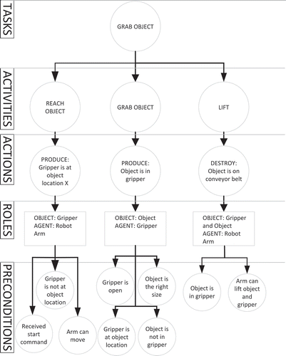
• Tasks: the overall goals that need to be achieved by the robot system.
• Activities: the breakdown of a task into more specific sub-goals that need to be achieved in sequence to complete the task.
• Actions: activities can be further decomposed into a set of actions that of the four basic action types.
• Roles: the requirement for the physical components to serve their individual action roles.
This model helped in identifying the separate events as well as the preconditions for these events to be successful.
A hierarchical model of a system is useful for understanding how the system works. However, it is also incomplete for modeling the robot system, as there is no indication in the model that how each block in the model can influence other blocks beyond one thread of means-end dependency.
Modeling of action phases
Using the basic action types described in section “Models for execution monitoring of robotic systems,” it is possible to describe the robotic system events. And by applying the means-end analysis, one can trace the functional requirements for individual activities. The action role analysis in the means-end model also looks at the components and how they act in an event.
In order to create a model that can describe the actions of the robotic system, the concept of action phases introduced in section “Models for execution monitoring of robotic systems” was used. Action phases introduce the temporal element in a means-end model, thus it creates the dependency connection between different activities. Then, the hierarchical structure of the means-end model became a action network. Since the end of one action is often the precondition for the start of another, it was considered logical to chain these actions together, so that the completion of, for example, the gripper opening, would satisfy the opportunity criteria of the reach object action of the gripper.
is the first attempt at an analysis of the robotic system with a focus on action phases. The actions are chosen to follow the previous means-end model. In order to reduce the visual clutter, the content of the action phase boxes have been reduced to brief description. The arrows connecting the action phase boxes indicate how the completion of one action becomes the opportunity of another action.
Figure 3. Cascaded action phase diagram.
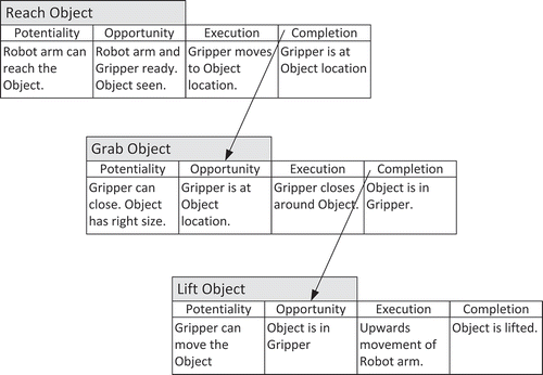
The application of the action phases theory revealed a great deal of preconditions in a systematic way that had not been previously considered. In the hierarchical model, preconditions are included. However, these preconditions are few and vague compared to the preconditions outlined in this section. This is due to the distinction between preconditions of opportunity and potentiality. Having to think about an action in terms of the opportunity to perform that action and the potentiality for that action to be performed, reveals more preconditions than that are revealed when simply thinking about “what needs to be in place for this action to take place?” This revealing of preconditions is also part of the reason why a structured way to think about actions is valuable.
Documenting actions as separate events does not leave room for the intended outcome of the system. A sequence of successful events does not automatically result in the intended outcome. For instance, if the object is the wrong size or weight, all the actions that the robot system perform might be successful, but the object would be impossible to pick up by the robot arm, during, or after the robot attempts to lift it off the conveyor belt. This can be avoided by analyzing the potentiality and opportunity of each action phase while designing the robot system, as this could motivate the designers to implement monitoring systems for the power, liability, capability and reachability of each action phase.
Modeling framework
When examine robotic systems commonly used in the industry, three distinct types of activity can be observed. The first type of activity consists of a series of sequential actions that has a start triggering event and an end point marking the finish of the activity. The end result is used to evaluate the successfulness of the activity. The previously used example can be categorized as a sequential activity, see ).
Figure 4. Three different types of activity: (a) sequential activity; (b) cyclical activity; (c) facilitating activity.
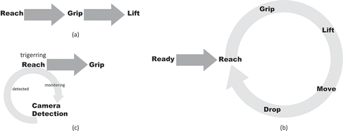
In the robotic systems for manufacturing lines, for a single robot unit, the activities are often repetitive. And the end of the activity is often to resume the initial state just to repeat the previous activity. This type of periodical behavior can be categorized as cyclical. Consider the robot system that has to pick up objects repeatedly from one location to another; this activity becomes cyclical rather than sequential, see ). This type of activity is often evaluated by using the collective result instead of a single run of the actions.
There is also a third type of activity that has less to do with motion but more with facilitate robot system to perform. This type of activity does not change the form or the location of the object, but exists to provide pre-conditions for other actions to be performed during other activity. One example can be laser scanner for testing the availability of the object in order to trigger the robot arm to move toward the object, see ). The facilitating activity only exists when other activity provides an objective.
This work focuses on the modeling of robotic system executing cyclical activity with a facilitating triggering. The development of the modeling framework is conducted in section “Case study” through a case study.
Monitoring system based on the developed model
A model developed using the methodology outlined previously in this section can be useful in many phases of system development and utilization, such as design, monitoring, diagnosis and planning.
A system can be designed based on a functional analysis of the desired tasks to be performed. In a finished system, the model can be used for monitoring the system and registering if anything goes wrong by checking preconditions to actions. This in turn could be useful for diagnosing why an error occurred, and even planning how to move forward and either bypass the error, correct the error, or stop the system.
The monitoring system tracks the robotic system for detecting deviations. A monitoring system can be developed based on the modeling framework introduced in this section. Because the actions in the modeling framework are specified by using a defined form, knowledge based system can be developed to reason about the actions’ means-end dependencies.
The knowledge base (Giarratano and Riley Citation1998) is applied for the implementation of the monitoring system. It is made up of the templates, the main model rulebase, and the error rulebase. The details about the implementation is explained and discussed in section “Case study.”
Case study
In this section, a case study is carried out to develop the modeling framework for robotic system executing cyclical actions. First, the robotic platform is introduced. Then, the modeling framework is proposed with the given robotic system. A monitoring system is developed based on the established model. Finally, simulated signals are generated for testing the monitoring system. The details of these steps are described in the rest of this section.
The robotic system platform
The robot system used in this case study consists of a 6-joint robotic arm with a two-finger gripper, a camera system, and a conveyor belt. They will throughout the report be referred to as “components” of the whole system. It is intended to be part of a slaughterhouse process, where its specific function is for the robotic arm to lift a slab of meat off a conveyor belt and move it to a collection of meat-hooks on a pole, referred to from here on as the Christmas tree or CT. The meat hooks will be referred to as a CT spike.
The platform of the robotic system is shown in ).
Figure 5. The robotic system and its functional block diagram.
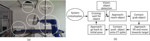
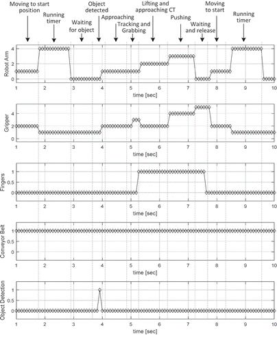
The robot control box, the camera and the gripper are connected to a PC where the control algorithm is implemented. The robot control box is used for communicating with the robot arm. The conveyor belt can be turned on/off manually through a standalone control box. The function of the system is depicted in ). The system starts with an initialization process, which initializes the gripper, starts the camera system, and enables the communication between the control PC and other components of the system. For this step, a timer is applied to indicate the end of the procedure. Once the timer has finished, the meat can be placed on the conveyor belt. The image processing algorithm detects the meat as soon as the meat appears in the camera’s field of view. Then, the position and orientation of the meat will be sent to the controller. With this information the controller calculates the path from the start position to the position where it has to grab the meat. The robot arm is then triggered to reach for the meat, and the gripper is closed to grab the meat. Having lifted the meat off the conveyor belt, the robot arm moves the meat toward a CT spike, and pushes the gripper down, impaling the meat on the spike. Once the gripper has reached the base of the spike, the gripper opens. Finally, the robot arm moves back to the start position, being ready to move again if another piece of meat is detected. It has to be mentioned that another timer is applied when the robot arm is waiting for the next meat. The timer is started again every time the arm moves back to the initial position. The purpose of using this timer is to indicate the waiting time. It can be used for presenting a warning message to the operator if a long period of time has elapsed.
According to the platform, the following five signals can be measured and provided for the control system:
the state of the robotarm
the position of the gripper,
the distance between the gripper fingers,
whether the conveyor belt is on or off,
image sequence from the camera at 30°Hz, which is the input of image processing algorithm.
As only five signals are assumed to be known, it means some preconditions for events must be assumed. For instance, for the type of gripper used in this system it cannot register an object in hand when the fingers are not moving. Therefore, it is assumed that the meat stays in the gripper when it is lifted off the conveyor belt.
Functional modeling of the robotic system
Following the discussion in sections “models for execution monitoring of robotic systems” and “Modeling framework for robotic system,” the hierarchical means-end analysis and cascaded action phase diagram are utilized for the modeling of the robotic system introduced in section “The robotic system platform.”
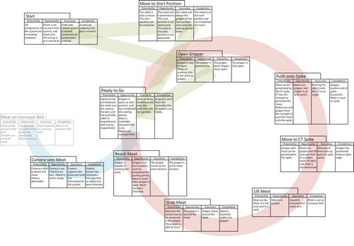
According to the hierarchical means-end model depicted in and the cascaded action phase diagram in , the following steps have to be identified for creating the model: identify tasks, identify actions, identify action phases. Then, it has to identify cascade action chain. Here, the action should be chained together by identify which actions need to be completed in order to trigger the opportunity requirements of other actions. Finally, by explicitly identifying the initialization, triggering and circular processes of the system, and adding the accompanying node points, the model is established, see also the . The system consists of four parts:
Figure 6. The functional model of the robotic system.
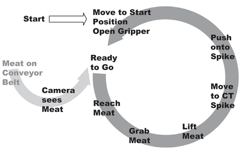
initialization: it happens only once when the system starts up. The components such as robot arm and gripper are initialized during this step. When this step is completed, the gripper is open and moved to the start position.
triggering: the camera part represents the meat detection through image processing. Once the meat is detected, the position and orientation of the meat on the conveyor belt is sent to the controller. This part is independent from the rest of the system, as it will register an object regardless of which action the system is carrying out at the moment.
cyclical actions: every time a new object is detected, this circle is followed and completed. In order to repeat the activity when new object appears, the system has to resume the initial state after it finished the actions on the circle
node point: the ‘‘Ready to go’’ is a state where the system waits for a trigger.
A more detailed version of the developed model given in Appendix 1, where the action phases for each step is described.
Monitoring system for robotic system
In order to build the monitoring system for detecting the deviation of the system, the knowledge base consisting of the main model rulebase and the error rulebase is constructed, see . The main rulebase contains the rules that check the state of the robotic system, while the error rulebase contains the rules for error detection. Moreover, three templates are designed to describe the status of components, the state of the system and error message. A simulated robotic system, which completes the task in the platform shown in , is created to generate the signals for testing the monitoring system. The signals are saved to the working memory which is accessible by other blocks. The system state/fact and the error message are presented to operators as well as logged into a file through the output block.
Figure 7. The knowledge rulebase for monitoring of the robotic system.
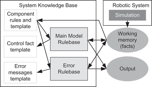
The monitoring system is implemented in C Language Integrated Production System (CLIPS) which is a programming language used for the development of expert system (Giarratano Citation2002)The templates, the rulebase, the simulated signals as well as the communication among those blocks are described in this section.
Templates
Following the CLIPS syntax of templates, three templates are created. The component template is updated by the simulation. Typically the simulated robotic system asserts the updated component values as facts to the working memory, which triggers the component rules to update the component templates. For each component in the system, a component template is created, including component templates for the robotarm, the gripper, the fingers of the gripper, the detection by camera and the conveyor belt.
The control fact template tracks the state of the robotic system and updates the state of the system triggered by the main rulebase. The error message template is used to set whether errors have been detected or not. If an error is detected by the error rulebase, the error template registers the error in the error message. It has to be mentioned that the template is not changed, but the values of the variables they contain are updated through the rulebase.
Main model rulebase
The main model rulebase checks the robotic system states according to the functional system model. As shown in , the main rulebase reads the component information from the component block and the facts from the working memory respectively. It asserts new facts if the system state switches from one state to another. The control fact template is modified accordingly to capture the update of the system state. The new fact is also saved to the working memory, so that the rest of the system knows which state the robotic system stays.
The main rulebase consists of three types: the initialization rules, the triggering rules and the circular process rules, shown in ).
Figure 8. The main rules and error rules for the robotic system.
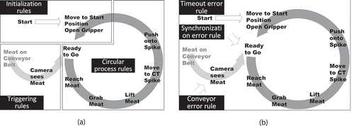
Initialization process rules are the rules that are related to the initialization of the system, including moving the robot to the initial pose and opening the gripper. The triggering rules are rules that are activated when an object is registered by the vision system. The circular process rules are the rules for checking the activity of the circular process. Once the system is ready and an object is registered the first rule of the circular process is triggered.
Error rulebase
The rules of error monitoring are the rules checking if the errors are present. Error templates are crated for setting or resetting error messages easily. Three types of error are chosen to test the monitoring system: the synchronization error, the timeout error, and the conveyor belt error, see ).
The synchronization error refers to the problem caused by the synchronization issue among different components. For example, if an object is detected on the conveyor before the system is ready, an error message will be shown to the operator. The timeout error rule is used to record the time elapsed since the system enters a new state. It checks whether the robotic system progresses as planned, or is possibly stuck somewhere. The rule for detecting conveyor belt error is used to monitor the status of the conveyor belt. The rule throws a message if the conveyor belt stops moving.
The main model rules and the error model rules run in parallel. The error rules do not influence the main system monitoring, but simply throw an alert by writing to the screen and a file.
Simulation and results
The monitoring system developed from the functional system model is implemented in this section for validation. The robotic system is used to generate signals for testing. As described in section “The robotic system platform” five signals are assumed to be available for monitoring system, see also . Each signal has different values denoting different status of the component. Most of the vales in this table are self-explanatory. For the robotarm and the gripper a short explanation is needed. The moving state of the robot arm is whenever the arm is moving but neither lifting nor pushing. NotReady is activated after the robotarm is moved to the start position, but before the timer for moving runs out. For gripper NotStart is when the gripper should be moved to the start position by the robotarm. Start is when the Gripper is at the start position. Object is when the gripper is tracking the object. CTbegin and CTend are active when the gripper is at the spike point and the spike base, respectively. shows an example of simulated signals for the components during the pick-and-place task. It is assumed that each signal is updated every 0.1°s.
Table 3. Simulated signals for testing monitoring system.
Figure 9. Simulated signals for a successful execution of the pick-and-place task.
Test 1: detection of synchronization error
In order to detect the synchronization error, the simulated signals shown in ) are used for testing. In this scenario the system is supposed to start up the initialization process. However, the camera detects the object before the robot arm finished the timer, which lasts 1.2 s in the simulation. Therefore, the system is not ready for manipulating object, which means the object will not be processed by the robotarm correctly. In this case, an error message should be thrown to the screen by the monitoring system. A screen snapshot is shown in ).
Figure 10. Simulated signals for detection of synchronization error and screen snapshot after test.
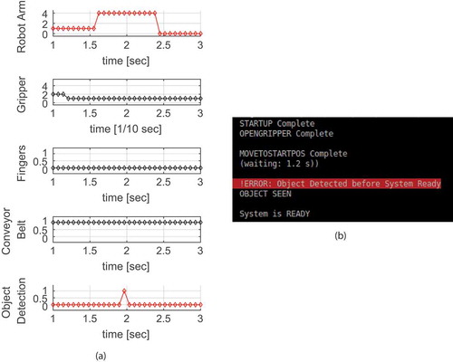
After the completion of each step, a message is printed to update the state of the system on the screen. When the object is detected before the system is ready, the monitoring system throws an error message to the interface.
Test 2: detection of timeout error and conveyor belt error
Similarly to test 1, the simulated signals shown in are generated to test the detections of conveyor belt error and the timeout error.
Figure 11. Simulated signals for the detections of conveyor belt error and the timeout error.
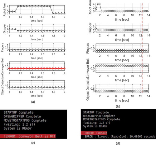
As shown in ), the signal of the conveyor belt is set to ‘‘0,’’ which means the conveyor belt is stopped from moving. By running the monitoring system, the error is detected and the error messaged is printed to the screen, as shown in ).
The signals given in ) describe the scenario where the system has been waiting for the object for too long time. A threshold of 10 seconds is applied. The error message is printed when the object does not show up within 10 seconds, as shown in ).
The simulation in this section demonstrates the usefulness of the monitoring system for error detection.
Conclusion
In this work the framework of function modeling for robotic system is developed through a case study on a known robotic system. The action theory and the means-end hierarchical analysis are studied and applied to generate the modeling methodology. The analysis of the action phases is useful for identifying preconditions, thus useful for locating the error in the robotic system. The expert system CLIPS is used to implement the developed monitoring system based on the functional model. The implementation of the model covered all the model states. Three error types are chosen for testing the monitoring system. The simulation results demonstrate that the monitoring system can successfully detect the errors and communicates to operators through error messages on the screen.
The future work is concerned with testing the developed monitoring system on the real robotic system and expanding the error detection system, in order to develop a diagnosis system, and furthermore a planning system that would be able to guide the robotic system back to working smoothly in the event of errors.
A complete functional model
Simulated signals for the detections of conveyor belt error and the timeout error.
References
- Albus, J. S. 1988. System description and design architecture for multiple autonomous undersea vehicles, Vol. 1251. US Department of Commerce, National Institute of Standards and Technology.
- Brooks, R. 1986. A robust layered control system for a mobile robot. IEEE Journal on Robotics and Automation 2 (1):14–23. doi:10.1109/JRA.1986.1087032.
- Floreano, D., and J. Urzelai. 2000. Evolutionary robots with on-line self-organization and behavioral fitness. Neural Networks 13 (4):431–43. doi:10.1016/S0893-6080(00)00032-0.
- Frank, P. M. 1990. Fault diagnosis in dynamic systems using analytical and knowledge-based redundancy: A survey and some new results. Automatica 26 (3):459–74. doi:10.1016/0005-1098(90)90018-D.
- Geib, C., K. Mourao, R. Petrick, N. Pugeault, M. Steedman, N. Krueger, and W. Florentin. 2006. Object action complexes as an interface for planning and robot control. IEEE RAS International Conference on Humanoid Robots, University of Genova, Genova, Italy.
- Giarratano, J. 2002. Clips: User guide version 6.20.
- Giarratano, J., and G. Riley. 1998. Expert systems: Principles and programming, 3rd ed. PWS.
- Jackson, P. 1986. Introduction to expert systems, Brooks/Cole Publishning Co.
- Jing, W., L. Zhang, W. Liang, and H. Jinqiu. 2013. A novel failure mode analysis model for gathering system based on multilevel flow modeling and hazop. Process Safety and Environmental Protection 91 (1):54–60. doi:10.1016/j.psep.2012.02.002.
- Lind, M. 1982. Multilevel flow modelling of process plant for diagnosis and control.
- Lind, M. 2009. Levels of execution. Unpublished lecture note for course 31372, May.
- Lind, M. 2010. Foundations of functional modelling for engineering design concepts of means and ends. Unpublished lecture note, April.
- Lind, M. 2011. An introduction to multilevel flow modeling. Nuclear Safety and Simulation 2 (1):22–32.
- Lind, M. 2012. Promoting and opposing: A semantic analysis of von wright’s action types. Unpublished lecture note, December.
- Lind, M., H. Yoshikawa, S. B. Jørgensen, M. Yang, K. Tamayama, and K. Okusa. 2011. Multilevel flow modeling of monju nuclear power plant. Nuclear Safety and Simulation 2 (3):274–84.
- Lind, M., and X. Zhang. 2014. Functional modelling for fault diagnosis and its application for npp. Nuclear Engineering and Technology 46 (6):753–72. doi:10.5516/NET.04.2014.721.
- Montgomery, D. C. 2007. Introduction to statistical quality control. Hoboken, New Jersey, United States: John Wiley & Sons.
- Munson, J. H. 1971. Robot planning, execution, and monitoring in an uncertain environment. IJCAI, Proc Int Jt Conf Art Intel, London, 338–49.
- Noreils, F. R., and R. G. Chatila. 1995. Plan execution monitoring and control architecture for mobile robots. IEEE Transactions on Robotics and Automation 11:255–66. doi:10.1109/70.370506.
- Payton, D. 1986. An architecture for reflexive autonomous vehicle control. Robotics and Automation. Proceedings. 1986 IEEE International Conference on 3, 1838–45, IEEE.
- Pettersson, O. 2005. Execution monitoring in robotics: A survey. Robotics and Autonomous Systems, IEEE. 53 (2):73–88. doi:10.1016/j.robot.2005.09.004.
- Pettersson, O., L. Karlsson, and A. Saffiotti. 2004. Model-free execution monitoring in behavior-based mobile robotics. Örebro universitetsbibliotek.
- Pettersson, O., L. Karlsson, and A. Saffiotti. 2007. Model-free execution monitoring in behavior-based robotics. IEEE Transactions on Systems, Man, and Cybernetics, Part B (Cybernetics) Oxford: Blackwell, 37 (4):890–901. doi:10.1109/TSMCB.2007.895359.
- Rom, H. 1975. Causal Powers: Theory of Natural Necessity, 1st ed. Rowman and Littlefield.
- Spong, M. W., S. Hutchinson, and M. Vidyasagar. 2006. Robot modeling and control, Vol. 3. New York: Wiley.