
 ?Mathematical formulae have been encoded as MathML and are displayed in this HTML version using MathJax in order to improve their display. Uncheck the box to turn MathJax off. This feature requires Javascript. Click on a formula to zoom.
ABSTRACT
This article designs a novel adaptive trajectory tracking controller for nonholonomic wheeled mobile robot under kinematic and dynamic uncertainties. A new velocity controller, in which kinematic parameter is estimated, produces velocity command of the robot. The designed adaptive sliding mode dynamic controller incorporates an estimator term to compensate for the external disturbances and dynamic uncertainties and a feedback term to improve the closed-loop stability and account for the estimation error of external disturbances. The system stability is analyzed using Lyapunov theory. Computer simulations affirm the robustness of the designed control scheme.
Introduction
Control of the two-wheeled nonholonomic mobile robot has attracted a lot of attention last decades since it has a widespread potential applications in several fields (e.g., mining, transportation, and planetary). These applications require mobile robot to be able to track a specified path stably. Designing a controller that guarantees trajectory tracking and robustness against modeled and unmodeled dynamics is a big challenge for engineers.
Many researches are conducted to develop adaptive controllers to control the motion of mobile robot with disturbances and uncertainties (Wang, Fukao, and Adachi (Citation2002), Onat and Ozkan (Citation2015), Dong, Xu, and Huo (Citation2000)). For these methods, a linearly parameterized model of the system is required, in which the computation of the regression matrix introduces a tedious analysis. The problem of computation burden can degrade the control performance.
Alternatively, intelligent control based on neural networks (Singh and Parhi (Citation2011), Gao et al. (Citation2014), Ye (Citation2015), Hoang and Kang (Citation2016)) becomes an interesting method to control robot system using function approximation. In Singh and Parhi (Citation2011), the authors developed neural networks controller to make the robot navigates in a real environment. The robots have to find optimal path and avoid obstacle. In Gao et al. (Citation2014), the authors presented neural networks based on a radial basis function to remove the effect of wheel slippage that affects the robot in its navigation in uneven terrain. In Ye (Citation2015), the authors used two neural network controllers to tune the velocity and the orientation angle of the robot, for solving the trajectory tracking problem. An adaptive neural network with online updating law has been presented to control the motion of the mobile robot, when disturbance force and wheel slip occur (Hoang and Kang (Citation2016)). However, neural networks strategy has many disadvantages such as involved structure, slow convergence, and difficulties in selecting the appropriate network.
Sliding mode control is widely utilized to control robotic system as it has interesting features such as ability to deal with uncertainties, fast response, and so on (Matveev, Teimoori, and Savkin (Citation2011), Yang et al. (Citation2012), Matveev, Teimoori, and Savkin (Citation2012), Gracia, Garelli, and Sala (Citation2013)). However, chattering phenomenon caused by the discontinuous function excites unmodeled high-frequency dynamics and deteriorates the system performance. Moreover, selecting a large value of the switching gain in the sliding mode control to ensure the effectiveness of the control system may cause severe solicitations in the control inputs and increase the chattering phenomenon.
In order to overcome these difficulties, Liu, Yu, and Zhang (Citation2009) proposed a sliding mode controller based on neural networks to accomplish the tracking control of a mobile robot in the presence of disturbances. They used backstepping techniques to find out velocity output and combined sliding mode control and radial basis function neural networks to derive the necessary input torques. In Pamosoaji, Cat, and Hong (Citation2014), the authors designed a sliding mode controller integrated with radial basis function neural networks to resolve the problem of obstacle avoidance of an uncertain wheeled vehicle. Remarkable robustness against uncertainties was obtained. However, integrating sliding mode control with neural networks in the control law makes the control structure too complicated and computationally expensive. Adaptive sliding mode control was addressed in Chen et al. (Citation2009) and Asif, Khan, and Cai (Citation2014). The idea is to use boundary layer approach to reduce the chattering phenomenon and adaptive switching gain to compensate for disturbances. It should be pointed out that the aforementioned controllers are concerned with the case that the upper bounds of disturbances are known.
The problem of disturbance estimation, in which the information of boundary disturbance is no longer needed, has been addressed in Arab and Fateh (Citation2015), Xin et al. (Citation2016), and Yue et al. (Citation2012). These aforementioned works motivate as to propose a new adaptive sliding mode controller for the tracking control of a mobile robot affected by disturbances and uncertainties. The main contribution of this work is to give fast and accurate compensation of parameter variation and external disturbances, even if the upper bounds of disturbances are unknown. The proposed controller consists of three main parts: an equivalent control law, an adaptive term to estimate external disturbance torques and compensate for both uncertainties and disturbances, and a feedback term to ameliorate the closed-loop stability of the system. The difference between this work and the existing works designed with disturbance estimation can be summarized as follows:
• The controllers developed in Xin et al. (Citation2016) and Yue et al. (Citation2012) use the boundary layer approach in the control law. This can reduce the chattering phenomenon, but it cannot remove it completely. In our approach, the chattering phenomenon is suppressed, thanks to the developed continuous control law using the fundamental of sliding mode control.
• The robust adaptive controller developed in Huang et al. (Citation2016) relies on linearly parameterized model and uses adaptive control to estimate parameters and disturbances. Large control gain is required to achieve good performance of the controller. This may increase the adaptation time and the computation burden. Meanwhile, our proposed method guaranties efficient compensation of uncertainties and disturbances without the need of a linearly parameterized model of the system. This makes our approach more suitable in controlling robotic system, especially when fast convergence is needed.
• In Arab and Fateh (Citation2015), the authors addressed the problem of disturbance estimation using fuzzy logic control. The notable disadvantage of fuzzy logic control is the difficulties in choosing the membership function as well as fuzzy rules, especially when the system is too complicated.
The outline of the rest of this article is arranged as follows: Section “Model of a Nonholonomic Mobile Robot” is devoted to kinematic and dynamic modeling of the mobile robot with nonholonomic constraints. Section “Problem Formulation and Controller Design” presents the controller used in solving the trajectory tracking problem. In Section “Simulation Results,” simulation results are presented to illustrate the efficacy of the designed adaptive sliding mode controller. Conclusions are given in Section 5.
Model of a Nonholonomic Mobile Robot
The nonholonomic wheeled mobile robot presented in is composed of two actuated wheels and a free front wheel.
Figure 1. Mobile robot with two actuated wheels
The kinematic and dynamic models of a nonholonomic system are illustrated by the following equations:
where denotes the position and orientation of the robot,
is the vector of linear and angular velocities, respectively,
defines the input torques applied to the wheels,
defines the external torque disturbances,
is symmetric definite positive inertia matrix,
defines the centripetal and Coriolis matrices, and
defines the input transformation matrix. These matrices are the same as given in Das et al. (2012):
In the above expressions, defines the distance that separates the center of mass
and
the middle point between the two actuated wheels,
defines the radius of the wheel,
represents the half width of the vehicle,
and
, where
and
are the mass of the body and the wheel, respectively,
and
are the moments of inertia of the body about the vertical axis and the wheel about the wheel diameter, respectively.
The dynamic system (2) in the absence of external disturbances can be rewritten as follows:
where .
Problem Formulation and Controller Design
The control system described in shows how the mobile robot can track a desired trajectory when parameter variations and disturbances affected the system.
Figure 2. Description of the control system
Based on kinematics of the system (1), a velocity controller is produced, such that the actual mobile robot posture
converge to the desired posture
(i.e.,
). The update law is used to estimate for the kinematic parameter
.
Based on dynamics of the robot (2), a torque controller is produced such that the actual velocity of the vehicle converge to the velocity command
(i.e.,
).
The estimator term is used to estimate for external disturbances to achieve better compensation of both disturbances and uncertain dynamic parameters.
Design of the Adaptive Velocity Controller with Kinematic Uncertainty
In this section, we aim to generate a velocity output such that the position tracking errors between the actual mobile robot and the reference one converge to zero. Let us define the configuration of the reference robot:
where defines reference velocity vector. The posture tracking error can be expressed as follows:
The derivative of EquationEquation (5)(5)
(5) is given by
Let us define the following Lyapunov function:
we note that is the estimation error of the distance
, which is the difference between
and its estimate
. The derivative of EquationEquation (7)
(7)
(7) is as follows:
Then, the velocity controller is designed as follows:
with and
are positive constants. And the update law for
is
Then, EquationEquation (8)(8)
(8) becomes
Remark 1. Compared with the kinematic controllers (Asif, Khan, and Cai (Citation2014); Chen et al. (Citation2009); Yue et al. (Citation2012)), our proposed adaptive velocity controller is able to estimate kinematic parameter and uses reduced control gains.
Design of the Adaptive Sliding Mode Torques Controller with Dynamic Uncertainties
This section is dedicated to produce the necessary torque, such that the actual velocity of the system converge to the velocity output
.
The velocity error is represented by
We select a proportional–integral–derivative (PID) sliding surface in function of the velocity error:
where is a definite positive matrix. Its derivative can be obtained as follows:
If we substitute EquationEquation (3)(3)
(3) into EquationEquation (13)
(13)
(13) , we obtain
In order to put the system on the sliding surface, we assume that , then we obtain
It is important to emphasize that external disturbances and uncertainties may affect the robot in real applications. Accordingly, the dynamic model (3) can be transformed into
where
Remark 2. The vector of external disturbances applied on the wheels may be caused by instantaneous collision with an obstacle, navigating on uneven terrain or vibration of the driving motors.
Remark 3. The vector of uncertainties is assumed to be bounded and may contain parametric uncertainties and nonparametric uncertainties. Parametric uncertainties are caused by inaccurate measurement of the mobile robot parameters, for example, the mass and the moment of inertia. Nonparametric uncertainties may be caused by unmodeled dynamics of the vehicle, for example, passive wheel and viscous friction.
In order to deal with disturbances and parameter variations, the discontinuous control law is given by
where designs a positive constant (greater than the bound of the vector related to disturbances and uncertainties), which must be a priori known. And
designs signum function. Then, the control law is
The gain must be chosen in an appropriate way to ensure good trajectory tracking when the dynamic parameters of the robot are unknown and the external disturbances affect the system.
In the application of the control law (19), the uncertainty bound parameter should be a priori known. Selecting this bound is too difficult and needs a trade-off between chattering and performance. A large value of this parameter ensures good performance but may increase the chattering phenomenon. Meanwhile, a small value of this parameter may increase tracking errors and leads to the instability of the system.
The task of the proposed adaptive sliding mode torque controller is to compensate for parameter variations and external disturbances without using information of the uncertainty bound parameter. To accomplish this, the term is replaced by
• An adaptive term that compensates for disturbances, and it is designed based on the estimation of the external disturbances:
• An PID term to enhance the stability of the system and compensate for the error that may be caused by the external disturbance estimation. This term is given by
where is a definite positive matrix.
Accordingly, the adaptive sliding mode control law is
with the update law
where is a positive definite matrix. The vector of the external disturbance error is defined as follows:
Assumption: The vector of external disturbances is considered to be large and slowly time varying, which verifies that
is zero.
Theorem.
If we consider the adaptive velocity controller (9) including adaptive laws (10) and the adaptive sliding mode torque controller (22) including an adaptive law (23) for the nonholonomic mobile robot (2) affected by external disturbances and uncertain parameters, then the posture and velocity tracking errors converge to zero as tends to infinity.
Proof.
Consider the following new Lyapunov function:
where is given by EquationEquation (7)
(7)
(7) and
is
The derivative of obtained in EquationEquation (8)
(8)
(8) is
The above equation shows that is decreasing. Thus, we can affirm that
as
, using Barbalat’s Lemma. It follows that
,
and
as
.
The derivative of EquationEquation (26)(26)
(26) is
If we substitute the derivative of the sliding surface (13) into EquationEquation (28)(28)
(28) , we obtain
If we consider the dynamic system (16), we have
The substitution of the proposed control law (22) in EquationEquation (30)(30)
(30) leads to
If we substitute the adaptive law (23) into EquationEquation (31)(31)
(31) , we obtain
Consider that , such that
is positive.
Accordingly
If we select , such that
, then
(avec
,
).
We can affirm that , then using Barbalat’s Lemma, it is easy to verify that
as
. Accordingly,
. Note that when
, we deduce from EquationEquation (12)
(12)
(12) that
. Finally,
as
.
Simulation Results
Computer simulations were presented to show the tracking performance and effectiveness of the designed controller under model uncertainties as well as disturbances.
Parameters of the robot are given as follows:
Sinusoidal trajectory is selected for the mobile robot:
Control gains are as follows:
Under the same initial conditions and control gains, we present the simulation using the proposed adaptive sliding mode torque controller in two cases: (i) when only sinusoidal external disturbances affected the robot system (–). The external disturbances whose magnitudes are bounded by , that is
; (ii) under both real parameter variation and external disturbance conditions (–). The variation of mass and inertia are described as follows:
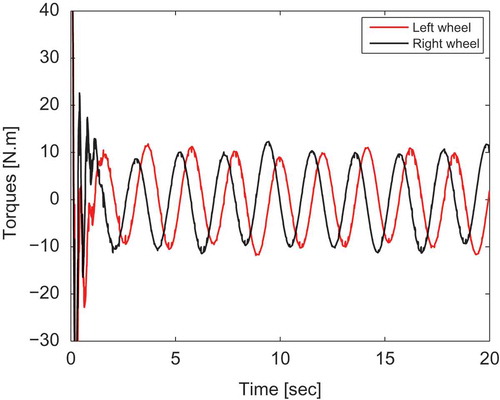
The proposed adaptive sliding mode torque controller ensures good tracking performance in the presence of sinusoidal disturbances, as shown in (a). The tracking errors converge to zero asymptotically (–)). Actual velocity of the robot system converges to the desired velocity generated by the adaptive kinematic controller (). The estimation procedure is successfully performed using the adaptive disturbance estimator, where the actual and estimated disturbances are almost confused (). Indeed, estimated disturbance vector is utilized to enhance the compensation of the unknown disturbances that affect the system, to ensure accurate tracking of the desired trajectory. shows that input torques are similar to the disturbances affected by the robot, in order to compensate for them.
Although mobile robot dynamics are uncertain, the proposed adaptive sliding mode torque controller maintains good tracking ability of the sinusoidal trajectory as shown in . Moreover, it keeps an accurate estimation process of the sinusoidal disturbances, where the estimated disturbances are closed to the actual ones (). In addition, the input torques in the case when dynamics are known () is similar to the one obtained when dynamics are unknown (). This confirms the effectiveness of the proposed controller and its indifference toward dynamic uncertainties.
From –, we can conclude that the proposed controller can successfully track a desired trajectory in the presence of external disturbances and parameter variation.
Figure 3. Tracking performance of the proposed adaptive sliding mode control in the presence of sinusoidal disturbances
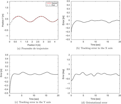
Figure 4. Velocity command and actual velocity in the presence of sinusoidal disturbances
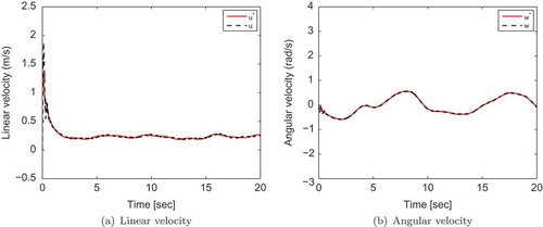
Figure 5. Actual and estimated sinusoidal disturbances
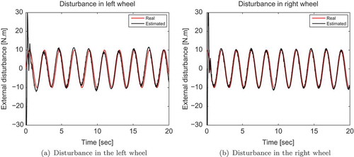
Figure 6. Input torques at the wheels in the presence of sinusoidal disturbances
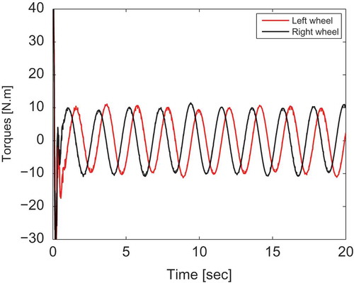
Figure 7. Trajectory tracking of the proposed adaptive sliding mode controller in the presence of sinusoidal disturbances and uncertainties
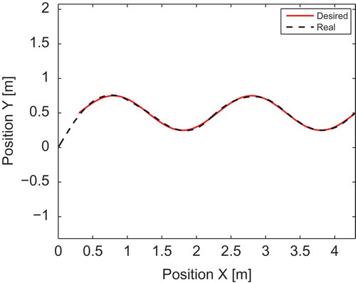
Figure 8. Actual and estimated sinusoidal disturbances
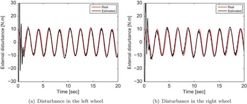
Figure 9. Input torques at the wheels in the presence of sinusoidal disturbances
Conclusions
This article deals with trajectory tracking problem of a nonholonomic mobile robot. A new adaptive sliding mode torque controller is proposed for a mobile robot affected by disturbances and uncertainties. In addition, an estimator term is designed to guarantee compensation of unknown disturbances. Based on Lyapunov method, we have demonstrated that errors converge to zero asymptotically. Finally, the efficiency of the proposed control system is verified by simulation results.
Disclosure statement
No potential conflict of interest was reported by the authors.
References
- Arab, A., and M. M. Fateh. 2015. An uncertainty compensator for robust control of wheeled mobile robots. Advanced Robotics 29 (20):1303–13. doi:10.1080/01691864.2015.1059366.
- Asif, M., M. J. Khan, and N. Cai. 2014. Adaptive sliding mode dynamic controller with integrator in the loop for nonholonomic wheeled mobile robot trajectory tracking. International Journal of Control 87 (5):964–75. doi:10.1080/00207179.2013.862597.
- Chen, C. Y., T. H. S. Li, Y. C. Yeh, and C. C. Chang. 2009. Design and implementation of an adaptive sliding-mode dynamic controller for wheeled mobile robots. Mechatronics 19 (2):156–66. doi:10.1016/j.mechatronics.2008.09.004.
- Dong, W., Y. Xu, and W. Huo. 2000. On stabilization of uncertain dynamic nonholonomic systems. International Journal of Control 73 (4):349–59. doi:10.1080/002071700219704.
- Gao, H., X. Song, L. Ding, K. Xia, N. Li, and Z. Deng. 2014. Adaptive motion control of wheeled mobile robot with unknown slippage. International Journal of Control 87 (8):1513–22. doi:10.1080/00207179.2013.878038.
- Gracia, L., F. Garelli, and A. Sala. 2013. Integrated sliding-mode algorithms in robot tracking applications. Robotics andComputer-IntegratedManufacturing 29 (1):53–62.
- Hoang, N. B., and H. J. Kang. 2016. Neural network-based adaptive tracking control of mobile robots in the presence of wheel slip and external disturbance force. Neurocomputing 188:12–22. doi:10.1016/j.neucom.2015.02.101.
- Huang, D., J. Zhai, W. Ai, and S. Fei. 2016. Disturbance observer-based robust control for trajectory tracking of wheeled mobile robots. Neurocomputing 198:74–79. doi:10.1016/j.neucom.2015.11.099.
- Liu, S., Q. Yu, and H. Zhang. 2009. Real-time trajectory tracking of mobile robots based on sliding mode control using IRBFNNS. Intelligent Automation & Soft Computing 15 (2):167–85. doi:10.1080/10798587.2009.10643023.
- Matveev, A. S., H. Teimoori, and A. V. Savkin. 2011. Navigation of a unicycle-like mobile robot for environmental extremum seeking. Automatica 47 (1):85–91. doi:10.1016/j.automatica.2010.10.003.
- Matveev, A. S., H. Teimoori, and A. V. Savkin. 2012. Method for tracking of environmental level sets by a unicycle-like vehicle. Automatica 48 (9):2252–61. doi:10.1016/j.automatica.2012.06.030.
- Onat, A., and M. Ozkan. 2015. Dynamic adaptive trajectory tracking control of nonholonomic mobile robots using multiple models approach. Advanced Robotics 29 (14):913–28. doi:10.1080/01691864.2015.1014836.
- Pamosoaji, A. K., P. T. Cat, and K. S. Hong. 2014. Sliding-mode and proportional-derivative-type motion control with radial basis function neural network based estimators for wheeled vehicles. International Journal of Systems Science 45 (12):2515–28. doi:10.1080/00207721.2013.772678.
- Singh, M. K., and D. R. Parhi. 2011. Path optimisation of a mobile robot using an artificial neural network controller. International Journal of Systems Science 42 (1):107–20. doi:10.1080/00207720903470155.
- Wang, H., T. Fukao, and N. Adachi. 2002. Adaptive tracking control for nonholonomic systems with unknown parameters. Advanced Robotics 16 (2):175–90. doi:10.1163/156855302760064228.
- Xin, L., Q. Wang, J. She, and Y. Li. 2016. Robust adaptive tracking control of wheeled mobile robot. Robotics and Autonomous Systems 78:36–48. doi:10.1016/j.robot.2016.01.002.
- Yang, J., R. Ma, Y. Zhang, and C. Zhao. 2012. Sliding mode control for trajectory tracking of intelligent vehicle. Physics Procedia 33:1160–67. doi:10.1016/j.phpro.2012.05.191.
- Ye, J. 2015. Tracking control of two-wheel driven mobile robot using compound sine function neural networks. Connection Science 25 (2–3):139–50. doi:10.1080/09540091.2013.851174.
- Yue, M., F. Tang, B. Liu, and B. Yao. 2012. Trajectory-tracking control of a nonholonomic mobile robot: Backstepping kinematics into dynamics with uncertain disturbances. Applied Artificial Intelligence 26 (10):952–66. doi:10.1080/08839514.2012.731347.