
 ?Mathematical formulae have been encoded as MathML and are displayed in this HTML version using MathJax in order to improve their display. Uncheck the box to turn MathJax off. This feature requires Javascript. Click on a formula to zoom.
ABSTRACT
This work details the design, construction, implementation and testing of a standalone robot, based on a convolutional neural network, which receives a voice command, searches and recognizes the target through its camera and moves to the object or person properly recognized. The success rate for the recognition stage has reached 82% in the median for objects tested, 100% for chairs, bottles and people. The processing was performed on a Raspberry Pi 3 B board integrated with an Arduino UNO to control the actuators.
Introduction and Motivation
Robotics is a field that is currently drawing more attention. According to the International Federation of Robotics, up to 1.4 million industrial robots will be installed in factories around the world by 2019, totalizing 2.6 million of industrial robots by the end of the year, surpassing the global record of 2015 by one million (Robotics Citation2016). The applications of this technology grow exponentially and are incorporated in various fields, such as medicine, security, entertainment, transportation and more. Evolution in technology has favored the usage of robots in mundane tasks too, such as domestic robots that help on chores, which seek to improve the overall quality of life and comfort. In summary, robotics permeates the most varied areas of science and has concrete applications nowadays.
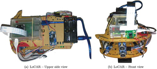
This paper presents the design and implementation of a robot called LoCAR – Low-Cost Autonomous Robot for object detection with voice command (). The device receives a command, analyzes the environment around it trying to find the object and, in success case, move to the target. This chain of actions can be used to look for mundane objects such as keys, cell phones, TV remotes, wallets or even be used in rescue and recovery efforts, identifying a person in rubbles, being possible to create an object recognizing solution for a large number of situations that costs less than U$ 100 (values of December/2018).
Figure 1. LoCAR – Low-Cost Autonomous Robot views.
This paper is organized as follows: The Related Works section presents some theoretical foundations. The Materials and Methods section describes the physical components of the robot, how they interact, the logical components and their implementations. In the Object Detection and Highlighting section is detailed how the robot uses the convolutional neural network to find the object and centers in its direction. The following section is Experiments and Results where tests and results obtained are reported, and finally, the Conclusion and Perspectives section concludes the text and raises possibilities for further research.
Related Works
Among the traditional object recognition methods based on image processing algorithms, there are texture-based segmentation (Lucieer, Stein, and Fisher Citation2005), contour-based (De Winter and Wagemans Citation2004) or color region (Danneels and Sampat Citation2002); however, with the popularization of Artificial Neural Networks, multiple feature recognition systems based on neural models are currently being researched, developed and tested (Szegedy, Toshev, and Erhan Citation2013). Nowadays, a considerable amount of those systems is incorporated into industrial robots and the most known example is embedded systems for self-driving vehicles (Sun et al. Citation2015).
A paper written by (Tronco, Júnior, and Porto Citation2003) describes an industrial robot that identifies parts using as input noisy images and images that were generated after some type of image transformation on the original image. After multiple neural network configurations and architectures, an accuracy rate greater than 90% was achieved.
A prototype described by the authors (Debroy et al. Citation2016) aims to create advanced models based on automated systems in which the robot is capable of detecting and tracking a moving object. The authors describe the development of an Android app that uses OpenCV for the implementation of tracking and object detection in real time, where the Android device pairs itself with the robot via bluetooth and acts as their “eyes and brains” and the robot itself acts as the “body.” Another similar work was described by (Astua et al. Citation2014), using cameras and Microsoft Kinect®, they use border detecting algorithms and feature extraction making the robot can detect, classify and trace a route to a given object.
There are multiple uses for neural networks on image pre-processing that involve reconstruction, restoration and enhancement techniques (Ma et al. Citation2018) (Sun et al. Citation2015) (C. Y. Lin and S. H. Lin Citation2005). Another example is image feature extraction which can generate attributes based on filters (Fukushima and Miyake Citation1982) (Mao and Jain Citation1995). In the same context, the robot described in this paper employs a combination of image processing techniques and convolutional neural networks. The model implemented in the robot belongs to the MobileNets class (Howard et al. Citation2017), proposed by a Google research team for applications involving computer vision on mobile devices. The development combines the architecture of MobileNets with the SSD – Single Shot MultiBox Detector (Liu et al. Citation2016), which is characterized by the ability to reproduce bounding boxes bordering the identified objects and, consequently, highlighting them in the image. The MobileNets with SSD approach was also used in (Liang et al. Citation2018) to identify different foods in the same meal through a single cell phone photo.
This paper considers all related work and employs a neural network optimized for low-memory embedded systems that include voice command system, object recognition, displacement to it and beeping as location confirmation.
Materials and Methods
This section details the used hardware, their integrations, logical units and some explanations about the algorithm implementation. It is worth to evidence that one of the objectives of this study is to offer a low-cost (US$ 100.00) device to find objects, and more general purpose, so, this imposes some constraints on technologies, controllers, sensor and other components. Nevertheless, the Results section is interesting given the conditions mentioned.
Hardware
This subsection lists the components, their integrations and the basic operation of some sensors used in the assembly of LoCAR – :
Arduino UnoFootnote1
Raspberry Pi 3 BFootnote2
PiCam 5MP
2 step motors 28BYJ-48
2 wheels
1 ball metal-bearing wheel
2 infrared sensors
1 Buzzer
2 ULN2003 Drivers
Raspberry case with 5 V cooler
Step-down voltage regulator
4 batteries model 18650
1 ultrasonic sensor
2 double 18650 battery holder
Car robot chassis
The microcomputer Raspberry Pi 3 has embedded Wi-Fi and uses the operating system Raspbian to run the main program written in the C++ language, the PiCam module, connected on the Raspberry Pi’s CSI camera port, is used for capturing the neural network input images for object recognition and, also, the board has been equipped with a 5 v 20 mm cooler and aluminum heatsink to assist in heat dissipation due to the considerable amount of processing.
The Arduino microcontroller is responsible for controlling the step motors via ULN2003 drivers, the buzzer and interfacing the obstacle avoidance sensors. Initially, DC 6 V motors were used and the results were not good because the variations in the rotation frequency made it difficult to travel in a straight line. Among the attempts to correct its trajectory, a tracking algorithm was used with video capture instead of images by PiCam, but the capture and encoding processing made this method return less efficient results due to hardware limitations. Raspberry Pi’s native configuration is insufficient to load the neural network into memory and capture video at the same time. Another option used was to load the neural network only when the classification was necessary, this alternative was also disregarded due to the delay of approximately 13 seconds for each processing and for this reason, the present work contemplates the use of stepper motors whose frequency of rotation is the same between the two motors, thus mitigating the straight line displacement problem.
The Infrared (IR) sensor uses two LEDs (sender and receiver) on each module to detect obstacles. When an object is found, the IR signal beam by the sender is reflected and detected by the receiver. Due to the dependence of signal reflection, it is harder to detect translucent or very dark objects and this sensor is not recommended to environments with incident sunlight because of the intensity of IR light from the sun, which compromises receiver correct identification. Similarly, the ultrasonic sensor also works based on signal emission and reception (sonorous), beam an ultrasonic pulse, waits for its return via reverberation and, using the time interval between output and input, is able to calculate the distance of the reflecting object, been effective on translucent or very dark objects. On the other hand, it has poor performance if the object is not perpendicular to the sensor because the signal can be reflected in another direction which makes reception difficult or on objects with no orthonormal faces, i.e. cylindrical or rounded objects.
The robot is powered by two sources: first, two batteries model 18650 Li-ion battery with 2400 mAh 3.7 V feed Raspberry and Arduino board, and the second, two other batteries of the same model power the stepper motors.
System Components
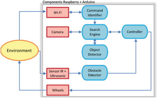
The system main components can be seen in the diagram of , which the red rectangles represent physical components and the blue ellipses the logical units, as detailed below:
The Command Identifier is the logical component that captures data from the Wi-Fi network, in this case a string (generated by the audio/voice recognition system) and attempts to identify a valid command to the robot. If so, triggers the Search Engine.
The Search Engine controls and administers the other components for the object search step. This component triggers the Camera for image capture, sends it to the Object Detector, analyzes its output and send commands for moving or beeping to the Controller.
The object detector is where the neural network is implemented and its purpose is to detect the presence of the target object and return the object’s contour coordinates if found.
The Controller was implemented using the Arduino IDE, runs on an Atmega328 microcontroller and receives low level commands for motor movement and sound emission through the serial port – buzzer. It is also responsible for controlling the robot’s stop when blocked by an object.
Obstacle Detector, also implemented in Arduino, has the function of monitor the infrared and ultrasonic sensors, returning to the Controller the existence of any object in front of the robot.
Figure 2. System components.
Implementation
An Android app () connects to Raspberry over Wi-Fi and sent to the board the voice commands that are transformed into text using Android’s native methods (Google Citation2018). The main program in Raspberry receives the string, validates it through the Command Identifier, i.e., verify if the command is included into the robot’s preprogrammed dictionary (for example, “Find a chair”) and, being a recognized command, the device starts scanning the environment with the purpose of finding an object that has the target characteristics.
Figure 3. Screenshot of voice command capture application.

The search is performed by capturing multiple images, detections and recognition by the neural network as follows:
The image is captured, if the object is found then robot faces the object and moves in a straight line until it reaches the object and then beeps;
If the target object was not found, the robot rotates to the left by approximately 45 degrees and resumes the process;
If after 8 more tries (8 x 45º = 360º) the object was not found in the environment, the search ends with a fail beep alert.
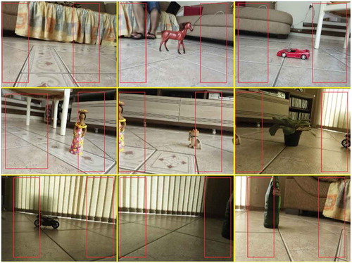
It is important to emphasize that performing 8 turns of 45 degrees contemplates the 360 degrees safely with no blind spot because RaspCam’s Field of View is 62.2 degrees. shows the 360-degree sequencing images. Yellow lines help identify each of the 9 images and, the manually added, red rectangles help to identify “360-degree points.”
Figure 4. Sequence of images captured in 360 degrees rotation.
The detection step compares the captured object with the target object. If it is a match, the robot is centered based on the image coordinates that allow to identify the direction and translation value from the center point of the outline on the abscissa’s axis relative to the center of the image. The robot will move toward the object until one of the sensors detects any obstruction and stopping at approximately 5 cm from it. After 1.5 seconds a new reading is taken and, if the object remains obstructing its path, the robot considers it has hit the target emitting the success sound (represented by 3 beeps). In case an obstacle is removed within 1.5 seconds, the robot resumes movement, preventing a small block in its path from stopping before reaching its target and mistakenly returns a found object.
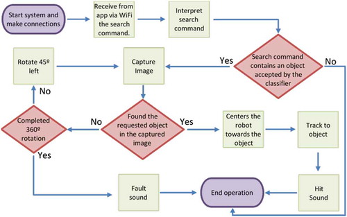
The robot’s motion commands and sounds are transmitted to Arduino through the Raspberry serial port. The microcontroller constantly monitors this port and whenever a new command is received it is analyzed but is unnoticeable in execution. presents a flowchart summarizing the basic operation process.
Figure 5. Flowchart of basic robot operation.
Object Detection and Highlighting
In the last years, the detection and recognition of objects have presented several advances due to the development and application of deep neural networks. This paper is based on the use of convolutional networks provided by (Howard et al. Citation2017), whose combination with classical computer vision techniques represents state of the art and has shown promising results.
The task of searching and detecting objects requires the use of deeper neural network architectures or with a high number of parameters, thus implying high processing time and temperature increase. In this sense, the detection system developed in LoCAR uses a convolutional neural network – based on MobileNet (Howard et al. Citation2017), which presents an architecture for computer vision applications optimized for devices with hardware limitations. As described by the authors in (Liang et al. Citation2018), MobileNets “use the idea of deep separable convolutions,” i.e., the decomposition of the “standard convolution” in two convolutions: one in depth and one in points. This strategy “can effectively reduce the computational cost and reduce the size of the model,” allowing to use it with memory and processor limitations such as Raspberry Pi 3 used in this project.
The implemented neural network has good speed, requires little memory and, as experiments have shown, the accuracy obtained with the model is adequate for the location of objects such as people, chairs, tables, bottles, TVs and more, for a total of 20 objects available in set.
Originally the model was trained using the COCO – Common Objects in Context data set (T. Y. Lin et al. Citation2014) and in this work it was retrained with the PASCAL Visual Object Classes (VOC) set (Everingham et al. Citation2010) using the fine-tuning technique, evidencing that it is possible to change the data set by keeping the model, just retraining it and thus making the application more versatile because the set of objects that the robot recognizes can be changed depending on the context in which it is inserted.
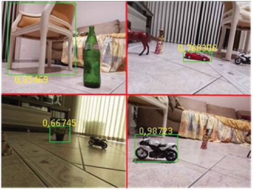
To suit the MobileNet input standard (Howard et al. Citation2017) all frames are resized to dimensions 300 × 300 pixels, converted to BLOB file in sequence and, after network processing, a result set is generated containing the class identifications and their probabilities of the recognized objects in the scene. presents some images highlighting the bounding boxes of objects and their respective consideration percentages returned by the neural network.
Figure 6. Detection step using various types of objects.
In addition, we get the coordinates of the pixels representing the vertices of the rectangles that contain each identified target in the image (coefXNeural and coefYNeural), allowing us to use the SSD for highlighting them through bounding boxes on the original picture regardless of the dimensions, as shown in . The calculations for these coordinates are given in Equationequations 1(1)
(1) and Equation2
(2)
(2) :
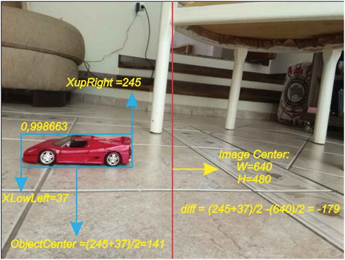
To obtain the coordinates contour boxes’ vertices are employed in the lower left and upper right. This information makes it possible to calculate how far from the center of the image is the center of the boundary box of the identified object. The images captured in this experiment have dimensions 640 × 480 pixels, so:
imageHorizontalDimension = 640
imageVerticalDimension = 480
The difference between the center point of the image and the center of outline is defined in Equationequation 3(3)
(3) :
In Equationequation (3)(3)
(3) , if (diff)
0 means that the center of the object is to the right of the frame and if (diff)
0 then it is to the left.
In , the variables related to Equationequation 3(3)
(3) calculations are exemplified. To perform the centering in the horizontal axis, the variables of interest are lower-left-x and the upper-right-x coordinates of the boundary box, provided by the neural network and highlighted in . The value of (diff), in this case, is −179 which means that the object is shifted to the left of LoCAR in the scene.
Figure 7. Original image and composition of image centering variables.
In sequence, the translation to align LoCAR to the object takes place, which is given in Equationequation 4(4)
(4) :
The is the correlation between the image pixels and the angle captured by the camera. The RaspCam v2 field of view angle is 62.2 degrees and the images captured by the camera are originally 640 × 480 pixels, so it is necessary to calculate the amount of degrees each pixel represents in the image and thus to center the robot toward the identified object. The
is given in Equationequation 5
(5)
(5) :
Considering imageHorizontalDimension is 640 pixels, each pixel of the images represents about 0.0971º, and with this value, it is possible to find the value in degrees which the robot needs to rotate to center the image to its axis. To do this, you must know the accuracy of the robot motors and according to the 28BYJ-48 engine manufacturer (Kiatronics Citation2017), the “stride angle” of this model is 5,625º/64 0,08º; therefore, the accuracy of each “step” of the engine is close to the amount needed for one-pixel correction, allowing the robot to center efficiently and accurately. For instance, considering Equationequation 4
(4)
(4) and replacing the values given in , resulting:
angleT = −179*0.0971
angleT = −17,308 −17
This value means that the object is about 17 pixels to the left of the center, requiring 217 engine “steps” to center the robot toward the object, as exemplified in Equationequation 6(6)
(6) :
Experiments and Results
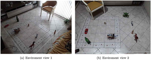
Most of the tests performed in a domestic environment are represented in . The main factor for selecting this environment was the control over the incidence of sunlight. Some objects were intentionally added as noise to the captured images (ceramic dog, doll and a miniature horse).
Figure 8. Main test environment.
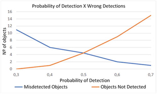
To initialize the experiments, consideration threshold tests for the true recognition of a possible object were performed, seeking the best identification rate and minimize the false positives. illustrates that increasing the probability needed to consider an object decreases the number of inconsistencies and inaccurate detections (exemplified in the range from 30% to 50%); however, as the threshold is increased, even objects that should be detected, are not, as an example using 80%.
Figure 9. Consideration threshold variations using chairs.
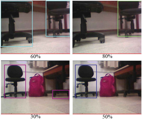
Analyzing , it can be seen that the intersection of the incorrect object detection curves and the non-detection curve intersect very close to the 50% probability, and this is where the smallest maximum (Osborne and Rubinstein Citation1994) (Russell and Norvig Citation2016) error is, i.e. the best consideration threshold.
Figure 10. Graph: Number of misdiagnoses by probability.
More than 60 tests were performed to evaluate how reliably are the object detecting and the correct displacement to the identified ones. The results in show the experiments to chair, bottle, motorcycle, car, plant and people. The distance from the robot to the objects ranged from 70 cm to 2.5 m.
Table 1. Results of Experiments.
As can be seen in , except for car object detection, the lowest rate achieved was 67%. The lower hit rate presented in the car detection was possibly influenced by the model used in the tests (sports car miniature). It is also worth highlighting the positive results in the detection of bottle, chairs and people all presenting 100% hits. After detection, the robot centers the object and moves straight to the target in all the tests performed. The average detection rate was 82% with 100% of right displacements, which is considered satisfactory rates showing that the robot although presenting difficulties for some objects (miniature vehicle), fulfills the initial objective.
Conclusion and Perspectives
This work aimed to design, build and implement a robot to identify objects with voice commands and with a maximum value of US$ 100.00. Despite having a simple structure and cheap hardware it can achieve the proposed objectives satisfactorily. The implemented neural network is fast and efficient for identifying objects around the robot, with an average hit rate of 82% and individual hit ranging from 50% in the worst case (sports car) to 100% in the best case (chair, bottle, people). The robot’s centralization toward the identified objects and the displacement showed 100% accuracy in the tests.
Despite the positive results, there are points of attention about the project such as the robot’s structure is still limited and has difficulty moving on uneven surfaces, the search for the object is performed only around the robot and the infrared sensor is very sensitive to sunlight. Considering these limitations, for the future, some suggestions for improvement in this work are:
Consider returning to the starting point;
The exhaustive (or expanded) search in the environment and not just around;
Increase the number of cameras and processing capacity;
Employ a different classifier algorithm, such as SVM, Random Forest and Deep Learning;
Test the same environment by changing only the neural network training set.
Also, it is important to note that this is an initial and general-purpose project; therefore, it is expected that it can be employed in various situations from environment monitoring, unhealthy rescue to educational or entertainment. Finally, as evidenced earlier, robotics permeates the most varied areas and consolidates itself as horizontal before the most diverse segments of science.
Acknowledgments
Credit to Abner F. Bertelline, Alesia N. B. Melo, Felipe J. L. Rita and Leonardo M. Tozato for developing the initial version of the LoCAR robot.
Notes
1. https://www.arduino.cc/
2. https://www.raspberrypi.org/
References
- Astua, C., R. Barber, J. Crespo, and A. Jardon. 2014. Object detection techniques applied on mobile robot semantic navigation. In Sensors, 6734–57. doi:10.3390/s140406734.
- Danneels, G. D., and K. R. Sampat. Color region based recognition of unidentified objects. US Patent 6,393,147. May 2002.
- De Winter, J., and J. Wagemans. 2004. Contour-based object identification and segmentation: Stimuli, norms and data, and software tools. Behavior Research Methods, Instruments, & Computers 36 (4):604–24. doi:10.3758/BF03206541.
- Debroy, S., N. Kumari, P. Singh, S. Kude, and P. Sheikh. International Journal of Computer Science and Mobile Computing Object Detection and Tracking Robot using Android, Arduino and Open CV. Tech. rep. 2016, pp. 187–91. www.ijcsmc.com.
- Everingham, M., L. Van Gool, C. K. I. Williams, J. Winn, and A. Zisserman. 2010. The pascal visual object classes (VOC) challenge. International Journal of Computer Vision 88 (2):303–38. doi:10.1007/s11263-009-0275-4.
- Fukushima, K., and S. Miyake. 1982. Neocognitron: A self-organizing neural network model for a mechanism of visual pattern recognition. In Competition and cooperation in neural nets, IEEE Transactions on Systems, Man, and Cybernetics. SMC-13 (3): 826–834. doi:10.1109/TSMC.1983.6313076.
- Google. TextToSpeech Android Developers. 2018. https://developer.android.com/reference/android/speech/tts/TextToSpeech (visited on 10/ 30/2019)
- Howard, A. G., M. Zhu, B. Chen, D. Kalenichenko, W. Wang, T. Weyand, M. Andreetto, and H. Adam. 2017. Mobilenets: Efficient convolutional neural networks for mobile vision applications. In arXiv preprint arXiv:1704.04861.
- Kiatronics. 28BYJ-48 Datasheet. 2017. https://datasheetspdf.com/pdf/1006817/Kiatronics/28BYJ-48/1 (visited on 10/ 30/2019)
- Liang, H., Y. Gao, Y. Sun, and X. Sun. 2018. CEP: Calories estimation from food photos. International Journal of Computers and Applications 1–9. doi:10.1080/1206212X.2018.1486558.
- Lin, C. Y., and S. H. Lin. 2005. Artificial neural network based hole image interpretation techniques for integrated topology and shape optimization. Computer Methods in Applied Mechanics and Engineering 194 (36–38):3817–37. doi:10.1016/j.cma.2004.09.005.
- Lin, T. Y., M. Maire, S. Belongie, J. Hays, P. Perona, D. Ramanan, P. Dollár, and C. L. Zitnick. “Microsoft coco: Common objects in context.” In: European conference on computer vision. Zurich, Switzerland: Springer. 2014, pp.740–55.
- Liu, W., D. Anguelov, D. Erhan, C. Szegedy, S. Reed, C.-Y. Fu, and A. C. Berg. 2016. Ssd: Single shot multibox detector. In European conference on computer vision, 21–37. Springer, Cham. doi: 10.1007/978-3-319-46448-0_2
- Lucieer, A., A. Stein, and P. Fisher. 2005. Multivariate texture-based segmentation of remotely sensed imagery for extraction of objects and their uncertainty. International Journal of Remote Sensing 26 (14):2917–36. doi:10.1080/01431160500057723.
- Ma, K., F. Huan, T. Liu, Z. Wang, and D. Tao. 2018. Deep blur mapping: Exploiting high-level semantics by deep neural networks. IEEE Transactions on Image Processing 27 (10):5155–66. doi:10.1109/TIP.2018.2847421.
- Mao, J., and A. K. Jain. 1995. Artificial neural networks for feature extraction and multivariate data projection. IEEE Transactions on Neural Networks 6 (2):296–317. doi:10.1109/72.363467.
- Osborne, M. J., and A. Rubinstein. A course in game theory. MIT press, 1994. Robotics, International Federation of. World Robotics Report 2016. 2016. https://ifr.org/ifr-press-releases/news/world-robotics-report-2016 (visited on 10/ 30/2019)
- Russell, S. J., and P. Norvig. 2016. Artificial intelligence: A modern approach. Boston, MA, USA: Pearson Education Limited.
- Sun, J., W. Cao, X. Zongben, and J. Ponce. “Learning a convolutional neural network for non-uniform motion blur removal.” In: Proceedings of the IEEE Conference on Computer Vision and Pattern Recognition, Boston, MA, USA. 2015, pp. 769–77.
- Szegedy, C., A. Toshev, and D. Erhan. 2013. Deep neural networks for object detection. In Advances in neural information processing systems, 2553–61.
- Tronco, M. L., A. M. Júnior, and A. J. V. Porto. 2003. Sistema de Reconhecimento de Imagens para Robô de Montagem: Implementação e Estudo de Caso. In VI Simpósio Brasileiro de Automac¸˜ao Inteligente. Bauru, setembro de. Universidade Estadual Paulista.