
 ?Mathematical formulae have been encoded as MathML and are displayed in this HTML version using MathJax in order to improve their display. Uncheck the box to turn MathJax off. This feature requires Javascript. Click on a formula to zoom.
ABSTRACT
In order to improve the practical effect of clothing design, this paper applies the relevant theories of behavioral psychology to the design of fashion clothing, and improves the algorithm through the intelligent psychological identification algorithm to construct a quantitative identification system of behavioral psychology to help designers design more comprehensively. At the system level, the overall structure of the entire behavioral psychological ECG signal acquisition system is planned, and the Multisim software is used to simulate and verify whether each module of the front-end processing circuit achieves the expected effect according to the calculated parameters. In addition, on the basis of verifying the reliability of quantitative identification of behavioral psychology, the construction of intelligent clothing design system is carried out. Finally, this paper combines the simulation test and evaluation test to verify the effect of the system in this paper. Through the experimental research, it is verified that the clothing design system based on behavioral psychology proposed in this paper can effectively improve the clothing design effect and user experience.
Introduction
Related Work
For individuals, people grow up in society, and clothing also plays a certain role in the process of transforming from natural people to social people (Abdullajonovna, Kizi, and Khayitovna Citation2021). The literature (Jin and Shin Citation2021) mentioned that “design is actually a communication process, and designers must have a deep understanding of their communication objects.” To a large extent, design psychology has the significance of guiding and restricting clothing design, because the original intention and final purpose of clothing are for people’s wearing and consumption. Moreover, design psychology, as the theoretical basis of the current human-oriented clothing design, can better solve many problems faced by people, such as why to design, how to design, and how to design better (Starkey et al. Citation2021). Without the support of design psychology, the so-called clothing design for people itself becomes an empty talk. As people’s requirements for the clothing design market are getting higher and higher, the psychological control of consumers has also become an important factor in design. People need both material and spiritual satisfaction, so if designers want to move forward, they need the theoretical support of design psychology (Jasiuk et al. Citation2018).
Compared with other characteristics, the color of clothing is the first to break into people’s eyes, and it is also the first to stimulate the retina. When people walk into a clothing store, the first thing they notice is the color of the clothing more than any other factor. Moreover, disliked colors will directly affect people’s purchasing sentiment (Mackey et al. Citation2017). The World Fashion Color Association is based on people’s consumption psychology, and uses various scientific means every year to predict and release popular colors so as to affect the popularity and influence people’s consumption (Black, Freeman, and Rawlings Citation2018). Because people have lived in a world of color for a long time and accumulated a lot of visual experience, once the sight of the eye collides with the visual experience that has been formed in the brain before, people’s emotions and psychology will have certain changes (Zhao Citation2018).
Fashion clothes serve more mainstream groups, and color is more closely related to the psychology and behavior of most groups, and is more likely to cause group associations, resonance and other psychological effects (Gill and Parker Citation2017). Behavioral psychology in fashion design studies the intersection of psychology and art design. At the same time, its research subject should not only study the behavioral psychological relationship between consumers (users) and clothing, Clothing market research can assist a business in identifying new target markets, understanding current customers feel about their brand, gaining insights into fashion spending, and examining marketing campaigns can affect purchasing behavior. All textile and clothing products are developed and created using design principles. But also, the behavioral psychological relationship between designers and clothing (Park et al. Citation2019). As one of the important design elements in clothing design, color trends are also influenced by color psychology and behavioral psychology. Moreover, color is not only a visual element in clothing design, but also affects others’ judgments on factors such as the wearer’s personality, mood, and social status. At the same time, individual differences reflect the choice of color after being affected by different environments, thus affecting the development of color trends (Miell, Gill, and Vazquez Citation2018). Color trends can be divided into: predicted colors in the color trend forecast report, and popular colors with high popularity obtained through data statistics in social activities. By analyzing the influence of color trends on people’s psychological associations and behavioral activities from these two aspects, the research on color trends in fashion design is more complete (Kim and Ha-Brookshire Citation2019). Behavioral psychology studies the relationship between the psychological and behavioral responses of individuals after receiving different color information, and its role in fashion design (Milošević et al. Citation2018).
Objectives
Based on the theory of behavioral psychology, this paper studies the color trend of fashionable clothing, and analyzes the interaction between the color trend in each link of clothing design and other design elements. Moreover, this paper applies the relevant theories of behavioral psychology to the color design of fashion clothing, which can help designers to design more comprehensively. At the same time, this paper discusses the psychological effect of color information on people with the social environment as the key influencing factor. Finally, this paper combines behavioral psychology to conduct research on clothing design from the perspective of big data, so as to improve the effect of clothing design and improve the user’s dressing experience. To succeed in the fashion industry, clothing designers also require a great portfolio, professional connections, and work experience. While the influence of psychological, social, economic element, cultural, political, environmental consideration and physiological elements on clothing trends
Methodology
The main research method of this paper is to conduct quantitative tests of behavioral psychology through ECG signals.
Hardware Module Design
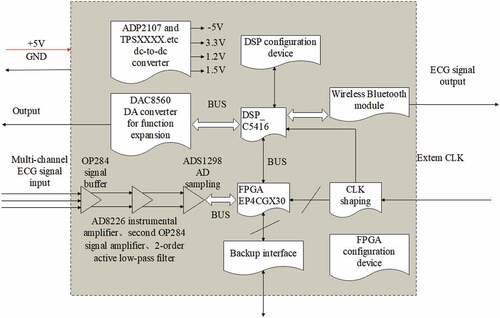
Behavioral psychological ECG signal amplitude is generally between 0.05 ~ 5 mV, frequency is 0.05 Hz ~100 Hz. Therefore, the behavioral psychological ECG signal must first be amplified and filtered, and then converted into a digital signal, and the behavioral psychological ECG signal can be processed and analyzed by software. ECG is used to analyze a person’s psychological condition. The frequency of ECG signals spans from 0.5 Hz to 100 Hz, and artifacts are a significant factor in their processing. Typically, the letters P, Q, R, S, and T are used to represent the ECG signal. P and T stand in for low-frequency components, whereas QRS complex stands in for high-frequency components. Similarly, the basic heuristic fusion and fuzzy comprehensive evaluation of the SQIs serve as the foundation for the suggested ECG quality assessment technique. The behavioral psychological ECG signals of the input channel of the ECG system come from ten leads in six places: the right hand, the left hand, the right leg, the left leg and the chest. is a block diagram of the hardware principle of the behavioral psychological ECG signal acquisition system. The following sections of this chapter will introduce each module of this block diagram in detail.
Figure 1. Block diagram of the behavioral psychological ECG signal acquisition system.
Amplifier Pre-Stage Analysis
During ECG acquisition, the preamplifier is related to the common mode rejection ratio and is the core of the amplifier, so the design of the preamplifier is an important part. The ECG signal is first amplified by the ECG preamplifier. In order to prevent micro shock, the isolation circuit lowers leakage current to and from the patient through the electrode/lead wire connection. Accurate electrode placement is also crucial part in obtaining an accurate ECG. Whereas improperly positioned electrodes may cause erroneous interpretation, incorrect condition diagnoses, and poor administration of patient treatment. According to the amplitude characteristics of the behavioral psychological ECG signal, three indicators need to be proposed, An ECG can be used to detect either an exceptionally fast or slow heart beat. The P wave, which indicates depolarizing atria, the QRS complex, which indicates the depolarization of the ventricles, and the T wave, which depicts depolarizing ventricles, is the three primary indicators of an ECG and the actual amplifier pre-circuit is designed in combination with the principle under the premise of satisfying the indicators.
The digitized signals of voice, audio, video, temperature, pressure, or position are taken by digital signal processors (DSP) and computationally manipulated. Mathematical operations like “add,” “subtract,” “multiply,” and “division” can be completed fast with a DSP. The ECG data is preprocessed using the DSP filter to remove noise from the ECG signal. Many filtering techniques, including Low pass, High bass, and Bandpass filters, are available depending on the noise components of the ECG signal.
The characteristics of the behavioral psychological ECG signal source are high internal resistance and small amplitude, which requires the input impedance of the amplifier to be high enough. If the input impedance is not high enough compared to the source impedance, it will cause the amplitude of the signal component entering the differential amplifier to decrease. At the same time, under the condition of large input impedance, the stability of the amplification factor will be reduced due to the error of the impedance in front of the amplifier input. The customizable logic block (CLB) matrix at the center of Field Programmable Gate Arrays (FPGAs), a semiconductor device, is coupled by programmable interconnects. After production, FPGAs can be reprogrammed to meet specific application or feature needs. While developing application-specific integrated circuits or processor prototypes, FPGAs are especially helpful.
RF noise is carried away to the earth and not released as radiation according to proper grounding. The simplest methods for preventing power frequency interference in electrical circuits are shielding, filtering, and grounding. In order to suppress the power frequency interference, a differential amplifier must be used. The differential amplifier’s function is to boost the cardiac signal’s amplitude to a point where it may be digitally encoded. Although, differential amplifiers are mostly used to reduce noise. The resistance of the electrode system is unbalanced, which reduces the actual common-mode rejection capability of the amplifier. When taking psychological ECG signals through two different channels, the equivalent source impedances and
are not exactly the same, and the physical resistances of the two electrodes themselves are not exactly the same, which makes the source impedances
and
very complicated, and the unbalance is absolute. This converts the common mode interference into differential mode interference, Signals or noise that flow in a pair of lines in the same direction are referred to as the common mode. Signals or noise that travel along a pair of lines in the opposite directions are said to be in the differential (normal) mode. External disturbances (like ESD) can couple onto a differential signal as differential noise when common mode to differential mode (CM-to-DM) conversion occurs, causing the interference to be amplified and output. For this conversion, the high common-mode rejection ratio of the amplifier itself cannot do anything, but the input impedance of the amplifier can be increased to reduce this conversion. When a differential signal needs to be amplified in the presence of a potentially substantial common-mode input, such as significant electromagnetic interference, a high CMRR is necessary. But, using the bootstrapping technique, we may connect shunting capacitors across each circuit winding in order to achieve resonance at any desired RF frequency, which lowers the conversion. In ,
is the common-mode interference signal, and the voltage at two points
is:
Figure 2. Amplifier input loop.
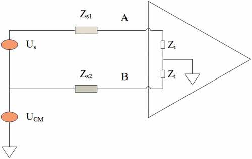
Common mode is converted to differential mode, and the voltage is:
In general, , so
From the formula (2), it can be known that trying to further improve the input impedance of the ECG preamplifier, or reducing the value of can reduce the converted differential mode voltage value. A high CMRR is required when a differential signal must be amplified in the presence of a possibly large common-mode input, such as strong electromagnetic interference (EMI). An example is audio transmission over balanced line in sound reinforcement or recording.
③Low noise and low drift
The behavioral psychological ECG signal is a low-frequency signal with a small amplitude, so the preamplifier is required to have low noise and low drift. Before the electronic pulses enter a line leading to an amplifier, the preamplifier amplifies them by improving the signal-to-noise ratios. Moreover, a pulse-shaping circuit may linearly amplify and shape the output pulses of the preamplifier. The current-sensitive preamplifier, the parasitic-capacitance preamplifier, and the charge-sensitive preamplifier are the three primary types of preamplifiers that are accessible. This determines the quality of the obtained behavioral psychological ECG signal. The DC amplifier can amplify the behavioral ECG signal with very small frequency, but the DC amplifier has a drift phenomenon, which limits the input range. Therefore, through analysis and research, the differential circuit is the best input form, and choosing symmetrical components can effectively suppress the zero drift. Circuits with differential inputs take the voltage difference between two different input signals. A single-ended input is less able to withstand electromagnetic interference (EMI) than a differential input. Moreover, they can present balanced input impedance and reject common-mode voltage better than single input circuit and the majority of the time, symmetrical components are used for analyzing three-phase electrical power systems. By breaking down a three-phase unbalanced system into two sets of balanced phasors and a set of single-phase phasors, or symmetrical components, it is possible to optimize fault analysis.
Analysis of the Disadvantages of the Differential Amplifier Circuit with Single Operational Amplifier
To meet the above high indicators, first of all, it is thought that the pre-stage of the amplifier is composed of a single integrated operational amplifier. The following first analyzes the shortcomings of the conventional single-integrated operational amplifier differential amplifier circuit. Common-mode noise is reduced by using differential amplifiers. One of an op-electrical amp’s characteristics is called the common-mode rejection ratio (CMRR). Increased signal swing, a higher slew rate, and the usage of differential transmission lines all contribute to the benefits. Better impedance matching, decreased sensitivity to generated or coupled noise, and decreased EMI production are all benefits of differential circuits. Whereas, wide bandwidth, low offset voltages and currents, low output impedance, high differential voltage gain, low common mode gain, high CMRR (common mode rejection ratio), high input impedance, and low common mode rejection ratio are the features of differential amplifiers.
shows the differential amplifier circuit, and
are two input signals,
is the common mode voltage, and
is the differential mode signal. Among them,
Figure 3. Differential amplifier circuit.
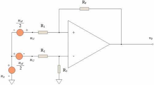
Therefore,
The relationship between the output voltage and the input voltage is obtained from the virtual short and virtual break of the ideal op amp.
Since the currents in and
are equal,
We obtain:
Among them, is the common mode output and
is the differential mode output. The maximum allowed noise or common mode signal loudness and when in operation, it rejects the common mode signal are the limitations of differential mode output. The outer loop resistance determines the values of
and
. If we choose to make the outer loop resistance meet:
The common mode output is 0 and the common mode input
is completely rejected.
It is necessary to eliminate bias current and temperature drift, otherwise it will produce differential mode output, so it should meet:
To meet the two requirements of formula (8) and formula (9), the matching condition can be obtained as:
When formula (10) is satisfied, there is no common mode output. From formula (7), the closed-loop differential mode gain under ideal conditions can be obtained as:
Because of the common-mode gain is , the amplifier is
.
The above is ideal. In fact, it is impossible to absolutely satisfy . In the precise choice of resistance,
can be small, but it can never be zero. CMRR is the ratio of the common-mode gain to differential-mode gain. The capacity of the op-amp to reduce noise in audio, video, and communication devices is ultimately determined by the existence of common-mode signals at the op-amp inputs. Therefore, the CMRR of the amplifier cannot reach
. On the other hand, the limited self-common-mode rejection ratio of the amplifier will affect the overall common-mode rejection capability. A differential amplifier’s common mode rejection ratio is a metric used to measure the device’s capacity to reject common-mode signals. In audio, video, and communication designs, it reveals the presence of common-mode signals at the op-amp inputs, which ultimately affects the op-capacity amp’s to decrease noise. The common mode rejection ratio of the outer loop is
, the common mode rejection ratio of the device itself is
, and the overall common mode rejection ratio CMRR will be taken from
and
together.
First, we analyze the outer loop, and the common mode gain of the amplifier is:
The matching errors of each resistor are:
After substituting various formulas into formula (12), we obtain:
When the error is much smaller than 1, the above formula can be approximated as:
We set the errors to be equal, that is, , and obtain:
The common mode rejection ratio of the external circuit is
Formula (17) shows that is affected by the resistor matching error
and the closed-loop differential mode gain
. To enhance the common mode rejection capability of the amplifier, it is necessary to reduce the resistance matching error and increase the closed-loop differential mode gain. We can increase differential voltage gain or decrease common mode voltage gain to increase or decrease the CMRR, which is the ratio of differential voltage gain to common mode voltage gain. Emitter resistance RE should be raised to increase CMRR. The CMRR’s value is frequently influenced by signal frequency.
First, we derive the common-mode output voltage resulting from being not high enough. According to the definition of the common mode rejection ratio,
is the amplifier open-loop differential mode gain
divided by the common mode gain
, that is:
The common mode gain is:
When is referred to the input, the common-mode error voltage
is:
From formula (18), formula (19), formula (20), we obtain:
It can be seen that the common mode voltage is converted into a differential mode voltage, forming a common mode interference voltage. The of the op amp itself is responsible for this conversion. Therefore, since
is not infinite, the common mode output
is generated, and the equivalent effect brought by referring to the input end is a differential mode voltage
, which is amplified by
times.
In this way, due to the limited of the outer loop, the resulting common mode error voltage is:
Among them, is represented by formula (12), and
is represented by formula (11). The total mode gain of the amplifier is:
The total mode rejection ratio CMRR is:
In formula (24), and
make the CMRR drop further.
It can be seen that to improve the common mode rejection capability, We can increase differential voltage gain or decrease common mode voltage gain to increase or decrease the CMRR, which is the ratio of differential voltage gain to common mode voltage gain. Emitter resistance RE should be raised to increase CMRR. The CMRR’s value is frequently influenced by signal frequency. Where, the closed-loop gain, resistance matching accuracy, and of the amplifier circuit must be considered, that is, the multi-op-amp differential amplifier circuit of the following parts should be used. Designing source and load impedances for resistance matching reduces signal reflection or increases power transfer. A circuit’s mismatched resistance will cause a reflection of the signal back to its source. The power transmitted downstream to a load is lessened when a signal reflects. Impedance matching serves the twin purpose of minimizing reflections while facilitating power transmission into a load.
Front-End Processing Circuit Design and Simulation
The common mode rejection ratio of the single op amp differential amplifier circuit is affected by the resistance matching accuracy of the external circuit. Where, the perfect op-amp has an infinitely low input resistance. It establishes the degree of output voltage reduction caused by the application of a load. When a differential signal needs to be amplified in the presence of a potential substantial common-mode input, such as significant electromagnetic interference, a high CMRR is necessary (EMI) and the common mode rejection ratio of the amplifier itself. Signals or noise that flows in a pair of lines in the same direction are referred to as the common mode. The voltage shared by both input terminals of an electrical device is known as a common-mode voltage. Whereas, signals or noise that travel along a pair of lines in the opposite directions are said to be in the differential mode voltage. A differential voltage between two conductors is used to convey the signal in the majority of electrical circuits. In practice, the total common-mode rejection ratio cannot reach the ideal state, so the circuit structure needs to be improved. Either raising differential voltage gain or reducing common mode voltage gain will help us increase the CMRR. Emitter resistance RE should be raised to increase CMRR. CMRR should ideally be unlimited. CMRR would typically have a value of 100 dB. The use of a buffer stage in series with a differential amplifier with an in-phase parallel structure is the pre-stage design scheme that is often selected.
(1) Signal buffer circuit design
is a non-inverting input amplifier, and the magnification is:
Figure 4. Non-inverting input amplifier.
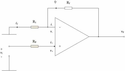
The buffer circuit of unity gain is composed of an integrated operational amplifier and full negative feedback. In order to link a high-impedance source to a low-impedance load without significantly weakening or distorting the signal, buffer circuits are used. The connection method is that the output of the amplifier is connected to the inverting input of the amplifier, Connection Method refers to the technique used to link the main system between the Grid and the Power Plant (or units) and the signal is connected to the non-inverting input. In , when and
are taken, formula (25) is:
From the definition of the input resistance, we know that because of
, so
. Since the input resistance is infinite, the op amp has a very good isolation effect, and it belongs to the negative feedback of voltage sampling. Therefore, its output resistance is
.
Signal buffer circuits implement impedance transformation from one circuit to another. Transformers that match impedance can be utilized in any AC circuit and for any task where maximum power transfer is sought. In audio equipment, microphones, amplifiers, data networks, phone systems, telephone grids, and aviation communication systems, they are frequently used. In this way, the input impedance of the amplifier connected with the lead can be made large enough and the output impedance is small, which can prevent the influence of the input end on the amplifying circuit behind the buffer stage and play an isolation role. Since the output resistance of this stage is the source internal resistance of the subsequent stage circuit, the latter stage amplifier should reduce the source internal resistance to obtain a larger source signal. Connecting a high-impedance source to a low-impedance load without significantly attenuating or distorting the signal is the main purpose of signal buffer circuits. As a result, without loading the source, a buffer’s output voltage replicates its input voltage.
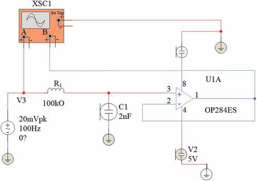
In the system, the OP284ES integrated operational amplifier chip is used to realize the signal buffer circuit, and the Multisim software simulation connection is shown in . Simulation tests are used to evaluate the way individuals respond to and approach difficulties in real-world scenarios. XSC1 is a two-channel oscilloscope in Multisim software, and Multisim is a Windows-based board-level circuit simulation tool launched by National Instruments (NI) Co., Ltd. By using it, the schematic diagram of the circuit can be built interactively and the behavior of the circuit can be simulated. The OP284ES is a dual-channel, single-supply, 4 MHz bandwidth amplifier. It features rail-to-rail input and output, and is guaranteed to operate from+3 V to+36 V (or ±1.5 V to ± 1.8 V), and can operate from a single supply as low as+1.5 V. Furthermore, it is ideal for single-supply applications requiring both AC performance and precision DC performance. When audio and radio signals are sent across electrical cables, AC current is also present. AC current is typically utilized to power houses and businesses. In contrast, DC power is frequently utilized in low voltage applications where Batteries that power flashlights, various home appliances, and some industrial applications frequently use DC current. The combination of bandwidth, low noise, and accuracy makes it suitable for a variety of applications such as filters and instrumentation, including portable telecommunications equipment, power control and protection, and as amplifiers or buffers for sensors with wide output ranges. In addition, by taking advantage of rail-to-rail input and output swings, designers can build multistage filters in a single-supply system while maintaining a high signal-to-noise ratio. Multiple filter stages connected in series or parallel make up multistage filters. when you need to create a filter with an extremely narrow transition width or change the sample rate of a signal by a significant amount. The purpose of multistage filters is to shield the power line from other equipment-damaging electromagnetic interference caused by switching sources.
Figure 5. Multisim simulation of signal buffer circuit.
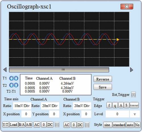
The Multisim simulation result of the signal buffer circuit is shown in . The input signal is a sinusoidal signal with an amplitude of 20 mv and a frequency of 100 Hz. It is drawn with a red line, and the blue line is the output signal. It can be seen that the output signal has the same frequency and amplitude as the input signal, which is consistent with the theoretical value.
Figure 6. Multisim simulation results of signal buffer circuit.
②Design of differential amplifying circuit with in-phase parallel structure
To achieve a high common-mode rejection ratio of a single-integrated op amp, the resistors are required to be strictly matched, and it is not very convenient to adjust the differential mode gain, so the single-op amp differential amplifier circuit must be improved to meet the index requirements. Because differential connections can monitor the difference between the two connected locations and can cancel or ignore common-mode voltages, they are more resistant to EMI than single-ended configurations. The rejected common mode voltages may be noise spikes or constant dc levels. Using resistors that are very closely matched (better than 0.1%) minimizes any variation in the amplification of the signal’s positive and negative sides, which is typically the key to getting a high CMRR. Either raising differential voltage gain or reducing common mode voltage gain will help us increase the CMRR. Emitter resistance RE should be raised to increase CMRR. If the input voltage is input from the non-inverting terminal and the inverting terminal, the input resistance is not high enough. To increase the input impedance, the input signal needs to be sent from the non-inverting terminal. We use to form the first stage of in-phase parallel amplification to improve the input impedance of the amplifier, and
is the second stage differential amplifier.
is the differential input,
is the output of the first stage, according to the symmetrical characteristics of
, the currents in
are equal, and we can obtain:
Thus, we derive that:
The output voltage of the first stage of amplification is:
The first-stage voltage gain is:
In formula (30), there is no common mode voltage. Compared with the formula (11) of the single op-amp circuit, when there is no matching of the external loop resistance, the in-phase parallel connection also has a high common mode rejection ratio. This structure can easily adjust the gain and is easy to use. The first-stage circuit is completely symmetrical, which overcomes the influence of drift and gives full play to the advantages of the symmetrical circuit. Then, it can be derived that if is asymmetric and the common mode rejection ratio is too small, the
of the first-stage amplifier will be reduced. The common-mode rejection ratios are
respectively, and the common-mode input voltage
causes
to have a common-mode error voltage
at its input and
to have a common-mode error voltage
at its input, so the output voltage of the first-stage common-mode error is:
and
The first-stage circuit is:
It can be seen that the difference of the common mode rejection ratio of the devices and
affects the common mode rejection ratio of the first stage amplifying circuit. In order to minimize any variation in the amplification of the negative and positive sides of the signal, it is typically necessary to utilize resistors that are very closely matched (better than 0.1%). To obtain a high common-mode rejection ratio in the first-stage amplifying circuit, Resistor matching is carried out to improve the spacing and arrangement of resistor polygons (process dependant), but shielding is employed to shield essential nets from noisy signal crossings. It only needs to ensure the symmetry of
, and it does not need its own
and
to be high enough. For example, if
and
are
respectively, then
has only
by calculation. If
and
are symmetric and are
and
respectively, then
is 160 dB. Therefore, as long as it is symmetrical, a high common-mode rejection ratio of
can be achieved.
Because the output terminal of has a common mode voltage, the magnitude is equal to the common mode voltage of the input terminal, so only using
is insufficient. This reduces the input range of the differential mode signal. So, connect the amplifier at the back, as shown in . The gain in is:
The total common mode output is:
The resulting common mode gain is:
The overall CMRR is:
Among them, is determined by formula (17) and formula (24), and
is determined by formula (34).
It can be seen from formula (38) that the common mode rejection capability depends on: the degree of symmetry of and
, the common mode rejection ratio of
, the closed-loop gain and
matching accuracy, and the first-stage differential gain. When the first level has good symmetry,
Formula (38) can be approximated as
That is, the common mode rejection ratio is determined by the gain of the front stage and the common mode rejection ratio of the subsequent stage.
Application of Behavioral Psychology in Apparel Design
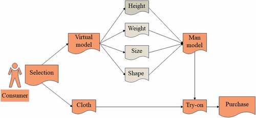
Through the intelligent behavioral psychological quantitative processing method proposed above, The Quantitative design determine the proportion of persons to hold a given belief, behavior, or emotion. Large sample sizes are common in focussing on the volume of replies rather than the more complex understanding. Descriptive, correlation, causal-comparative, and experimental research are the four main subtypes of quantitative research. The application of clothing design is analyzed, and the effect of clothing design is improved by intelligent means. Combined with the actual situation, the effect of clothing design is improved. shows the intelligent clothing design system designed in this paper.
Figure 7. Apparel design based on behavioral psychology.
In this paper, the system performance verification is carried out with the support of the system. By determining the issue and select a research question, Launch a literature review and examine the available literature, choose a theoretical framework that will guide your research and develop a hypothesis. The system of this paper is developed through the quantitative design method of behavioral psychology. Therefore, in this paper, Matlab is used as the simulation platform, and the effect of the model proposed in this paper is verified by placing the design method. In the process of experimental research, this paper visually displays through the design example diagram, and evaluates the effect of the model proposed in this paper. In addition, combined with mathematical statistics, the evaluation data is visually displayed. It offers a framework of skills and knowledge that have been chosen to be suitable for a certain level.
Results
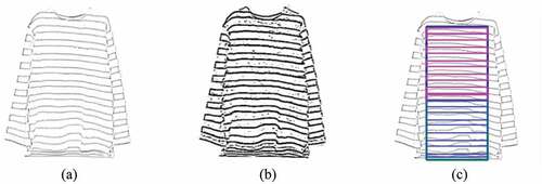
With the support of the intelligent system in this paper, a computationally intensive system that can gather, examine, and react to the information it gathers from its surroundings is an intelligent system. With other entities, such as people or other computer systems, it can operate and communicate. The quantitative analysis of user behavior psychology is carried out through the intelligent platform, and the clothing design is carried out, Clothing design is greatly influenced by psychology behavior since it enables designers to understand users. Complex in nature, clothing psychology draws on a wide range of facets of the human experience, including neurobiology, sexuality, culture, and symbolism are the factors that influence the design system and the example image shown in is obtained.
Figure 8. Example image of clothing. (a) Clothing texture decoration, (b) Clothing texture enhancement, (c) Clothing color rendering.
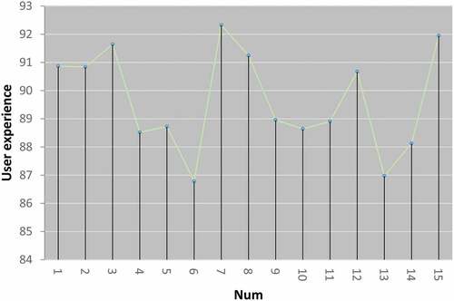
The clothing simulation effect and user satisfaction of the clothing design system in this paper are evaluated and analyzed. With the use of collision, gravity, air friction, human movement (including bending, stretching, and moving), and simulation software, you may control clothing. Whereas simulations encourage the application of analytical and critical thinking, the precision of their forecasts is quite trustworthy and aids in problem identification. Then, it serves as a measure for the way a company’s goods and services acts that way to consumer expectations. Good quality guarantees increased client satisfaction and a higher likelihood of ongoing collaboration and the results shown in are obtained.
Figure 9. Clothing simulation effect based on quantitative analysis of intelligent behavior psychology.
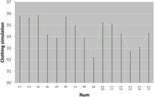
Figure 10. User experience of clothing design based on quantitative analysis of intelligent behavioral psychology.
Discussion
The system of this paper is developed through the quantitative design method of behavioral psychology. Therefore, in this paper, Matlab is used as the simulation platform, and the effect of the model proposed in this paper is verified by placing the design method. Through behavioral psychology, user preferences can be automatically evaluated. In this paper, the improvement of intelligent algorithms can effectively improve the recognition effect of behavioral psychology, and can effectively improve the real-time control of user needs.
Through , the psychology of user behavior can be linked with the style and color of clothing decoration, which effectively changes the subjectivity of designers in clothing design. Moreover, it allows users to participate in the clothing design process, and truly realizes a user-oriented clothing design system.
As can be seen from , the quantitative analysis of clothing design effect based on intelligent behavior psychology proposed in this paper can simulate clothing according to the user’s psychology. Therefore, on the basis of not improving the image simulation effect, the clothing simulation effect can still be improved, which is closely related to the accurate identification of user behavior psychology.
It can be seen from that the quantitative analysis method of clothing design based on intelligent behavior psychology proposed in this paper can effectively improve the user experience, and truly achieve an effective improvement on the basis of traditional clothing design from the perspective of user needs and user satisfaction.
Conclusion
Clothing behavior is the externalized form or manifestation of human psychology, and an individual’s clothing behavior is the manifestation of their psychological characteristics or psychological state at that time. If there was only one person in the world, there would be no clothing behavior. Because the world is made up of many people and everyone is in a society, there are great social constraints on human behavior. Therefore, clothing behavior is expressed in both social and individual attitudes. Based on behavioral psychology theory, this paper studies the color trend of fashion clothing, and analyzes the interaction between color trend in each link of clothing design and other design elements. Moreover, this paper applies the relevant theories of behavioral psychology to the color design of fashion clothing, which can help designers to design more comprehensively. Finally, through experimental research, it is verified that the clothing design system based on behavioral psychology proposed in this paper can effectively improve the effect of clothing design and enhance the user experience.
Recommendations
By analyzing, understanding, and clarifying the fitting psychology of clothing users in the process of purchasing clothes, and through the quantitative identification of user behavior psychology through the intelligent platform, we design the system completely according to the actual needs of clothing users. At the same time, it is necessary to think from the perspective of users, what kind of online fitting system they need. The first is to ensure that the difference between the realization and the virtual is small, and the user has a sense of reality. The second is to ensure that the quality of clothing is guaranteed, so that people can buy with confidence. The third is the rich variety of species. The greater the choice for users, the better, so that users have a sense of achievement in the design process.
In the follow-up research, the system in this paper should be further verified with practical experiments, and an online intelligent behavioral psychological testing platform can be established in the process of clothing design to improve the effect of users designing clothing online.
Acknowledgements
Shaanxi social science fund project, “A study on military uniform culture in Han Dynasty” (2019K032).
Disclosure statement
No potential conflict of interest was reported by the author.
Additional information
Funding
References
- Abdullajonovna, R. M., S. F. A. Kizi, and M. G. Khayitovna. 2021. Expert analysis of the quality of materials for special clothing. JournalNx 7 (03):399–1147.
- Black, C., C. Freeman, and A. Rawlings. 2018. Problem-based learning: Design development of female chef’s jackets. International Journal of Fashion Design, Technology and Education 11 (1):123–28. doi:10.1080/17543266.2017.1332245.
- Gill, S., and C. J. Parker. 2017. Scan posture definition and hip girth measurement: The impact on clothing design and body scanning. Ergonomics 60 (8):1123–36. doi:10.1080/00140139.2016.1251621.
- Jasiuk, I., D. W. Abueidda, C. Kozuch, S. Pang, F. Y. Su, and J. McKittrick. 2018. An overview on additive manufacturing of polymers. Jom 70 (3):275–83. doi:10.1007/s11837-017-2730-y.
- Jin, B. E., and D. C. Shin. 2021. The power of 4th industrial revolution in the fashion industry: What, why, and how has the industry changed? Fashion and Textiles 8 (1):1–25. doi:10.1186/s40691-021-00259-4.
- Kim, S. Y., and J. Ha-Brookshire. 2019. Evolution of the Korean marketplace from 1896 to 1938: A historical investigation of Western clothing stores’ retail and competition strategies. Clothing and Textiles Research Journal 37 (3):155–70.
- Mackey, A., R. Wakkary, S. Wensveen, and O. Tomico. 2017. “Can I Wear This?” Blending clothing and digital expression by wearing dynamic fabric. International Journal of Design 11 (3):51–65.
- Miell, S., S. Gill, and D. Vazquez. 2018. Enabling the digital fashion consumer through fit and sizing technology. Journal of Global Fashion Marketing 9 (1):9–23. doi:10.1080/20932685.2017.1399083.
- Milošević, P., and S. Bogović. 2018. 3D technologies in individualized chest protector modelling. Textile & Leather Review 1 (2):46–55. doi:10.31881/TLR.2018.vol1.iss2.p46-55.a6.
- Park, J., K. Park, B. Lee, H. You, and C. Yang. 2019. Classification of upper body shapes among Korean male wheelchair users to improve clothing fit. Assistive Technology 31 (1):34–43. doi:10.1080/10400435.2017.1335359.
- Starkey, S., S. Alotaibi, H. Striebel, J. Tejeda, K. Francisco, and N. Rudolph. 2021. Fashion inspiration and technology: Virtual reality in an experimental apparel design classroom. International Journal of Fashion Design, Technology and Education 14 (1):12–20. doi:10.1080/17543266.2020.1844807.
- Zhao, Y. 2018. Manufacturing personalization models based on industrial big data. Journal of Discrete Mathematical Sciences and Cryptography 21 (6):1287–92. doi:10.1080/09720529.2018.1526403.