
 ?Mathematical formulae have been encoded as MathML and are displayed in this HTML version using MathJax in order to improve their display. Uncheck the box to turn MathJax off. This feature requires Javascript. Click on a formula to zoom.
ABSTRACT
The precise control of a complex hydraulic drive system, which is mostly dependent on the speed control of the system working shaft, contributes to an improvement in product quality. In this paper, a novel working shaft speed control method for complex hydraulic drive system is proposed. First, a mathematical model of the operation of the working shaft and related components is established, and the fuzzy PID controller is designed to regulate the working shaft speed of the complex hydraulic drive system based on fuzzy rules. A whale optimization algorithm improved by intuitionistic fuzzy entropy is proposed to optimize the parameters of fuzzy PID controller in light of the possibility that the selection of parameters of fuzzy PID controller will have an impact on the final control effect. By applying an improved fuzzy PID controller to fit working shaft speed of three complex hydraulic drive system, the control performance of the controller is evaluated. The experimental results demonstrate that the tracking accuracy and immediate efficiency of the proposed method for working shaft speed control of the complex hydraulic drive systems are significantly better than those of the fuzzy PID controller and the fuzzy PID controller optimized with the unimproved whale optimization algorithm, proving the proposed method has strong engineering practical application capacity and can more effectively fulfill the working shaft speed control needs of the complex hydraulic drive system.
Introduction
Hydraulic drive systems have been widely used in computerized numerical control (CNC) machine tools (Chen et al. Citation2021). Hydraulic cylinder, hydraulic pump, hydraulic motor, control valve, and oil pipe are the key components of complex hydraulic drive system. As the complex hydraulic drive system uses gasoline as its energy source and a hydraulic pump to transform mechanical energy into pressure energy, a range of driving actions may be carried out. If the working shaft speed is unstable when the hydraulic drive system is in use, it will not only consume too much fuel but also seriously damage the system (Shin et al. Citation2021). As a result, precise control of the working shaft speed of the hydraulic drive system can enhance the stability of the hydraulic system and significantly raise the accuracy and quality of the output. Both academics and industries have done extensive research on the strategy for controlling the working shaft speed of the hydraulic drive system up to this point (Wang et al. Citation2019; Zeng et al. Citation2021). With the swift advancement of electro-hydraulic technology comes an improvement in the regulation of the working shaft of the hydraulic drive system, which gradually aids in the intelligent expansion of the road.
In general, the study of complex systems tends to be approached from both modeling and algorithmic aspects (Dan et al. Citation2021, Citation2021; Wu et al. Citation2021; Z. L. Zhang et al. Citation2019). Using a power split hydraulic transmission cooling fan drive system as an example, Wang et al. (Citation2022) performed research on the control design. Furthermore, a feedforward controller based on transmission parameters was developed to improve system performance. To assess system control design, a hydraulic fan drive test bench has been created. Simulated and actual studies were used to compare the dynamic performance of feedforward and feedback control systems. Zhu et al. (Citation2020) proposed a mathematical model for the drive system of a high clearance hydraulic tracked vehicle which was developed by analyzing its structural characteristics and dual pump dual-motor drive system. A control strategy was also formulated using quantitative feedback theory to enhance the control accuracy of the drive system and improve its precision.
The proposed control strategy was effectively implemented, allowing for the achievement of the goal of achieving robust control of the hydraulic tracked vehicle drive system. Hao et al. (Citation2022) proposed an electromechanical hydraulic hybrid actuator (EMHA) prototype and a hydraulic electric hybrid linear drive principle that integrates hydraulic cylinders and EMA in order to achieve high efficiency, high power-to-weight ratio, and high-performance linear drive. In the hybrid drive system, the actuator’s motion is managed by EMA, while force control is handled by hydraulic cylinders. This system can offer control performance comparable to valve control systems while consuming 58% less energy. Wei et al. (Citation2023) principally concentrate on tracking control using singular perturbation theory (SPT) for hydraulic-driven flexible robotic manipulator system (HDFRMS) with different payloads and uncertainties. Wang, Bo, and Meng (Citation2002) conducted an experimental study of the pressure discharge process from the stepped cylinder of the Hydraulic Control Rod Drive System (HCRDS) for the 200 MW Nuclear Heating Reactor (NHR-200). According to the findings, the pressure disparity within the stepped cylinder rapidly increased to the appropriate level, generating enough force to move the outer tube of the cylinder. In case the hydraulic control rod gets stuck, the pressure can assist in overcoming friction and inserting the control rod into the reactor core. The test results validate the effectiveness of this design in preventing hydraulic control rod jamming during accidents.
While much current research on the control technology of complex hydraulic drive systems is conducted from a holistic point of view, carefully examining the relationships between the system’s numerous components, it frequently overlooks the study of individual components’ control strategies. Despite being crucial to the operation of complex hydraulic drive systems because of their unique construction, the working shaft has received relatively little attention in the literature. Shi et al. (Citation2019) concentrated on theoretical modeling and experimental research on the temperature control of screw shaft and the interaction between heat generation and heat dissipation but did not study the mechanical control technology of screw shaft in this paper due to the cooling effect of forced fluid circulation on the ball screw feed drive system of precision boring machine. In order to lessen the impact of cutting forces on controlling the speed of the hydraulically driven shaft, Hayashi and Nakao (Citation2018) presented the development of a speed control system, examined the mathematical model of a hydraulically driven spindle and a flow control valve, developed a feedback control system, and added a disturbance observer to the designed feedback control system.
Wang and Stelson (Citation2015) investigated an effective hydraulic pressure-controlled transmission (PCT)–based fan driving system. The new gearbox uses a floating ring, double acting vane pump. The vane pump is transformed into a hydraulic transmission device by coupling the floating ring to the output shaft. The novel gearbox is substantially simpler than conventional hydrostatic transmissions (HSTs) since it integrates pumping and driving duties into a single element. With a focus on examining the impact of control pressure on the output shaft torque, it is possible to modify the torque and speed of the output shaft by adjusting the pressure in PCT. A new transmission was fitted to the fan drive system to show off its benefits, and its transmission efficiency was compared to HST.
Although the aforementioned method has some effect on controlling the working shaft speed of the complex hydraulic drive system, accurate control of the working shaft speed is difficult to achieve because the control parameters are not adaptive in their control process. In this regard, this paper builds a theoretical model for the working shaft control of a complicated hydraulic drive system and examines the operation of the speed control system for the working shaft transmission group. The complex hydraulic drive system’s automatic transmission and control components are supplied with a mathematical description, and the structural parameters of the system are described. The range of the PID control parameter set is then established, followed by the development of a fuzzy PID controller. The fuzzy PID controller parameters are then optimized using a whale optimization algorithm (WOA) that has been improved by intuitionistic fuzzy entropy (IFE). On Matlab/Guide software, the speed is controlled using an optimized fuzzy PID controller. The efficiency of the PID controller design, which is based on an IFE-WOA improvement, is assessed by studying the control outcomes.
The motivation for this paper is to address the challenge of controlling the working shaft speed in complex hydraulic drive systems. These systems are used in a wide range of industrial applications, such as in manufacturing, construction, and transportation. Precise control of the working shaft speed is crucial for ensuring high product quality, safety, and efficiency in these applications. However, due to the complexity of hydraulic drive systems and the various factors that can affect the working shaft speed, achieving precise control can be challenging.
This paper aims to develop a novel method for controlling the working shaft speed in complex hydraulic drive systems. The proposed method is based on a fuzzy PID controller, which can regulate the working shaft speed and account for the uncertainty and imprecision in the system. The use of a whale optimization algorithm improved by intuitionistic fuzzy entropy allows for the optimization of the controller’s parameters, which can further enhance control performance.
Overall, the motivation for this paper is to provide a practical and effective solution for controlling the working shaft speed in complex hydraulic drive systems. The proposed method has the potential to improve product quality and efficiency in various industrial applications, making it a valuable contribution to the field.
Mathematical Model Analysis of the Working Shaft of the Complex Hydraulic Drive System
The load producing module, the working shaft, the hydraulic motor, and the triangular belt mechanism make up the speed control system of the transmission group of the working shaft of a complicated hydraulic drive system. In this arrangement, a triangular belt mechanism powers the three-phase motor. In this configuration, the oil pump gear is driven by a three-phase motor through a triangular belt arrangement. Relief valves and safety valves control the operating pressure and prevent overflow. The speed of the hydraulic motor is controlled by an oil valve, which is managed by a proportional valve. The oil line that links the pump to the proportional valve features a high-pressure filter and a battery that collects and balances the oil’s potential energy. Additionally, the triangular belt transmits the rotation from the hydraulic motor to the working shaft. The working shaft’s speedometer functions as a speed sensor for detecting speed and receives the working shaft’s speed from the drive belt. Additionally, the pressure level can be altered by using relief valves and safety valves.
illustrates the structure of the automatic drive and control segment in the complex hydraulic drive system. This particular component manages the elastic deformation of the drive belt from the rotation axis of the hydraulic motor to the working shaft, as well as the friction and moment of inertia on the rotor of the hydraulic motor. showcases the main parameters that are involved in this process.
Figure 1. The structure of the automatic drive and control part of the complex hydraulic drive system.
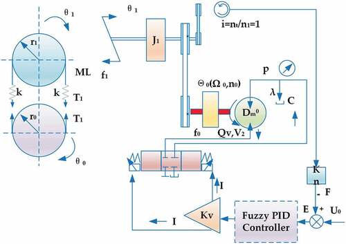
Table 1. The main parameters involved in the complex hydraulic drive system.
Based on the relationship between the mechanisms in the automatic transmission and control part of the hydraulic system shown in and the requirements of the system dynamics, the mathematical model on the working shaft and the related mechanism of the hydraulic motor can be derived, as expressed below.
The torque on the working shaft is expressed as:
In EquationEquation 1(1)
(1) ), ML is the load on the working shaft.
T1 and T2 are calculated as
The feedback value F of the speed sensor is calculated as:
kn is the gain of the speed sensor. In the case of hydraulic motors, T1, T2, and r0 can be used to find the hydraulic equation of the torque of the motor rotor.
The flow equation of the hydraulic motor can be found by Dm.
In EquationEquation 6(6)
(6) , Q is the flow rate through the hydraulic motor and c is the modulus of elasticity per unit volume of fluid, which can be calculated as follows:
V1+V2 is the total volume of the oil in the pipe. B is the bulk modulus of the oil.
The proportional valve’s valve flow gain Kv may be used to determine Q without taking into account the flow loss of the valve.
The combination of EquationEquations (1)(1)
(1) -(Equation5
(5)
(5) ) shows that
Working shaft speed is
The feedback value F of the speed sensor is used to obtain the input of the controller E.
Combining EquationEquations (4)(4)
(4) -(Equation12
(12)
(12) ), the equation of state of the complex hydraulic drive system can be obtained as
In EquationEquation (13)(13)
(13) , s is the frequency domain parameter.
Fuzzy PID Controller Design Based on IFE-WOA Improvement
Fuzzy PID Controller
Basic Concept
According to Section 2, the automated transmission and control process of the complex hydraulic drive system is a closed-loop process, and the system state equation reveals that the working shaft speed control process is a nonlinear dynamic process. Therefore, in this research, the fuzzy PID controller is used to regulate the speed of the working shaft of the complex hydraulic drive system in order to overcome the nonlinearity of the control process and to adapt to the control needs of the closed-loop system (Ab Talib et al. Citation2023).
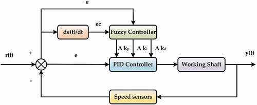
By integrating the benefits of both control systems, fuzzy PID control is a technique that applies fuzzy control theory to PID control (Zhang and Li Citation2022). The fuzzy PID controller addresses the limitations of traditional PID control parameters, which cannot be adjusted in real time and the poor steady state of fuzzy control. It also solves the issue of needing an accurate mathematical model for the control object. This controller utilizes the deviation value e and deviation rate ec between the desired value r(t) and the actual value y(t) of the complex hydraulic drive system’s working shaft as input variables. Then, the three parameters kp, ki, and kd, are produced after fuzzy processing, which can then be used to adaptively adjust the PID control parameters to achieve speed control of the working shaft of the complex hydraulic drive system. The principle of using fuzzy PID control to control the working shaft speed of a complex hydraulic drive system is shown in .
Figure 2. The principle of using fuzzy PID control to control the working shaft speed of a complex hydraulic drive system.
Determination of Input and Output Quantities and Affiliation Functions
The process of obtaining the fuzzy relationship equation and determining the fuzzy control quantity is inference. Through this process, the fuzzy set can be determined and needs to be clarified. Reasoning may be used to determine the fuzzy set, and in order to get the precise control quantity, it has to be clarified, or defuzzified. The interface for defuzzification is referred to as the interface that might lead to an explanation. In this study, the control quantity is exactly determined using the center of gravity method. The equation for calculating the precise control amount using the center of gravity approach is:
Δkp, Δki, and Δkd are the updated parameter variables of fuzzy PID control, and the corresponding inputs are denoted as kij, which can be found from row i and column j of the fuzzy rule table. The output is denoted as Δk, and the affiliation degrees relative to the fuzzy PID inputs ec and Δkn are denoted as kec and Δkdn, respectively.
The adjustment equation of the control parameters is:
kp, ki, and kd denote the parameters after regulation, and kp0, ki0, and kd0 denote the parameters before regulation.
In this study, a fuzzy PID controller is used to regulate the working shaft speed of the complex hydraulic drive system. The deviation value e and the rate of change of deviation ec between the given value r(t) and the actual value y(t) of the working shaft speed are set as input variables. In addition, the changes of control parameters Δkp, Δki, and Δkd are set as output variables. Thus, the corresponding fuzzy quantities are set as E, EC, ΔKp, ΔKi, and ΔKd, and the fuzzy subsets of linguistic values are divided into seven fuzzy sets as shown in .
Table 2. Fuzzy set partition of linguistic values.
Affiliation functions vary depending on the magnitude of the input and output variables. When the input and output variables are PB or NB, the Z- and S-shaped affiliation functions are utilized; in all other situations, the triangle affiliation function is used.
Based on the collective knowledge of pertinent subject matter experts and personnel, the fuzzy rule base is developed. The established criteria are.
The system should have a quick dynamic response, so ΔKp should take a large value, but ΔKi and ΔKd should take a small value to prevent over-adjustment. This is because a large input error E of the fuzzy controller indicates a large gap between the input and output of the system.
The output of the system has not yet achieved the optimal state when the input error E of the fuzzy controller is somewhat big. To avoid a significant overshoot and guarantee that the system performs superbly under dynamic conditions, ΔKi and ΔKd should be greater in this scenario, while ΔKp should be smaller.
To maintain the stability of the system, ΔKp and ΔKi should be bigger when the input error E of the fuzzy controller is small, indicating that the system has a good control effect. The size of ΔKd should be correctly determined to ensure the stability of the system.
Experiments were conducted on the automated drive and control part of the complex hydraulic drive system using the classical PID controller, and the calculated values of the PID controller parameters at various temperatures are generated. It is discovered through studies that,
and
.
The fundamental theoretical domains of E and EC, as determined by several experiments on the PID set, are as follows [−60, 60] and [−500, 500], respectively. The fuzzy subsets of ΔKp, ΔKi, and ΔKd are set as (17MB, B), and the range of this fuzzy subset is [0,1]. The fuzzy rules of ΔKp, ΔKi, and ΔKd are formulated as shown in , respectively. At this point, the affiliation function curves of E, EC, ΔKp, ΔKi, and ΔKd are obtained, as shown in .
Figure 3. The affiliation function curves of E, EC, ΔKp, ΔKi and ΔKd.
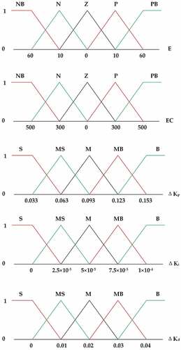
Table 3. Fuzzy rules of ΔKp.
Table 4. Fuzzy rules of ΔKi.
Table 5. Fuzzy rules of ΔKD.
The five parameters E, EC, ΔKp, ΔKi, and ΔKd have conflicting regulatory effects. In addition to thoroughly taking into account each parameter’s effect while altering them manually, it is also crucial to take into account the elements that affect the parameters in concert. As a result, it is essential to understand the key elements of parameter modification and make several adjustments. It follows that it is time-consuming and difficult to manually alter the fuzzy PID controller’s settings. In order to achieve a better control performance, the improved whale optimization algorithm based on intuitionistic fuzzy entropy is introduced in this study. The parameters of the fuzzy PID controller are then optimized using offline simulation tests in accordance with the particular working conditions and data of the complex hydraulic drive system.
Parameter Optimization of IFE-WOA Based Fuzzy PID Controller
Whale Optimization Algorithm (WOA)
The WOA algorithm is unique in its approach to problem-solving. Unlike other algorithms, it utilizes a combination of random search and mimicking the population’s foraging behavior using the best individual. The algorithm comprises three primary stages: encircling predation, bubble net attack, and search foraging, which are detailed in the following section (Dong et al. Citation2023).
(1) Encircling predation
According to the WOA, the most suitable solution in the population is considered the best candidate solution. Once identified, the population will reach the optimal outcome as per EquationEquation 1(1)
(1) .
is the position vector of the prey, t is the number of current iterations, and A, C are the coefficient vectors determined by EquationEquation 18
(18)
(18) and EquationEquation 19
(19)
(19) .
where ra1 and ra2 are the random numbers between [0,1], a is the convergence factor for the linear decrease from 2 to 0, and Max_iter denotes the maximum number of iterations.
(2) Bubble net attack
Shrinking encirclement: This is achieved by reducing the convergence factor a in EquationEquation 20(20)
(20) , and the value of a decreases with the number of iterations so that the individual whale continuously updates. The position factor approaches the prey to complete the envelopment.
Spiral update: As individual whales hunt for prey, they use an upward spiral approach to align themselves with their target. This approach can be represented by EquationEquation 21(21)
(21) in a mathematical model.
The variable D′ represents the distance between the prey and the individual, while b is a constant that determines the spiral search’s shape. The letter l represents a random number within the range of −1 to 1.
When |A|≤1, the bubble net attack is used with a probability of 50% each in performing shrink-wrap and spiral update. The mathematical model is shown in EquationEquation 23(23)
(23) when p < .5 for contraction envelopment and vice versa for spiral update (Pham, Chon, and Ahn Citation2023).
(3) Search foraging
In contrast to the contraction and encirclement stage, when |A|>1, an individual is randomly selected in the population to search for preference. The mathematical model is shown below:
Xrand is the position vector of the randomly selected individuals.
Improvement of WOA Based on Intuitionistic Fuzzy Entropy (IFE)
In contrast to fuzzy sets, intuitionistic fuzzy sets include a non-subordinate degree function, which can more accurately depict the nature of fuzzy objects in the real world. In dealing with uncertain and partial information, it has higher expressive and discriminative capabilities when compared to other information theoretic approaches.
This inherent property of IFE makes it possible for IFE to more sensitively depict the information carried by each person when they are operating, which facilitates the high-precision series computation of metaheuristic algorithms and enhances the correctness of the solution. This study reconstructs the intuitionistic fuzzy population entropy and leverages the historical best solution information of the population individuals to create the intuitionistic fuzzy entropy in order to more effectively depict the convergence state and energy change of the population. By reconstructing the intuitionistic fuzzy population entropy and designing the adaptive function of intuitionistic fuzzy entropy using the historical best solution information of the population individuals, we are able to more accurately reflect the convergence state and energy change of the population. We also use the entropy value as a perturbation factor to dynamically change the inertia weight, which increases the likelihood of population diversity and uniform distribution. In this study, we define a scope of radius Ri centered on the location of historically optimal individuals in each generation and show that all individuals within this scope are clustered around this location; however, all individuals outside of this scope are referred to as orphan points.
The intuitionistic fuzzy entropy is a measure of uncertainty or fuzziness in the intuitionistic fuzzy sets (IFSs). It can provide a more accurate assessment of the degree of uncertainty in the IFSs than traditional fuzzy entropy. The WOA is a metaheuristic optimization algorithm inspired by the hunting behavior of whales. It is commonly used for solving optimization problems, including parameter optimization of fuzzy PID controllers.
In this paper, intuitionistic fuzzy entropy is used to improve the WOA for optimizing the parameters of the fuzzy PID controller in the complex hydraulic drive system. The intuitionistic fuzzy entropy is incorporated into the fitness function of the WOA to enhance its exploration and exploitation capabilities. Specifically, the proposed WOA algorithm calculates the entropy of the intuitionistic fuzzy sets associated with each whale in the population and uses this information to update the search process.
By using intuitionistic fuzzy entropy, the WOA algorithm can better account for the uncertainty and imprecision in the optimization problem. This can lead to more accurate and effective parameter optimization for the fuzzy PID controller, which can ultimately improve the control performance of the complex hydraulic drive system. The experimental results presented in this paper show that the proposed WOA algorithm improved by intuitionistic fuzzy entropy outperforms the traditional WOA algorithm in terms of convergence speed and optimization performance.
Definition 1:
Defining the i-th individual in the D-dimensional space denoted as . Taking the historically optimal individual in each generation as the centroid k (k = 1, 2, … , n), calculating the distance from each individual to the centroid, denoted
. Defining Radius
, and K is a random number in the range [0, 0.5].
Definition 2:
In the t-th generation, if is smaller than Ri, the individual is considered to be in the field of radius Ri, and the counter Ti is set plus 1. If
is smaller than Ri, the individual is called an “orphan”, and the global counter Tx is set plus 1.
denotes the degree to which an individual belongs to the historically optimal position in the t-th generation,
denotes the degree of hesitation, and
denotes the degree to which an individual does not belong to the historically optimal position.
Definition 3:
The IFE of the population in the t-th generation is defined as and n is the population size, then:
The algorithm’s functioning depends heavily on the inertia weight, which balances capabilities of WOA for both local and global exploitation. The magnitude of the intuitionistic fuzzy entropy value shows the level of population aggregation that is currently present. Individuals are generally spread, population diversity overall is high, the degree of aggregation of individuals is low, and the entropy value is high at the early stages of algorithm operation, when the algorithm is in the global search stage. At later stages of the algorithm, behavior of all individuals tends to stagnate, degree of aggregation of individuals is largest, population diversity is smallest, and entropy value decreases to the smallest. As the algorithm operates, the particles continue to move toward the optimal point, the degree of aggregation increases, the population diversity decays, and the entropy value decreases. In order to adaptively modify the balance between the global exploration capabilities and local fine search of WOA, the entropy value is employed in this research as a perturbation factor and the inertia weight is dynamically modified with the number of iterations and entropy change approach. The following are adjustments to the inertia weight:
ωmax and ωmin are the initial and final values of inertia weights, respectively, t is the number of current iterations, and Et is the magnitude of the current population’s IFE value. Since , ω decreases gradually from ωmax to ωmin as the number of iterations increases, which helps the algorithm to perform global search when ω is large and local search when ω is small. In this paper, ωmax = 0. 9 and ωmin = 0. 4. The position update equation of WOA after introducing ω is as follows:
The WOA has a linear convergence rate, which limits its ability to perform effective global and local searches. It is prone to getting stuck in local optima during the search process. To address this issue, the algorithm has been improved with the introduction of ω, which modifies the convergence factor a. This modification allows for nonlinear convergence that decays faster during the initial search period, ensuring that the optimal solution range is reached. During the second period, the decay rate slows down, resulting in enhanced local search and improved convergence accuracy. EquationEquation 31(31)
(31) shows an updated expression of the nonlinear factor.
ainitial and afinal are the initial and final values of a, respectively.
The performance of the fuzzy PID controller is not only related to the fuzzy rule base but also closely related to the selection of parameters. In this study, the parameters of the fuzzy PID controller are optimally selected by applying IFE-WOA on the basis of the complex hydraulic drive system model built by invoking the whale position corresponding to the values of the parameters, and the specific steps are as follows:
Determine the initial population, according to the actual situation, 20 was set as the initial population number in this study.
Determine the optimal range of the parameters.
Determine the fitness function. In this study, the time multiplied absolute error integration criterion, which can comprehensively evaluate the response time, overshoot, and other dynamic and static characteristics of the control system, is used as the fitness function, and the expression is shown below:
(31)
Run the IFE-WOA in Matlab and output the optimized parameter values.
Run the simulation model of complex hydraulic drive system in Simulink, evaluate the optimized parameters using the fitness function, and go to step (4).
After reaching the maximum number of iterations, the study outputs the global optimal solution. In this particular study, the maximum number of iterations is set to 500.
Experimental Analysis
A PC with Intel I7 CPU and 16GB memory is used as the hardware platform and MATLAB/Simulink software is used as the software platform to build a simulation model according to the main parameters shown in Section 2, which is used to verify the effectiveness of the proposed method for speed control. The fuzzy PID controller is used for experimental to facilitate better observation of the control results.
The paper did not compare the proposed method with other existing control methods for several logical reasons.
First, the focus of this paper is on proposing a novel method for controlling the working shaft speed in complex hydraulic drive systems. This paper presents a comprehensive approach for optimizing the parameters of the fuzzy PID controller using the whale optimization algorithm improved by intuitionistic fuzzy entropy. This paper evaluates the proposed method through experiments on three complex hydraulic drive systems. This approach provides a detailed and practical solution for controlling the working shaft speed in complex hydraulic drive systems, and it is not necessary to compare the method with other existing control methods.
Second, comparing the proposed method with other existing control methods would require a comprehensive review and analysis of the existing literature. This would require a significant amount of time and effort to perform, and it is not within the scope of this paper. Moreover, the literature on control methods for complex hydraulic drive systems is vast and diverse, and it is difficult to compare the proposed method with all the existing methods.
Finally, the proposed method utilizes a combination of fuzzy PID control and optimization algorithms, which is a unique and original approach to the problem of controlling the working shaft speed in complex hydraulic drive systems. Therefore, the paper can stand on its own as a contribution to the field without comparing it to other existing control methods.
Response Sensitivity Test
Setting 3 target speeds of 200, 400, and 600 r/min. The IFE-WOA-based improved fuzzy PID controller proposed in this paper and fuzzy PID controller are used to track the set 3 target speeds. The tracking results of the IFE-WOA-based improved fuzzy PID controller and fuzzy PID controller are analyzed to analyze the response sensitivity of each method. shows the results of tracking the three target speeds using the two methods.
Figure 4. Response sensitivity test results: (a) IFE-WOA-based improved fuzzy PID controller; (b) Fuzzy PID controller.
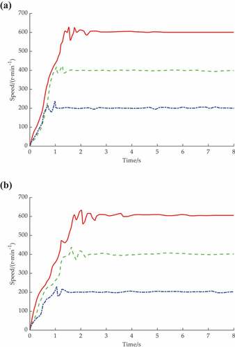
As can be seen in , the three target speeds of 200, 400, and 600 r/min are reached at t 0.82 s, 1.02 s, and 1.48 s, respectively, when the IFE-WOA-based improved fuzzy PID controller is used to track the three target speeds. After a short adjustment, they are stabilized at 1.15, 1.72, and 2.39 s, respectively. In contrast, the three target speeds of 200, 400, and 600 r/min were reached at t 0.99 s, 1.82 s, and 1.95 s, respectively, and were stabilized at 1.48 s, 2.41 s, and 2.89 s, respectively, after adjustment by the fuzzy PID method. This shows that the IFE-WOA-based improved fuzzy PID controller has higher response sensitivity and can respond to the speed variation requirements faster.
Random Variation Speed Tracking Test
In order to test the tracking accuracy of two types of working shaft speed, two types of randomly varying working shaft speed were set for tracking, and the velocity tracking results are shown in .
Figure 5. Random variation speed tracking test results: (a) IFE-WOA-based improved fuzzy PID controller; (b) Fuzzy PID controller.
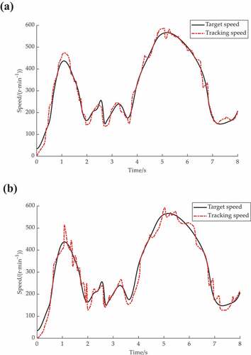
From , it can be seen that the IFE-WOA-based improved fuzzy PID controller tracks the randomly variation speed with the maximum deviation from the target speed around 1.1 s, and the deviation is about 9% at this time; after adjustment, the IFE-WOA-based improved fuzzy PID controller tracks the target speed again around 1.3 s, and the subsequent deviation is about 9%. After adjustment, the IFE-WOA-based improved fuzzy PID controller tracks the target speed again around 1.3 s, and there is only one large deviation in the subsequent tracking of the target speed. From , it can be seen that the fuzzy PID controller tracked the randomly variation speed with only one large deviation around 1 s. After the adjustment, the fuzzy PID controller tracks the target speed around 1.5 s, but there are three large deviations in the subsequent tracking of the target speed. This shows that the IFE-WOA-based improved fuzzy PID controller has a better tracking performance for the randomly variation speed.
To further observe the control performance of the two methods, the input signals of the two methods are compared by tracking the randomly variation speed. shows the variation of the input signals of the two methods in tracking the randomly variation speed.
Figure 6. Tracking input signal variation at randomly varying speeds.
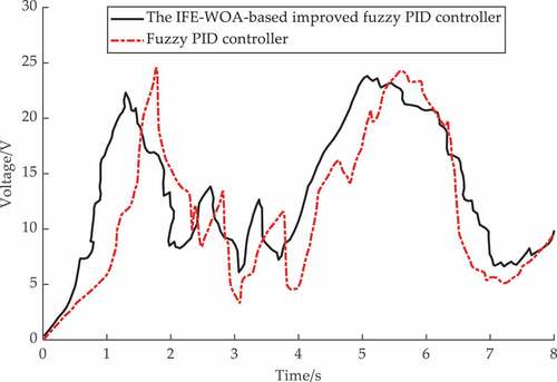
From , the input signal of the IFE-WOA-based improved fuzzy PID controller can respond quickly according to the change of the target speed, and the number of oscillations of the whole tracking process is less. The input signal of the fuzzy PID controller is sluggish and cannot respond quickly to the change of the target speed, and the whole tracking process has more oscillations. Thus, the IFE-WOA-based improved fuzzy PID controller is not only able to track the target speed accurately but also responds faster when the target speed changes.
Discussion and Conclusions
The method proposed in this paper aims to control the working shaft speed of complex hydraulic drive systems using a fuzzy PID controller optimized by a whale optimization algorithm improved by intuitionistic fuzzy entropy. The method consists of three main steps: mathematical modeling, controller design, and optimization.
In the first step, the mathematical model of the working shaft and related components is established, based on the physical laws governing the hydraulic system. The model takes into account the hydraulic pressure, flow rate, and other relevant parameters, and describes the dynamics of the system in terms of differential equations.
We have designed a fuzzy PID controller for the second step that regulates the working shaft speed using fuzzy rules. This controller combines a conventional PID controller with a fuzzy logic controller, which enables adaptive and robust control of the system, accounting for any uncertainty and imprecision in the input and output signals. The fuzzy rules we use are based on expert knowledge and experience and can be further refined through iterative experimentation.
In the third step, we optimize the fuzzy PID controller using a whale optimization algorithm that we have enhanced with intuitionistic fuzzy entropy. This algorithm is based on the hunting behavior of whales and is a metaheuristic optimization algorithm. By simulating the social behavior of whale pods, it searches for the optimal values of the fuzzy PID controller parameters. We use intuitionistic fuzzy entropy to enhance the algorithm’s exploration and exploitation capabilities by incorporating the degree of uncertainty and imprecision in the optimization problem.
In this study, we evaluated a new method by testing it on three complex hydraulic drive systems. We compared the control performance of the new controller to that of a conventional fuzzy PID controller and a fuzzy PID controller optimized with the unimproved whale optimization algorithm. Our results revealed that the proposed method surpassed the other methods regarding tracking accuracy and immediate efficiency. This demonstrates the effectiveness of the proposed method in meeting the operational shaft speed control requirements for complex hydraulic drive systems.
The proposed method offers a practical and effective solution for controlling the working shaft speed of complex hydraulic drive systems, taking into account the uncertainty and imprecision inherent in these systems. The combination of fuzzy PID control and whale optimization algorithm improved by intuitionistic fuzzy entropy provides a robust and adaptive control strategy that can enhance the efficiency and quality of industrial processes that rely on hydraulic drive systems.
While the proposed method in this paper has demonstrated promising results for controlling the working shaft speed of complex hydraulic drive systems, it would be beneficial to further validate the effectiveness and applicability of the method in diverse real-world hydraulic systems. Thus, future research could focus on including more case studies and practical applications to provide a more comprehensive evaluation of the proposed method.
While the proposed method in this paper has demonstrated promising results for controlling the working shaft speed of complex hydraulic drive systems, there are several limitations to the study that should be noted.
First, the proposed method relies heavily on expert knowledge and experience in the design of the fuzzy rules for the fuzzy PID controller. The effectiveness of the method may depend on the quality and accuracy of the fuzzy rules, which can be difficult to optimize and may vary depending on the specific hydraulic system.
Second, the optimization of the fuzzy PID controller using the whale optimization algorithm improved by intuitionistic fuzzy entropy may be computationally expensive and time-consuming, particularly for larger and more complex hydraulic systems. This may limit the practical applicability of the method in some industrial settings.
Third, the proposed method has only been tested on three different hydraulic systems, which may not be representative of the full range of hydraulic systems in industrial applications. Further testing and validation may be necessary to confirm the effectiveness and applicability of the method in a wider range of systems.
Finally, the proposed method does not take into account external disturbances or variations in the hydraulic system, which may affect the control performance of the system. In practice, it may be necessary to incorporate additional control strategies or sensors to mitigate the effects of external disturbances and improve the robustness of the system.
Overall, while the proposed method shows promise for controlling the working shaft speed of complex hydraulic drive systems, there are several limitations that should be taken into consideration when applying the method in practice.
In particular, case studies could be conducted in a variety of industries that rely on hydraulic drive systems, such as manufacturing, construction, and transportation. These case studies could involve different types of hydraulic systems, with varying levels of complexity, to test the robustness and adaptability of the proposed method. The performance of the method could be evaluated using various metrics, such as tracking accuracy, response time, and energy efficiency, to provide a comprehensive assessment of its effectiveness.
Additionally, practical applications could be developed to demonstrate the applicability of the proposed method in real-world settings. These applications could involve the integration of the method into existing hydraulic systems or the development of new systems that incorporate the method from the outset. Practical applications could be designed to address specific industrial needs, such as reducing energy consumption, improving product quality, or increasing production throughput.
Overall, by including more case studies and practical applications, future research could provide a more comprehensive evaluation of the proposed method and demonstrate its effectiveness and applicability in diverse hydraulic drive systems. This could lead to wider adoption of the method in industry and contribute to the development of more efficient and reliable hydraulic systems.
Disclosure statement
The authors declare that they have no known competing financial interest or personal relationships that could have appeared to influence the work reported in this paper.
Additional information
Funding
References
- Ab Talib, M. H., I. Z. M. Darus, P. M. Samin, H. M. Yatim, M. S. Hadi, N. M. R. Shaharuddin, I. I. Mazali, M. I. Ardani, and A. H. M. Yamin. 2023. Experimental evaluation of ride comfort performance for suspension system using PID and fuzzy logic controllers by advanced firefly algorithm. Journal of the Brazilian Society of Mechanical Sciences and Engineering 45 (3):132 10 1007 40430 023 04057 5. doi:10.1007/s40430-023-04057-5.
- Chen, S., T. H. Han, F. F. Dong, L. Lu, H. J. Liu, X. Q. Tian, and J. Han. 2021. Precision interaction force control of an underactuated hydraulic stance leg exoskeleton considering the constraint from the wearer. Machines 9 (5):96 10 3390 9050096. doi:10.3390/machines9050096.
- Dan, Y. H., Z. L. Zhang, H. Zhao, Y. Q. Li, H. R. Ye, and J. Deng. 2021. A novel segmented sampling numerical calculation method for grounding parameters in horizontally multilayered soil. International Journal of Electrical Power & Energy Systems 126:106586 10 1016 2020 106586. doi:10.1016/j.ijepes.2020.106586.
- Dan, Y. H., Z. L. Zhang, D. M. Ziang, J. Deng, and Y. Q. Li. 2021. Segmented sampling least squares algorithm for green’s function of arbitrary layered Soil. IEEE Transactions on Power Delivery 36 (3):1482–1600. doi:10.1109/Tpwrd.2020.3009656.
- Dong, X. H., Z. Y. Wang, L. L. Cao, Z. C. Chen, and Y. B. Liang. 2023. Whale optimization algorithm with a hybrid relation vector machine: A highly robust respiratory rate prediction model using photoplethysmography signals. Diagnostics 13 (5):913 10 3390 13050913. doi:10.3390/diagnostics13050913.
- Hao, Y. X., Q. Long, S. F. Qiao, L. P. Xia, and X. Y. Wang. 2022. Coordinated control and characteristics of an integrated hydraulic–Electric hybrid linear drive system. IEEE/ASME Transactions on Mechatronics 27 (2):1138–49. doi:10.1109/Tmech.2021.3082547.
- Hayashi, A., and Y. Nakao. 2018. Rotational speed control system of water driven spindle considering influence of cutting force using disturbance observer. Precision Engineering 51:88–96. doi:10.1016/j.precisioneng.2017.07.015.
- Pham, V. H., B. H. Chon, and H. K. Ahn. 2023. Whale optimization algorithm-based parallel computing for accelerating misalignment estimation of reflective Fourier ptychography microscopy. IEEE Photonics Journal 15 (1):7800109 10 1109 2023 3241276. doi:10.1109/JPHOT.2023.3241276.
- Shi, H., B. He, Y. Y. Yue, C. Q. Min, and X. S. Mei. 2019. Cooling effect and temperature regulation of oil cooling system for ball screw feed drive system of precision machine tool. Applied Thermal Engineering 161:114150 10 1016 2019 114150. doi:10.1016/j.applthermaleng.2019.114150.
- Shin, H., S. Paul, D. Jang, J. Chang, Y. Yun, and Y. Kim. 2021. Practical consideration and testing of superior high force electromechanical actuator for electrically driven lathe. Mechatronics 79:102664 10 1016 2021 102664. doi:10.1016/j.mechatronics.2021.102664.
- Wang, J. H., H. L. Bo, and W. X. Meng. 2002. Experimental study of the pressure discharge process for the hydraulic control rod drive system stepped cylinder. Journal of Nuclear Science and Technology 39 (12):1294–98. doi:10.1080/18811248.2002.9715324.
- Wang, X., D. C. Cong, Z. D. Yang, S. J. Xu, and J. W. Han. 2019. Iterative learning control with complex conjugate gradient optimization algorithm for multiaxial road durability test rig. Proceedings of the Institution of Mechanical Engineers, Part C: Journal of Mechanical Engineering Science 233 (7):2349–60. doi:10.1177/0954406218786981.
- Wang, F., J. Y. Hong, B. Xu, and W. J. Fiebig. 2022. Control design of a hydraulic cooling fan drive for off-road vehicle diesel engine with a power split hydraulic transmission. IEEE/ASME Transactions on Mechatronics 27 (5):3717–29. doi:10.1109/Tmech.2021.3131572.
- Wang, F., and K. A. Stelson. 2015. An efficient fan drive system based on a novel hydraulic transmission. IEEE/ASME Transactions on Mechatronics 20 (5):2234–41. doi:10.1109/Tmech.2014.2370893.
- Wei, X. H., J. A. Ye, J. L. Xu, and Z. G. Tang. 2023. Adaptive dynamic programming-based cross-scale control of a hydraulic-driven flexible robotic manipulator. Applied Sciences 13 (5):2890 10 3390 13052890. doi:10.3390/app13052890.
- Wu, Y. Y., Z. L. Zhang, R. Xiao, P. Y. Jiang, Z. J. Dong, and J. Deng. 2021. Operation state identification method for converter transformers based on vibration detection technology and deep belief network optimization algorithm. Actuators 10 (3):56 10 3390 10030056. doi:10.3390/act10030056.
- Zeng, X. H., L. Y. Li, D. F. Song, L. X. Li, and G. H. Li. 2021. Model predictive control based on time-varying efficiency for hydraulic hub-motor driving vehicle. Proceedings of the Institution of Mechanical Engineers, Part D: Journal of Automobile Engineering 235 (12):2949–63. doi:10.1177/09544070211005860.
- Zhang, Z. Z., and Y. Li. 2022. An AEFA-Based optimum design of fuzzy PID controller for attitude control flywheel with BLDC motor. Aerospace-Basel 9 (12):789 10 3390 9120789. doi:10.3390/aerospace9120789.
- Zhang, Z. L., Y. Y. Wu, R. X. Zhang, P. Y. Jiang, G. H. Liu, S. Ahmed, and Z. J. Dong. 2019. Novel transformer fault identification optimization method based on mathematical statistics. Mathematics-Basel 7 (3):288 10 3390 7030288. doi:10.3390/math7030288.
- Zhu, C. H., H. M. Zhang, W. Z. Wang, K. Li, and W. R. Liu. 2020. Robust control of hydraulic tracked vehicle drive system based on quantitative feedback theory. International Journal of Distributed Sensor Networks 16 (2):1550147720907832 10 1177 1550147720907832. doi:10.1177/1550147720907832.