
 ?Mathematical formulae have been encoded as MathML and are displayed in this HTML version using MathJax in order to improve their display. Uncheck the box to turn MathJax off. This feature requires Javascript. Click on a formula to zoom.
ABSTRACT
This paper presents a novel approach for optimizing the contour path of fused deposition 3D printing slices to mitigate the limitations of inefficiency and time consumption associated with the process. The proposed algorithm leverages the Hopfield Neural Network (HNN) and an improved whale optimization algorithm to plan the printing order of each contour and optimize the network parameters, respectively. In particular, the algorithm transforms the running trajectory planning problem of the assembled tool head into a travel problem, which allows for a more efficient path planning approach. The HNN is then employed to determine the optimal path for each contour, with the network optimization process utilizing a nonlinear weight update method to overcome the drawbacks of the traditional HNN that is prone to generating invalid paths and falling into local optimality during operation. The network optimization process is designed to automatically adjust the link weights between neurons within a specific range, thereby ensuring that the network reaches the desired energy minima and outputs the optimal path for 3D printed slice contours. The proposed algorithm was tested in part printing experiments, and the results demonstrated a significant reduction in single-layer contour path lengths, printing times, and an enhancement in dimensional accuracy and surface quality of the printed parts compared to the traditional parallel scanning method. The proposed algorithm represents a significant contribution to the field of 3D printing, as it provides an efficient and effective approach for optimizing the contour path of fused deposition 3D printing slices. The findings of this study hold significant implications for improving the efficiency and quality of 3D printing and could potentially lead to further advancements in the field.
Introduction
Since the end of the twentieth century, 3D printing technology has been developing in the long run with the increasing progress of computer science and materials science. As an agent of change in the manufacturing field, 3D printing technology can efficiently process and manufacture complex components, reducing research and development costs and production cycles, and profoundly affecting many industries such as mechanical engineering, medical devices, and industrial engineering. Among 3D printing technologies, fused deposition 3D printing is one of the most widely used molding processes in 3D printing (Luo et al. Citation2020).
The main principle of fused deposition 3D printing is to melt the material into a liquid state by virtue of high temperature, extrude it through the print head, and then solidify it, using materials such as ABS and polycarbonate PC. The key to the slicing process of fused deposition 3D printing is the creation of mathematical models. The slicing algorithm used in the fused deposition 3D printing process is directly related to the speed and accuracy of the printed model (Fok et al. Citation2019).
Among them, the role of contour path planning algorithms is to plan the printing sequence of polygonal contours for each layer cross-section in order to improve the efficiency and quality of 3D printed parts (Záda and Belda Citation2022). At present, there is little research on path planning in 3D printing. The study of path planning in 3D printing is relatively rare, especially for the case where the single-layer cross-section obtained after slicing contains multiple and complex. The path planning algorithm involved in the slicing process has a significant impact on the reduction of printing path distance and printing time (Lomakin et al. Citation2019). The path planning algorithms involved in the slicing process still have room for further improvement to reduce the distance of the printing path and the printing time.
Ma et al (Ma et al. Citation2022). proposed a path optimization algorithm by using graph theory to solve two key problems in 3D concrete printing. They used graph theory-based partitioning algorithms to enhance the quality of concrete component modeling and introduced ant colony algorithms to improve printing efficiency, respectively, to achieve effective improvement in the quality and efficiency of 3D printing nozzle work, shortening the time spent on 3D printing and improving print quality. Wang et al (Wang et al. Citation2021). proposed a new load-dependent path planning (LPP) method to generate printed paths for CFRPs that exactly follow the load transfer path of the part and can provide higher mechanical properties. Kim et al (Kim and Zohdi Citation2022). focused on how to 3D print the optimal tool path through deep learning techniques. Liu et al (Liu et al. Citation2021). proposed a method based on directionally parallel line segments to convert the 3D printing print path problem into a traveling salesman problem (TSP) and designed an improved genetic algorithm to obtain the optimal path containing the minimum number of transitions. Sun et al (Sun et al. Citation2020) designed a bio-inspired 3D-printed parallel scan path based on finite element (FE) simulations using Bouligand structures to enhance mechanical properties and energy absorption, resulting in a significant increase in 3D-printed mechanical reinforcement.
Additive manufacturing of ABS was investigated using statistical analysis and optimization methods. ANN and RSM models were used to model the build quality, with ANN being more accurate and RSM being more capable. Results show that both models yielded similar results and could effectively give the effect of each variable on the mechanical properties (Moradi et al. Citation2023). This investigation (Meiabadi et al. Citation2021) aimed to improve the quality of FFF-printed objects in PLA by using RSM, statistical analysis, and artificial intelligence methods. Results show that ANN-GA improved the accuracy of modeling by 7.5%, 11.5%, and 4.5% for toughness, part thickness, and production cost. Optimization results confirm that the optimized specimen was cost-effective and able to withstand deformation.
In this paper, we propose a fused deposition 3D printing slicing contour path optimization control algorithm based on improved HNN. The path optimization problem is then transformed into a travel quotient problem, and a suitable solution model is established based on HNN with full consideration of the constraints. To address the problem that the HNN solution process is prone to premature aging and falling into local optimal solutions, the improved WOA based on the nonlinear weight update method is used to optimize the global search capability of the HNN, and the improved HNN is applied to the polygon contour path planning field of fused deposition 3D printing to reduce the jumping distance and lifting times of the extrusion head in each layer of the contour path printing and improve the 3D printed part efficiency rate and shorten part molding time.
The proposed study aims to address the limitations of inefficiency and time consumption associated with fused deposition 3D printing by developing a contour path optimization control algorithm. The need for such an algorithm arises from the fact that the current 3D printing process involves a sequential printing of layers, which can result in redundant movements, long printing times, and reduced accuracy.
The novelty of the present study lies in the proposed approach that transforms the running trajectory planning problem of the assembled tool head into a travel problem and utilizes the Hopfield neural network and an improved whale optimization algorithm for efficient and effective contour path planning. While previous research has explored path optimization techniques for 3D printing, the present study contributes to the field by proposing a novel approach that specifically targets the contour path of fused deposition 3D printing slices and addresses the limitations of traditional Hopfield neural networks by introducing an improved whale optimization algorithm.
Moreover, the present study contributes to the field by demonstrating the efficacy of the proposed algorithm in reducing single-layer contour path lengths, printing times, and improving the dimensional accuracy and surface quality of printed parts. The proposed approach can potentially enhance the efficiency and quality of 3D printing, which has significant implications for various applications, including manufacturing, biomedical engineering, and architecture, among others.
Overall, the present study fills a critical gap in the field by proposing a novel approach to contour path optimization for fused deposition 3D printing slices, which can potentially overcome the limitations of the current process and pave the way for further advancements in the field.
Setting of Polygon Profile Start Point in 3D Printing
3D printing is the process of printing a part layer by layer, and the shape of the part’s profile may vary from layer to layer. The cross-section of two parts after slicing is shown in , which contains nine closed loops, and the printing order of each closed loop of the layer contour is planned. A reasonable and effective planning of the part’s contour path is important to improve printing efficiency and print quality.
Figure 1. Cross-sectional profile of the part.
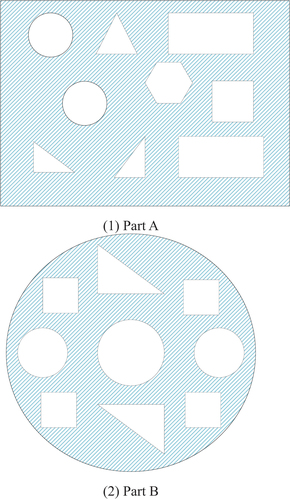
The section is composed of n closed curves (closed loops), and the contour path planning is to print the closed loops one by one. Each closed loop needs to determine a print starting point and an end point, and there are n starting points in the whole section. It is easy to see that the contour path planning problem can be reduced to the classical traveling salesman problem (TSP), which is essential to find an optimal path among n starting points so that each starting point is traversed only once, thus reducing the printing time of the part.
According to the characteristics of the fused deposition 3D printing process, when the part is sliced and layered, a single-layer cross-section of the part is obtained, in which the inner and outer contours are composed of multiple closed polygons, and the principle of determining the starting point of the polygon contour is to ensure that each polygon has only one starting point for printing and that the starting point of each polygon is the smallest distance between the principle of determining the starting point of the polygon profile is to ensure that each polygon has only one printing starting point and the distance between the starting points of each polygon is minimum. Assume that a layer section contains m polygons, i.e., where
is the outermost polygon profile. Each polygon profile is composed of n vertices, and the set of vertices of any polygon
.
If the set of starting points of a layer after 3D printing slices satisfy the minimum value of
, then the points in R are the starting points of the polygon contour. Then, the objective function to determine the starting point of the polygon profile can be expressed as:
where: is the print start point of the determined polygon profile.
denotes the distance from the starting point
to the starting point
of the polygon contour. The coordinates of
and
are
and
, respectively.
In this paper, a modified shortest distance method will be used to determine each polygon contour’s starting point. The specific steps are as follows:
Selecting the print origin
as the starting point, and setting
Then solve the distance from point
According to step (2), calculating the distance between the point
After selecting the set of starting points
Following the idea of step (4), update
For the last starting point
Optimization Algorithm for Path Planning of 3D Printed Slice Contours
Path Planning Model
The goal is to find an optimal print path that satisfies the requirements of fused deposition 3D printing so that each start point is reached only once, and the start point is also the end point of the printed polygon profile, which can reduce the air travel distance of the print head, shorten the part forming time and improve the printing efficiency while ensuring the print quality. From the set of starting points in the previous section, the points in R are the starting points of the polygon contour, and the 3D printing. The mathematical model for contour path planning of 3D printed slices can be expressed as:
where: denotes the distance from the start point Si of the polygon profile to the start point
of the polygon profile.
denotes the distance from the starting point Si to the starting point
of the polygon contour.
means the starting point
is removed from the set of starting points R.
In this paper, the polygon contour path optimization problem is transformed into a convex optimization problem by constructing a path selection function as the objective function, at which time the objective function is convex, and then the global iterative calculation is completed by HNN for optimal solution, so as to achieve the determination of optimal path planning.
HNN
HNN searching for paths will appear to fall into very small. Therefore, when describing the stability of the equilibrium point, we should introduce the energy function, which is used as the objective function, and the objective function is expressed as (Yu et al. Citation2022, Citation2022).
It can be proved that and the zero point corresponds to the minimal value point of the objective function
, which indicates that HNN always converges to the minimal point of the objective function (Lin et al. Citation2022).
Thus, after processing, it becomes a convex optimization problem with constraints (Sun, Sun, Sathasivam, and Khan Bin Majahar Ali Citation2022):
The Equationequations 4(4)
(4) and Equation5
(5)
(5) be the energy functions of a Hopfield neural network, which is a type of recurrent artificial neural network used for pattern recognition and optimization problems. The energy function is a measure of the state of the network, which is characterized by the binary activation values of its neurons.
The first term of the energy function represents the interaction between neurons in the network, where is the weight of the connection between neuron i and neuron j. This term is responsible for encoding the patterns that the network has learned to recognize, by adjusting the strengths of the connections between neurons based on the input patterns.
The second term of the energy function represents the external input to the network, where Ii is the external input to neuron i. This term is responsible for biasing the network toward certain patterns or states, by providing additional input to specific neurons.
The third term of the energy function represents the dynamics of the neurons, where is the time constant of neuron i and
is the inverse of the activation function of neuron i. This term is responsible for controlling the rate of change of the neurons, by adjusting the time constant and the activation function of each neuron.
Overall, the energy function of the Hopfield neural network captures the complex dynamics of the interactions between neurons in the network, as well as the external inputs and the dynamics of the neurons themselves.
The physical mechanisms underlying these interactions are complex and involve a combination of electrical and chemical processes, which have been extensively studied in the field of neuroscience.
The solution set with n points requires n(n −1) neural units, and each element in the adjacency matrix of the solution set corresponds to a nerve element except for the diagonal elements. The neurons take only two states, 0 or 1. When the network of HNN converges to a stable equilibrium state, the neuron state function can be expressed as (Huang et al. Citation2022):
The neuron state function is on the optimal path when the arc is 1, and
is 0 then it is not on the optimal path. The key step of the neural network solution is to set the parameter criteria, where the kinetic equation for the optimal path is obtained as:
where: is the weight among the nodes of the road network,
are the penalty coefficients. Solving the system of equations consisting of Equationequation (8)
(8)
(8) and Equationequation (9)
(9)
(9) , when the HNN converges to the stable equilibrium state, the output neuron is the required optimal path.
The flow of HNN to solve the optimal solution for 3D printing order is shown in .
Figure 2. The flow of HNN to solve the optimal solution for 3D printing order.
IWOA-HNN Based 3D Printing Contour Slicing Path Optimization Model
IWOA Based on Nonlinear Weight Update Method
Probabilistic Preference Selection Mechanism
WOA assumes that the probability of a group of whales choosing to surround and feed on a prey is 50%, and that the probability p generated by each iteration of the algorithm is a random number uniformly distributed between [0, 1] (Hsu and Wang Citation2023).
where p is a random number between [0, 1]. This is inconsistent with the actual nature animal hunting criterion, after the predator finds the prey in nature, the predator. The probability of prey encirclement and prey predation varies with time. The probabilities of prey encirclement and prey predation show corresponding changes with time, so the probabilities p generated in WOA does not obey a uniform distribution. We simulate the prey preference behavior of whale schools in order to improve the convergence accuracy and global exploration ability of WOA. To improve the convergence accuracy and global exploration ability of WOA, we simulate the prey preference behavior of whales, and set the probability generation method not to obey uniform distribution but to vary with the iteration In order to improve the convergence accuracy and global exploration ability of WOA, we set the probability p generation method not to obey uniform distribution but to change with the iteration process, i.e., the WOA iteration process is divided into two stages (Pham, Chon, and Kyung Ahn Citation2023).
Pre-iteration: simulate and speed up the process of searching and encircling prey by whales. In order to increase the probability of successful prey capture, IWOA assumes that in the first iteration of the algorithm, the school of whales mainly performs the task of searching and encircling prey. Only the first equation in Equationequation (10)
Late iteration: simulate and speed up the process of whale attack and prey capture. In order to improve the speed and probability of prey capture, it is assumed that in the late iteration the whales mainly perform the task of attacking and capturing prey. Only the second equation in Equationequation (10)
In summary, the updated probability generation formula is given as
where is the skewed distribution random number generation method, and tmax is the maximum number of iterations of the algorithm.
is the maximum number of iterations of the algorithm. From Equationequation (11)
(11)
(11) , we can see that the probability of generation is not between [0, 1], so the edge of boundary is bounded:
In the early iterations, the probability values generated by hunting preferences were mostly between 0 and 0.5. While in the late iterations, the probability values generated by hunting preferences were mostly between 0.5 and 1.0. The modified probability generation strategy not only increased the prey encirclement ability of the whale group in the early stage but also improved the prey predation ability of the whale group in the late stage.
Parameter Nonlinear Correction Strategy
In WOA, and
are the important parameters controlling whale school search, encirclement and prey. The value of
is determined by the convergence factor a. The convergence factor a showed a linear decreasing trend, indicating that the distance between whales and prey is linearly decreasing. The parameter
is in the range of [−2, 2] and converges to 0 with iterations, which simulates the hunting process of whale schools. The faster the parameter
converges, the faster the algorithm converges. The parameter
is a uniformly distributed random number between 0 and 2, which indicates that the distance between whales and prey varies randomly and has no significant effect on the global exploration and local exploitation of the algorithm. The parameter
is a random number with uniform distribution between 0 and 2, which indicates that the random change of distance between whales and prey has no significant effect on the global exploration and local exploitation of the algorithm. Therefore, to improve the convergence performance of WOA and the ability of local escape extremes, the parameters are modified. The modified convergence factors a and
are:
where: , α is the parameter controlling the decay of parameter a, β is the parameter controlling the rise of parameter a, t is the number of current iterations, and randn denotes a normally distributed random number generated.
The updated convergence factor a has a non-linear decreasing trend and converges faster, while the updated parameter converges faster, and the whale group can catch the prey faster when hunting, which means that the convergence speed of the algorithm is accelerated. The updated parameter
fluctuates randomly between [−4, 4], which increases the space for the whales to search for prey and improves the possibility of the algorithm to jump out of the local extremes. Overall, the updated parameters can significantly improve the global and local search ability of WOA relative to the original parameters.
Weight Position Update Strategy
In order to speed up the process of moving the whale group to the optimal whale individual and encircle the prey quickly, a nonlinear perturbation factor is introduced to enhance the algorithm’s global and local optimization finding ability.
where is the optimal solution position vector in the current whale population,
and
are coefficient vectors. a is a nonlinear perturbation factor. To correspond to the two stages of the probabilistic preference selection mechanism proposed in this paper, ω is defined as
where: ,
is the number of current iterations,
is the maximum number of iterations. From EquationEqs. (15)
(15)
(15) and (Equation16
(16)
(16) ), we can see that: in the iterative search process of the algorithm. The nonlinear perturbation factor ω has two functions: when
, it increases the ability of the algorithm to jump out of the local optimum. When
, the algorithm increases the search step size and thus makes the algorithm converge faster.
For common chaotic perturbation factors, the ability of the algorithm to escape the poles is enhanced by its chaotic nature. The chaotic nature of the algorithm enhances the ability of the algorithm to escape from the extremes, which makes the solution of the global higher probability of solving the global optimal solution, but also makes the algorithm converge slower. The proposed nonlinearly perturbed algorithm can be used to solve the global optimal solution. For the proposed nonlinear perturbation factor ω, it not only enhances the ability of the proposed nonlinear perturbation factor ω not only enhances the ability of the algorithm to escape local extrema but also speeds up the convergence of the algorithm by increasing the search step length.
The proposed nonlinear perturbation factor ω not only enhances the ability of the algorithm to escape local extrema but also accelerates the convergence speed by increasing the search step. Therefore, compared with the chaotic perturbation factor, the proposed nonlinear perturbation factor has better performance than the chaotic perturbation factor. In summary, the algorithm's position update equation is modified as
When , ω is calculated by Equationequation (17)
(17)
(17) , and when |
, the value of ω is 1.
is the distance between the optimal whale individual and other individuals.
Flow of IWOA-HNN
Encoding
To solve the optimization problem using IWOA, we first need to solve the encoding problem. Since the parameters of the HNN are optimized, we use the real number encoding approach in this paper, which means that we can directly represent an individual by a sequence of parameters. There are four parameters to be optimized, let Pt be the t-th generation of individuals, and the encoding is expressed as
At the time of individual initialization, according to the given range of values for each parameter, the generated random numbers of the given range separately to generate the first-generation population.
Fitness Function
The fitness function is a criterion to evaluate the goodness of an individual. When an individual is decomposed into parameters, it enters into the solution process of the HNN, and the final energy function value after the network reaches the steady state after several calculations is taken as the fitness function of this individual. The fitness function can be expressed as
is the energy value after a network optimization calculation with the parameters represented by this individual. Fitness takes a negative number to indicate that the lower the energy value, the greater the adaptation.
Flow of the Algorithm
The input of the algorithm is the search interval of each parameter, 3D printing model contour vertex coordinate value, population size, and iteration number; the output of the algorithm is the optimal parameter, the lowest energy function value, the optimal path, and the shortest distance. The algorithm is as follows:
Step 1: For the parameters to be optimized, set the respective search intervals according to previous experience, set the population size, randomly initialize the population, set the maximum number of iterations, and record the optimal individuals.
Step 2: Calculate the fitness value of each individual whale, which is the energy function value after network optimization calculation for the parameters represented by the individual.
Step 3: Update the position of each individual into the population based on probabilistic preference selection mechanism, parameter nonlinear correction strategy and weight position update strategy to check and correct the boundary.
Step 4: Re-solve the fitness values of all whale individuals to obtain the energy function values after the network optimization calculation and calculate the energy values after the network optimization.
Step 5: Select the fitness-optimal individuals from the population, save and judge whether the maximum number of iterations is reached, if so, the algorithm ends and outputs the fitness-optimal individuals and their corresponding parameters, the best route and the shortest distance, otherwise turn to step 2.
Experimental Analysis
In Fused Deposition Modeling (FDM) printing, the pattern used depends on the specific design of the 3D model being printed and the settings of the 3D printer. The FDM printing process involves the extrusion of a thermoplastic material, typically in the form of a filament, through a heated nozzle. The extruded material is then deposited layer by layer in a specific pattern to build up the 3D model. The most common patterns used in FDM printing include rectilinear, honeycomb, and triangular infills, which determine the internal structure of the printed model and affect its strength and weight.
The specific patterns used in FDM printing are typically chosen based on several factors, such as the intended application of the printed part, the desired strength, and durability, and the printing time and material usage. In general, denser infill patterns such as rectilinear provide greater strength and durability, while lighter patterns such as honeycomb reduce printing time and material usage. The choice of pattern can also affect the surface quality of the printed part, with some patterns producing a smoother finish than others.
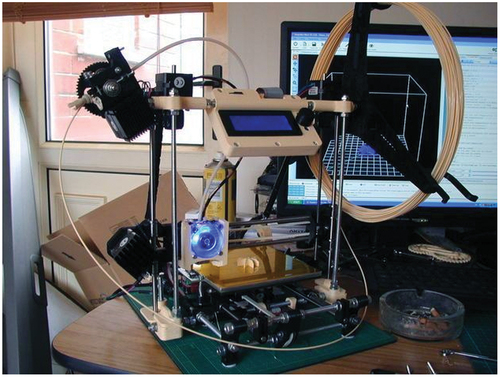
To verify the effectiveness and feasibility of the proposed sliced contour path optimization algorithm, the contour path planning process is performed for the parts in . The cross-sections of these two printed parts contain multiple complex polygonal contours ().
Figure 3. Fused Deposition 3D Printer.
First, the polygonal contours of the cross-sections are initially determined by the shortest distance method to obtain the set of polygonal contour starting points, and then the set of starting points is improved to obtain the optimized set of polygonal contour starting points. The polygon contour print start point data set is determined by the improved shortest distance method. The IWHO-HNN algorithm is applied to each point of the data set for path planning.
Figure 4. Comparison of printing time and contour length.
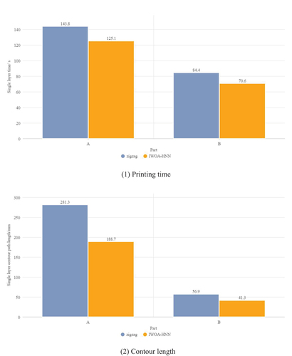
The part shown in was printed on a fused deposition 3D printer (with PLA material, 0.5 mm nozzle diameter, 0.2 mm slicing thickness, 60 mm/s printing speed and filling speed, and 120 mm/s air travel speed. The part was sliced by zigzag for contour path planning, and the proposed method was compared with it. The experimental results of comparison between two methods about printing time and contour length are shown in .
As can be seen from , the path planning algorithm proposed in this paper has reduced the printing time and contour path length compared with the traditional zigzag method. For part A, the part printing time has been shortened by 13% and the contour path length by 16.35% compared with the zigzag method. For part B, the part printing time has been shortened by 32.12% and the contour path length by 27.42% compared with the zigzag method. It can be seen that the printing efficiency of fused deposition 3D printed slices is significantly improved when IWOA-HNN proposed in this paper used.
Table 1. Comparison between two methods about printing time and contour length.
As can be seen from , the path planning algorithm proposed in this paper reduces both the printing time and the single-layer contour path length compared to the traditional zigzag method. In the application of IWOA-HNN, the printing time of part A is reduced by 18.7 s and the contour path length is reduced by 92.6 mm compared with the zigzag method, and the printing time of part B is reduced by 13.8 s and the contour path length is reduced by 15.6 mm compared with the zigzag method. It can be seen that the printing efficiency of IWOA-HNN proposed in this paper is significantly improved when fused deposition 3D printed slices are used.
For the dimensional accuracy of 3D printing, the IWOA-HNN algorithm proposed in this paper is compared with the traditional zigzag method to measure the standard dimensions of the printed parts by the two methods, as shown in .
Figure 5. Size accuracy comparison.
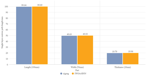
As can be seen from , the deviations of the length, width, and height of the part printed by this method are 0.11 mm, 0.07 mm, and 0.04 mm, respectively. The deviations of the length, width, and height of the part printed by the conventional zigzag method are 0.36 mm, 0.37 mm, and 0.21 mm, respectively, which shows that the dimensional accuracy of the part printed by this method has been improved.
The use of FDM printing has several industrial applications, due to its ability to produce complex geometries and functional parts with a wide range of materials. Here are a few examples:
Prototyping: FDM printing is widely used in the manufacturing industry for rapid prototyping, which allows designers and engineers to quickly test and iterate designs before mass production. This can help to reduce development time and costs, as well as improve the quality and performance of the final product.
Tooling: FDM printing can also be used to produce custom tooling, such as jigs, fixtures, and molds, which are used in various manufacturing processes. This can help to improve the accuracy and efficiency of the production process, as well as reduce lead times and costs.
Aerospace and Automotive: FDM printing is increasingly being used in the aerospace and automotive industries to produce lightweight and complex parts with high strength-to-weight ratios. This can help to improve fuel efficiency and reduce the overall weight of the vehicles while maintaining the necessary strength and durability.
Medical: FDM printing is used in the medical industry for the production of customized implants, prosthetics, and surgical tools. This can help improve patient outcomes and reduce the cost of health care as well as provide a more personalized approach to medical treatment.
Education: FDM printing is also used in education and research to teach students about additive manufacturing and to conduct experiments and studies on the properties and performance of various materials and geometries.
Overall, the industrial applications of FDM printing are diverse and continually expanding, driven by the ability of this technology to produce complex parts with high accuracy, speed, and customization.
Conclusion
In this paper, we propose an IWOA-HNN-based fused deposition 3D printing slicing contour path optimization control method. The method first explores the selection of the path starting point and determines the path starting point. Then, the HNN is used as the basic fused deposition 3D printing slice contour path optimization model, and IWOA is used to optimize the parameters of the HNN for its slow convergence speed and easy to fall into local optimum problem. Finally, based on IWOA-HNN, the path planning of the print start point is carried out to find the optimal printing sequence, which improves the efficiency of 3D printing and shortens the molding time. The results show that the proposed IWOA-HNN algorithm takes less time to print, has a shorter path, and has less error than the traditional path planning algorithm in the slicing software zigazag, which improves the printing efficiency and verifies the feasibility and effectiveness of the proposed method, and contributes to the further development of 3D printing technology.
Disclosure statement
No potential conflict of interest was reported by the authors.
Additional information
Funding
References
- Fok, K.-Y., N. Ganganath, C.-T. Cheng, H. Ho-Ching Iu, and K. Tse Chi. 2019. A nozzle path planner for 3-D printing applications. IEEE Transactions on Industrial Informatics 16 (10):6313–1716. doi:10.1109/TII.2019.2962241.
- Hsu, H.-P., and C.-N. Wang. 2023. Hybridizing whale optimization algorithm with particle swarm optimization for scheduling a dual-command storage/retrieval machine. IEEE Access 11:21264–82. doi:10.1109/ACCESS.2023.3246518.
- Huang, L.-L., Y. Zhang, J.-H. Xiang, and J. Liu. 2022. Extreme multistability in a Hopfield neural network based on two biological neuronal systems. IEEE Transactions on Circuits & Systems II: Express Briefs 69 (11):4568–72. doi:10.1109/TCSII.2022.3183340.
- Kim, D. H., and T. I. Zohdi. 2022. Tool path optimization of selective laser sintering processes using deep learning. Computational Mechanics 69 (1):383–401. doi:10.1007/s00466-021-02079-1.
- Lin, H., C. Wang, Y. Sun, and T. Wang. 2022. Generating-scroll chaotic attractors from a memristor-based magnetized hopfield neural network. IEEE Transactions on Circuits & Systems II: Express Briefs 70 (1):311–15. doi:10.1109/TCSII.2022.3212394.
- Liu, R., Z. Liang, Z. Wang, and L. Wei. 2023. Indoor visible light positioning based on improved whale optimization method with min-max algorithm. IEEE Transactions on Instrumentation and Measurement 72:1–10. doi:10.1109/TIM.2023.3240212.
- Liu, H., R. Liu, Z. Liu, and X. Shuhao. 2021. Minimizing the number of transitions of 3d printing nozzles using a traveling-salesman-problem optimization model. International Journal of Precision Engineering and Manufacturing 22 (9):1617–37. doi:10.1007/s12541-021-00512-2.
- Liu, D., S. Zhou, R. Shen, and X. Luo. 2023. Color image edge detection method based on the improved whale optimization algorithm. IEEE Access 11:5981–89. doi:10.1109/ACCESS.2023.3236761.
- Lomakin, K., S. Herold, L. Ringel, J. Ringel, D. Simon, M. Sippel, A. Sion, M. Vossiek, K. Helmreich, and G. Gold. 2019. SLA-printed 3-D waveguide paths for E-band using electroless silver plating. IEEE Transactions on Components, Packaging, and Manufacturing Technology 9 (12):2476–81. doi:10.1109/TCPMT.2019.2927671.
- Luo, R. C., L. Chuan Hsu, T. Jung Hsiao, and Y. Wen Perng. 2020. 3D digital manufacturing via synchronous 5-Axes printing for strengthening printing parts. IEEE Access 8:126083–91. doi:10.1109/ACCESS.2020.3007772.
- Ma, Z., W. Wan, L. Song, C. Liu, H. Liu, and W. Yiwen. 2022. an approach of path optimization algorithm for 3D concrete printing based on graph theory. Applied Sciences 12 (22):11315. doi:10.3390/app122211315.
- Meiabadi, M. S., M. Moradi, M. Karamimoghadam, S. Ardabili, M. Bodaghi, M. Shokri, and A. H. Mosavi. 2021. Modeling the producibility of 3D printing in polylactic acid using artificial neural networks and fused filament fabrication. Polymers 13 (19):3219.
- Moradi, M., R. Beygi, Y. Mohd, N. Amiri, A. da Silva, and S. Sharif. 2023. 3D printing of acrylonitrile butadiene styrene by fused deposition modeling: Artificial neural network and response surface method analyses. Journal of Materials Engineering and Performance 32 (4):2016–28.
- Pham, V. H., B. H. Chon, and H. Kyung Ahn. 2023. Whale optimization algorithm-based parallel computing for accelerating misalignment estimation of reflective Fourier ptychography microscopy. IEEE Photonics Journal 15 (1):1–9. doi:10.1109/JPHOT.2023.3241276.
- Sun, J., S. Sathasivam, and M. Khan Bin Majahar Ali. 2022. Analysis and optimization of network properties for bionic topology hopfield neural network using gaussian-distributed small-world rewiring method. IEEE Access 10:95369–89. doi:10.1109/ACCESS.2022.3204821.
- Sun, Y., W. Tian, T. Zhang, P. Chen, and L. Mujun. 2020. Strength and toughness enhancement in 3d printing via bioinspired tool path. Materials & Design 185:108239. doi:10.1016/j.matdes.2019.108239.
- Wang, T., L. Nanya, G. Link, J. Jelonnek, J. Fleischer, J. Dittus, and D. Kupzik. 2021. Load-dependent path planning method for 3D printing of continuous fiber reinforced plastics. Composites, Part A, Applied Science and Manufacturing 140:106181.
- Yu, F., X. Kong, A. Abdullah Mohammed Mokbel, W. Yao, and S. Cai. 2022. Complex dynamics, hardware implementation and image encryption application of multiscroll memeristive hopfield neural network with a novel local active memeristor. IEEE Transactions on Circuits & Systems II: Express Briefs 70 (1):326–30. doi:10.1109/TCSII.2022.3218468.
- Yu, F., H. Shen, Y. Qiulin, X. Kong, P. Kumar Sharma, and S. Cai. 2022. Privacy protection of medical data based on multi-scroll memristive hopfield neural network. IEEE Transactions on Network Science and Engineering 10 (2):845- 858.
- Záda, V., and K. Belda. 2022. Structure design and solution of kinematics of robot manipulator for 3D concrete printing. IEEE Transactions on Automation Science and Engineering 19 (4):3723–34. doi:10.1109/TASE.2021.3133138.