
 ?Mathematical formulae have been encoded as MathML and are displayed in this HTML version using MathJax in order to improve their display. Uncheck the box to turn MathJax off. This feature requires Javascript. Click on a formula to zoom.
ABSTRACT
Title blocks are crucial primary data on drawings necessary for the operation of modern manufacturing enterprises. However, their uniform export poses a challenge due to the heterogeneity across multiple sources and the variety of export templates. Therefore, this paper proposes an intelligent extraction method for title block information (TBI) based on fuzzy matching. This method evaluates the geometrical composition of the title block, the logical relationship between information cells, and the diversification of the title block. It establishes a weighted intersection point matrix for the title block as the topological structure model. The fuzzy matching, based on the intersection matrix points, disregards the variations in the size and position of the title block and focuses only on the style that impacts the extraction of information. The matched title blocks are categorized, and the base table of each type determines the information distribution of the title block. A hash table is then created between the description cell and the value cell of information to accumulate the TBI. The method is integrated into the AutoCAD software and presented with an interactive program interface. Finally, an example is presented to further demonstrate the stability, reliability, and efficiency of the method and the system.
Introduction
Engineering drawings created using software like AutoCADⓇ, NXⓇ, and CATIAⓇ, encompass the geometrical details, dimensions, tolerances, and manufacturing specifics of a part, as well as ancillary information such as part number, name, and material in the title block (Haralick and Queeney Citation1982). These details serve as a fundamental reference for part processing, assembly, manufacturing, and inspection (Su et al. Citation2017). Each engineering drawing corresponds to a specific part, with a single part being associated with a drawing frame. In the context of complex mechanical equipment, multiple parts correspond to numerous frames, typically compiled in a document such as an AutoCAD DWG file. Extraction and application of the data information from the drawing title block is essential for efficient part management. However, the absence of a unified standard for the title block, coupled with the substantial diversity in export information templates across enterprises, presents significant challenges in achieving generalization. Manual extraction of title block information (TBI) from CAD files, on a drawing-by-drawing basis, is exceedingly time-consuming, laborious, and prone to errors. Therefore, research into the intelligent extraction of drawing TBI holds immense engineering practical significance (Lee, Hyun Kim, and Lee Citation2012).
The 2D engineering drawing consists of geometrical and non-geometrical information (Amran et al. Citation2011; Çıçek and Gülesın Citation2004;Jabal et al. Citation2009). The non-geometrical information in engineering drawings includes parts list or bill of materials (BOM) extraction and TBI extraction (Amran et al. Citation2012; Sutisna and Setyanto Citation2021). In accordance with ISO standards, the title block is typically situated in the bottom right-hand corner of the drawing frame (although there are instances where it may be positioned in the upper right-hand corner or elsewhere, which are excluded from the scope of this paper’s discussion). This section is vital as it contains key information, and its orientation coincides with that of the frame. The BOM is specific to the assembly drawing and resides above the title block (Kwon Citation2006). Two primary approaches for extracting drawing information are modular and free table formats. The modular approach defines attributes for a specific BOM or TBI, ensuring targeted matching recognition, leading to high extraction efficiency and low error rates. However, its limitations arise from being specific to particular BOMs or TBIs. On the other hand, the free table format overcomes these limitations by utilizing the virtual table method to interpret text information of drawings, facilitating broader applications, and handling TBIs in different formats. Nevertheless, it requires further improvements for extremely irregular title blocks, necessitating extensive research efforts (Ab. Jabal et al. Citation2009; Amran, Sulaiman, Kahar, et al. Citation2012; Deepika and Haran Citation2013; Li et al. Citation2013; Sulaiman, Mohd, and Nur Citation2012). Shih (Citation2014) enabled sharing of product data information in the manufacturing environment by converting structured product BOM into an Excel file format. Matías et al. (Citation2008) introduced an automated BOM generation method based on variant specifications and attribute patterns. Jiang et al. (Citation2010) proposed a collection method for obtaining text objects and their location information, developing the automated generation of BOM, standard, and purchase bills. Yang and Ping Hai (Citation2014) conducted a secondary development of AutoCAD software to facilitate TBI transmission between AutoCAD and PDM. Moreover, Amran et al. (Citation2018) investigated entity filtering technology to enhance non-geometrical information extraction. Given the intimate link between non-geometrical information in engineering drawings and part manufacturing, model management, design, and data maintenance, the accuracy of its extraction is of paramount importance (Liang and Gang Wei Citation2012; Tao and Yin Citation2013, Çıçek and Gülesın Citation2004).
The extraction of non-geometrical information entails extensive data search, recognition, and filtering. Given the varied types of information and the lack of unified distribution rules, efficient methods, such as fuzzy matching, are essential (Chen et al. Citation2014; D’Aniello et al. Citation2021; Li, Long, and Zhou Citation2019; Serrano-Guerrero, Romero, and Olivas Citation2021). Fuzzy matching is widely utilized in information extraction (Bhasuran et al. Citation2016; Sehgal and Crampton Citation2019; Zheng et al. Citation2016). Guo et al. (Citation2020) introduced a 2D free-form layout method based on geometrical similarity feature search and fuzzy matching, applicable to any 2D free-form layout. Similarly, Pikies and Ali (Citation2021) integrated the fuzzy string-matching algorithm with a second layer convolutional neural network (CNN) binary classifier for automated ticket classification and processing. Li, Yan, and Ma (Citation2019) utilized a fuzzy graph to model resource description framework data, enabling query equivalence for subgraph searches. Despite its widespread use, the performance of fuzzy matching is significantly influenced by its construction and fuzzy rule base. Fan et al. (Citation2020) addressed this by proposing a multi-layer fuzzy model with modified fuzzy rules to enhance the system’s approximation ability. In graphic documents, substantial information lacks matching relationships and falls under the elements of the document (Rica et al. Citation2020). Effective and accurate extractions of the required information necessitates matching all drawing details in each frame (Bryan Citation2020), requiring comprehensive searches within the frame to match information within the title block. Thus, employing the fuzzy matching algorithm can significantly enhance the search efficiency.
In summary, this paper introduces an intelligent method for extracting multi-source and heterogeneous TBI based on fuzzy matching. This involves investigating the spatial position of the title block within the drawing frame to establish its correspondence with the TBI. Subsequently, the TBI obtained through fuzzy matching is exported to the corresponding multi-style template file. Finally, it is seamlessly integrated into AutoCAD software, forming a rapid and intelligent extraction system for multi-source and heterogeneous TBI, with an interactive and visual program interface. As a result, this research offers a significant contribution to the generalization of the extraction of non-geometrical information from engineering drawings, and it enhances the network and information management of such documents.
Structure Analysis of Title Block
Information Composition of Title Block
The title block of the drawing contains essential description and management information, encompassing attribute details of each part code (such as drawing number, standard part number), name, quantity, and material, along with their relationship. This information is crucial in both assembly and part drawing. The title blocks in engineering drawings are predominantly depicted as tables, illustrated in . These are two-dimensional (2D) tables filled with text, housing a wealth of information during the product design process. The fundamental components of the table are line segments and strings, both of which are presented in graphical form. The line segment set that forms the table’s boundary comprises geometrical attributes, including position, size, and coordinates, representing the graphic data in the drawing. The text data within the string forms the main content of TBI and drawing management information, and its extraction is fundamental to the development of engineering drawing document systems.
Figure 1. Title block table.
The title block table comprises mainly of vertical and horizontal line segments, which divide the table area into multiple rectangular cells. These line segments, along with the string (including empty string), collectively form a table cell. The line segments serve as the boundaries of the cell, while the string constitutes the cell’s content. The position of the string within the cell is flexible, but it remains within the boundary range, establishing a containment relationship. Consequently, the cell is considered the primary unit of the TBI table, which is an ordered set of cells. A cell is a compound entity, characterized by both geometrical and textual attributes, expressed through boundary line segments and inclusive strings. The textual attribute not only forms the core of the cell but is also the focus of extraction and recognition.
In order to elucidate the relationship between line segments and the composition of cells in the title block, a line segment numbering system is utilized. The line segments in the TBI table are categorized into two groups: horizontal line segment group HL and vertical line segment group VL. The coordinates (starting point),
(midpoint), and
(ending point) of the straight-line segments are known. A line is classified as vertical when denoted by
and as horizontal when denoted by. Once segmented, the vertical line groups are arranged in ascending order based on their X coordinates, with a secondary arrangement by the Y coordinates in case of identical X coordinates. Conversely, the horizontal line groups are arranged in descending order according to the Y coordinates, with a secondary arrangement in ascending order by the X coordinate in case of identical Y coordinates. Both horizontal and vertical lines in the table are numbered independently, as shown in , ensuring that each cell in the information table is delineated by a unique boundary line number
. As displayed in , the unique numbers
and
represent the count of horizontal lines, where
, and m denote the number of horizontal lines, while
and
signify the count of vertical lines, with
, and n representing the number of vertical lines. The cell expression is denoted by
, with str representing the text data in the cell string. Hence, the cell expression for the “Key_1” string in is
.
Figure 2. Table cell.

Logical Relationship Between Table Cells
The relationship between table cells in general tables can be segmented into semantic and positional relationships. Semantic relations categorize table cells into two types: description cells, denoted by “Key,” used to label and identify the type and name of title bar information; and value cells, denoted by “Val,” representing the specific content related to the information type described by the description cells. The “Key-Val” relationship between description and value cells forms a cell group, enabling the expression of specific aspects of TBI content. These cell groups can be classified into two types: one comprises both description and value cells, while the other is solely composed of value cells, with the description cells being implicit. As illustrated in , the description cell “Key_5” is implicit in the “Val_5” cell group. In this context, the keyword of such table cells can be considered as the associated information value.
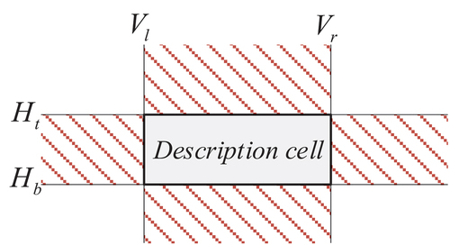
The representation of cell groups conveying the same type of information on a table is not uniform. Based on the description cell, there are approximately four scenarios wherein the value cell appears. As displayed in , the shaded area denotes where the value cell may emerge. Within the table, there exists a cell Group (cell 1, cell 2), with cell 1 being labeled and cell 2 being labeled
. When
and
are involved, it signifies that cell 1 and cell 2 are within the same row. Furthermore, when
is the case, it indicates that cell 2 is positioned to the right of cell 1. Conversely, when
is used, it denotes that cell 2 is on the left side of cell 1. Similarly, when
and
are applied, it means that cell 1 and cell 2 are situated within the same column. If
is indicated, it signifies that cell 2 is positioned above cell 1. Conversely, when
is utilized, it communicates that cell 2 is situated below cell 1. If the positional relationship of the cell group is denoted by
, the expression of the cell group is derived as Group (cell 1, cell 2, Pr).
Figure 3. Positional relationship of cell group.
Diversity of Title Blocks
The challenge in extracting the TBI from a drawing lies in the variability of the TBI table, which encompasses differences in location, size, and style. Typically, the title block may be positioned at any of the four corners of the drawing frame, with each corner holding a variable placement for the title block. Consequently, given the variability in the position of the four corners and the viewing direction of the title block, there are potentially 16 different orientations for the title block. illustrates the possible corner position of the title block, with “A” denoting the viewing direction.
Figure 4. Possible locations of title block on a given corner of the drawing.
Size diversity entails two aspects. Firstly, the global size of the title block varies with the dimensions of the drawing. Secondly, the composition of the drawing title block includes numerous rectangular table cells, leading to increased complexity in the template base table due to its size variations. As shown in , both title block #1 and title block #2 have an equal number of horizontal and vertical line segments, as well as identical orders of the four-line segments constituting independent cells. The cells exhibit identical positional relationships and topologies, indicating the similarity between the two tables. Furthermore, the distribution of information within title block #1 and title block #2 is also identical. However, adopting the conventional “modular attribute text” method requires pre-defined frame structure and text attributes in the template, resulting in template redundancy and reduced efficiency in drawing matching and information extraction.
Figure 5. Similarity of title blocks: (a) title block #1, (b) title block #2.
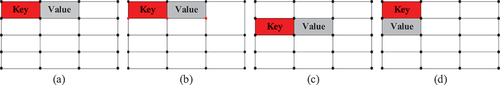
The diversity of table styles is a key feature that best reflects the diversity of title blocks, and it encompasses several aspects. Firstly, the variability lies in the number of table cells, leading to a diverse number of intersection points in table segments. Comparing the number of intersection points in two tables allows for the identification of the similarity in the number of table cells. Additionally, as shown in , there is a clear distinction between description cells and value cells in the table, and a specific positional relationship exists between them. Specifically, each description cell and its corresponding value cell form a group. Therefore, it is crucial to consider the information provided by the description cell in order to distinguish between the two tables. Furthermore, even when the location of the description cell is the same, if the location of the corresponding value cell differs, it can indicate that they are part of two different tables.
Figure 6. Similarity of title blocks: (a) base table, (b) different number of intersections, (c) location of description cell is different, (d) the relative positions of the cell group are different.
Title Block Intersection Point Matrix Fuzzy Matching
Intersection Analysis of Line Segments
The identification of intersection points between line segments is a common mathematical problem, typically approached in two steps. The first step involves determining whether an intersection point exists between two line segments. Subsequently, if an intersection point is confirmed, the second step is to calculate the coordinates of this point. In Section 2.1, the line segment of the TBI table is categorized into two groups: horizontal line segment group (HL) and vertical line segment group (VL), with each group organized according to specific rules. This study utilizes the endpoint coordinate comparison method to assess the potential existence of an intersection point between the two line segments. It states that if horizontal line and vertical line
satisfy the conditions specified in Eq. (1), an intersection point between them is guaranteed, and the coordinates of the intersection point can be computed. Specifically, the abscissa of the intersection point aligns with that of the horizontal line, and the ordinate corresponds to the vertical line. The resulting intersection coordinates are denoted as (a, b), yielding the coordinates of the intersection point as
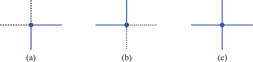
. By comparing the endpoint coordinates of the two line segments, the intersection points can be categorized into nine types, as demonstrated in .
Figure 7. Nine cases of intersection of two-line segments.
When only the upper left corner and lower right corner of the cell are available, the enveloping boundary of the cell can be detected. The evaluation in illustrates that the intersection points with type number ①, ②, ④, ⑤ can serve as the upper left corner, and the intersection points with type number ⑤, ⑥, ⑧ ⑨ can be utilized as the lower right corner. Therefore, nine intersection point types suitable for the upper left corner or lower right corner are retained and defined as construction points, while other types are eliminated. As explained in , three types of construction points can be derived; represents the intersection points with type number ①, ② and ④, depicts the intersection point with type number, and, and signifies the intersection point with type number ⑤.
Figure 8. Types of construction points.
Establishment of Weighted Intersection Point Matrix
This paper introduces the concept of an intersection point matrix, denoted as , that depicts the relative spatial relationship between the line segments within the title block of engineering drawings. Each matrix element is assigned a value of either 1 or 0. The construction principle is articulated as follows: when the ith line segment in the horizontal line segment group (HL) intersects with the jth line segment in the vertical line segment group (VL), it is labeled as
, otherwise, it is designated as
,
. The horizontal line segment group (HL) comprises m line segments with varying Y coordinates of endpoints, while the vertical line segment group (VL) consists of n line segments with different X coordinates of endpoints, as shown in Eq. (2).
The matrices of the intersection points of the two tables featured in are identical. However, it is evident that they possess different table styles due to the presence of merged cells. Consequently, it is not feasible to exclusively establish a title block table structure simply by utilizing the intersection point matrix. Therefore, an intersection point type matrix is introduced to refine the original intersection point matrix, and the resulting weighted modified intersection point matrix is utilized as a measure of similarity. Here, denotes the intersection point type in row i and column j. Subsequently, based on the analysis from Section 3.1, an intersection-type matrix is formulated as shown in Eq. (3). The resultant modified weighted intersection point matrix is presented in Eq. (4). Consequently, the title block table can be distinctly represented by the weighted intersection matrix, WMC. The two tables depicted in can be differentiated by two distinct weighted intersection point matrices. Let the intersection point matrices corresponding to be denoted A and B, respectively. Prior to weighting, A[3][2]=B[3][2] = 1, A[3][3]=B[3][3] = 1, and both elements are equal to 1, indicating the presence of an intersection point at these positions, but the intersection point type cannot be discerned. After correction by the MT matrix, A[3][2]=-1, A[3][3] = 1, B[3][2]=B[3][3] = 4. As a result, the matrix structure is inferred from the positioning of the matrix elements. illustrates the weighted intersection point matrix obtained by combining and weighting in .
Figure 9. Representation of intersection point matrix:(a) , (b) , (c) intersection point matrix.
Figure 10. Representation of weighted intersection point matrix:(a) , (b) , (c) weighted intersection point matrix of , (d) weighted intersection point matrix of .
Table 1. Details of five types of title blocks.
Table 2. Information statistics of each type of title block.
Fuzzy Matching Method Based on Intersection Point Matrix
The weighted intersection point matrix can uniquely represent the TBI table of a drawing, and the distinct matrices reflect the diversity of table styles. However, an accurate matching method necessitates complete uniformity in table position, size, and style, which has many drawbacks and low practical compatibility. Hence, this paper proposes a fuzzy matching algorithm based on the weighted intersection point matrix, which disregards differences in size and position of the drawing TBI table, and solely considers the table style affecting the TBI extraction. Subsequently, the post-fuzzy-matched tables will be classified into multiple types, permitting rapid extraction and storage of the TBI for all drawing types based on the table information of each type. When comparing two weighted intersection point matrices with varying meanings and sizes, we separately examine each of their element’s results in inefficient operations. As a solution, this paper introduces the concept of matrix norm, which encompasses the definitions outlined below.
We assume that V is a linear space over the number field P, and is a non-negative real-valued function with vector α in V as its independent variable. If it satisfies the following three conditions, then
is termed the norm of vector α, and the linear space defining the norm is referred to as a bound norm linear space. The three conditions are:
Nonnegativity: When α≠0,
>0; when α = 0,
Homogeneity: For any k∈P and α∈V,
Triangle inequality: For any α, β∈V,
The essence of the norm definition is to obtain a measure of the “size” of a vector in a linear space or a comparison of the “proximity” between two vectors. Common norms include the L1 norm, L2 norm, and infinity norm (maximum norm). This paper utilizes the L2 norm, also known as the Euclidean norm, which is frequently used. Its equation expresses the Euclidean distance from the origin to the point determined by vector X. The L2 norm of the matrix is also referred to as the Frobenius norm, as described in Eq. (5). The difference between matrix A and matrix B is determined by calculating the norm, as shown in Eq. (6). If = 0 according to the norm definition, it implies that the two matrices are equal. This equivalence indicates that the table structure corresponding to the two weighted intersection point matrices is identical, allowing them to be categorized as the same type of table. Therefore, the TBI can be extracted using the same extraction rules.
TBI Extraction and Export
Definition of Base Table
Many of the drawings are categorized and classified into different types, enabling efficient management and the rapid creation of a base table for information extraction. The base table, an empty table denoting the same type with no specific content, distinguishes itself from the specific TBI table by having all value cells’ text attributes are empty strings. Each table has its own unique base table, facilitating quick identification of different table types through a dedicated base table library. By utilizing cell identification, the type cells and value cells are differentiated and organized into cell groups. Taking as examples, the specific steps for defining the base table are as follows:
Extraction and Export of Information
Hash technology is employed to store records in a contiguous storage space. A specific corresponding function f is defined between the storage location of records and their keywords, such that each keyword is associated with a storage location f(key), known as the hash function. During a search, the mapping f(key) of the given value key is located based on the established correspondence. If this record exists in the search set, it will be found at the position of f(key). Given that the TBI represents typical key-value pair data, this paper utilizes a hash table for the storage and management of the associated data information.
The extraction of the TBI involves retrieving the string information from the cell group associated with the title block. The content within the title block is obtained from the linked list of cell group information, as outlined in Section 4.1. This list comprises base table cell group data denoted as Gs (cell 1, cell 2, Ig), where,
,
, n represent the extracted data. Utilizing the string “str” from cell 1 as the key, the location of the title block’s description cell to be extracted is determined through the line segments number
of the cell 2 value cell, namely, line segments
and
in the horizontal line segment group, and line segments
and
in the vertical line segment group of the title block. Subsequently, the intersection points of line segments
and
(upper left corner
) and the intersection points of line segments
and
(lower right corner
) are calculated. Assuming the positioning coordinates of the corresponding value cell string as
, it follows the principle that the cell boundary contains the string represented by
and
. Finally, the extracted string information is stored as a key-value pair in the hash table corresponding to the title block table data. Similarly, this process can be applied to extract all the information within the title block of a drawing.
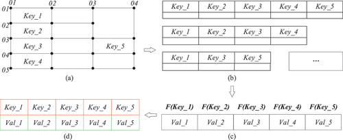
Upon completion of the information extraction process, the extracted data need to be exported to generate the corresponding Excel table. As depicted in , the defined base table encompasses all the data types intended for export from this drawing category. In the case of multiple export templates, the information and format for export vary significantly. Leveraging the standardized extraction and storage of TBI detailed earlier, the relevant values in the hash table can be accessed using the template’s keyword information and subsequently written row by row into the Excel table. This facilitates the realization of multi-style export templates and establishes a reference standard for efficiently and accurately exporting TBI.
Figure 11. Export method of TBI: (a) definition of base table, (b) multi-export-style template, (c) hash table, (d) export table of TBI.
Systematic Development
System Architecture
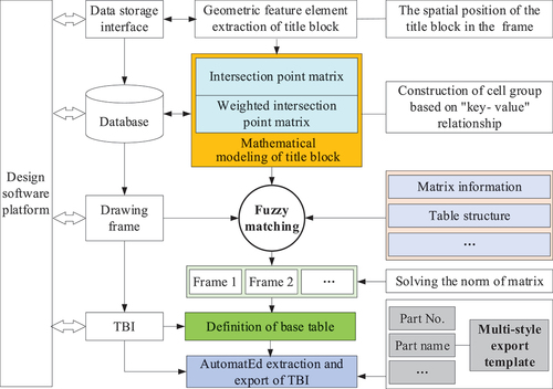
illustrates the architecture of the system developed in this paper, which can be seamlessly integrated into various CAD software platforms, such as AutoCAD, NX, Creo, and SolidWorks. However, in this study, this method is specifically integrated into AutoCAD software due to its widespread application across various fields including civil architecture, decoration, industrial drawing, engineering drawing, electronic industry, and garment processing. The method involves several key steps. Firstly, it identifies the geometrical feature elements of the title block to obtain the spatial position of the title block within the frame. This step is crucial for assessing the drawing type and serves as an important input parameter for drawing fuzzy matching. Secondly, it constructs a matrix mathematical model of the title block, and derives its intersection point matrix and weighted intersection point matrix as unique representations to discriminate different title block tables. It also establishes the “key-value” relationship of the cell groups, which is then stored in the database. Thirdly, the weighted intersection matrix of the drawing is used for fuzzy matching to initially classify the title block, followed by achieving accurate classification through the calculation of the norm of the matrix. Finally, by defining the base table, it establishes the hash table of the data corresponding to the title block table, allowing for the rapid and accurate exports of the TBI to the multi-style template file.
Figure 12. System architecture.
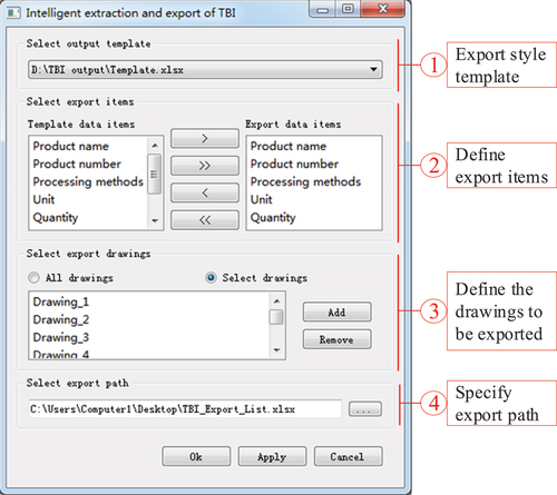
The system presented in features an interactive dialog box, comprising four main components. Firstly, users are prompted to select an export template, allowing them to pre-specify paths of multi-style export template files and choose from a drop-down menu. The system then displays the export data items of the template in the order they are contained, enabling users to determine the data items for extraction. These preparatory operations are essential before information extraction. The subsequent step involves identifying the drawings’ TBI that need to be exported, offering two options: “all exports” or “selecting exports.” The former exports the TBI of all drawings in the current DWG file, while the latter requires users to select specific drawings in AutoCAD for export. Finally, users are required to define the name and storage path of the TBI export file. The system allows for the customization of various parameters and their selections as default values. Utilizing an MFC design dialog box based on ObjectARX, the system ensures a visually appealing and user-friendly interface with intuitive input conditions, making the operation process simple and convenient. This design enables users to efficiently complete the extraction and export of TBI through user-friendly prompts.
Figure 13. Interactive dialog box of the system.
Fuzzy Matching and Accurate Export
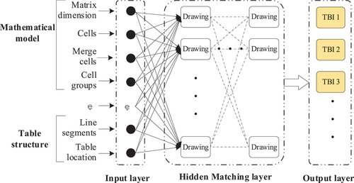
The theory of fuzzy systems is not only scientific but also forward-looking and practical, providing valuable guidance for this project. By analyzing the mathematical model of the drawing node and the title block area, the internal relationship between the TBI of the drawing, the frame, and the title block area is thoroughly examined. Furthermore, the functional connection between the TBI and the mathematical expression model is established to create the fuzzy matching system between the multi-source TBI and the multi-style export template, as illustrated in . The input parameters of fuzzy matching encompass the structure of the title block and the relevant information of its weighted intersection point matrix. This information is then utilized to conduct fuzzy matching for the title blocks of all drawings, resulting in their classification. While this classification may be coarse, it significantly enhances search efficiency and enables immediate identification of their types, thereby providing robust support for the accurate extraction of information during subsequent export of multi-style templates.
Figure 14. Fuzzy matching of multi-source TBI.
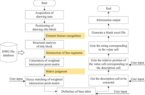
The preliminary classification of drawings and their title blocks is achieved through fuzzy matching. To accurately match the title blocks of the drawing, the norms of the matrix are further compared to finalize the classification of the title blocks. Subsequently, by defining the base table for each type of title block, the text information of the description cell and the location of the corresponding value cell are exported based on the demand to export template data items. Presented in , the flowchart of the system mainly divides the extraction of engineering drawing TBI into two steps: extracting the required string in the drawing title block and exporting the extracted string information to write it into an Excel template table, generating a TBI file. These steps correspond to the left and right columns of , respectively. The complexity of extracting drawing table strings lies in the diversity of drawings and tables, rendering traditional attribute definition methods inefficient in obtaining the required information. Hence, drawing and table classification is necessary to reduce the need for customized export information and the filtering of graphic elements, thus promoting export efficiency. Initially, the system reads the DWG file database, retrieves the drawing areas, and generates a linked list of drawing areas. For the selected drawings, determining the spatial position and structure of their frames and title blocks is essential. This is followed by the evaluation of their spatial structure and composition, and the calculation of their intersection point matrix and weighted intersection point matrix. Subsequently, fuzzy matching is carried out based on the weighted intersection point matrix, and the TBI is extracted step by step in correspondence with the process and exported to the template file. The subsequent processes have been detailed in earlier sections, and the specific process will not be reiterated here. Notably, there are four processing steps that require user input parameters to ensure accurate export.
Figure 15. System flowchart.
Examples and Discussions
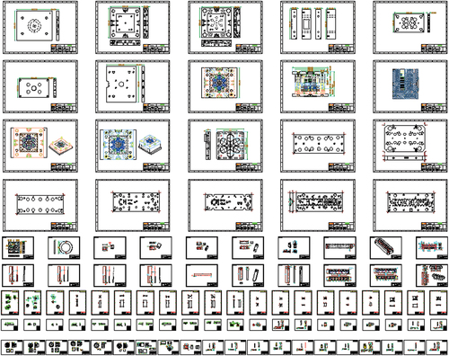
This section demonstrates the extraction of TBI from a drawing file using the proposed method and system. depicts the drawing model within the DWG file, comprising a total of 100 drawings with varying frame sizes and distinct title block compositions. Manually selecting and extracting information from the frame is arduous and error-prone when dealing with numerous title block drawings, each with diverse characteristics. However, employing the proposed method and system provides significant advantages. Notably, the common feature among these drawings is the spatial positioning of their title blocks in the lower right corner of the frame. Therefore, by identifying this position, the geometrical elements of the title block structure, consisting of interconnected straight lines within or outside the frame boundary, can be rapidly retrieved. It is evident that the title block area, composed of these lines, exhibits diverse characteristics and multi-source heterogeneity. Subsequently, leveraging the proposed method and system, the extraction of TBI and the export process of multi-style templates are presented in detail.
Figure 16. Examples of engineering drawings.
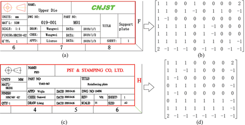
First, the intersection point matrix and the weighted intersection point matrix were constructed for all drawing title blocks. depicts the matrices of two title blocks. Despite both presenting as a 5-row by 7-column table, their topologies and details of the weighted intersection matrix exhibit marked distinctions. The title block in forms a 10 × 7-dimensional matrix, while that in comprises an 8 × 8-dimensional matrix. Although different in dimension, their cell types exhibit specific similarities. The description cell and the value cell are either horizontally adjacent or the description string and the value string are situated in the same cell. In the latter scenario, it typically separates the description string and the value string coincidentally or as independent texts, which allows for convenient information extraction. The calculation of the weighted intersection point matrices for all title blocks is intended to provide data for fuzzy matching.
Figure 17. Weighted intersection point matrix of title blocks.
Subsequently, the 100 weighted intersection point matrices undergo fuzzy matching. The input parameters include matrix dimensions, cell count, merged cell count, and the number of line segments composing the title block. These matrices are categorized into four types of title blocks. Subsequently, the weighted intersection point matrix of each title block type is compared with the norm to achieve accurate classification yielding five distinct types of title blocks. The base table defining these five types of title blocks is presented in , with each type encompassing 20 title blocks and expressing a maximum of 18 pieces of information. Consequently, a total of 1560 pieces of information can be derived from the title blocks of the 100 drawings. If each piece of information corresponds to a text, there are 3120 independent texts. Furthermore, the amount of information conveyed by the title block is closely linked to the table structure. Nonetheless, while the description and value-sharing table structure can potentially convey more information than the cell group, this is not readily apparent or intuitive.
Based on the precise classification of title blocks, a base table is defined for each type of the title block, presenting detailed statistical information in . In total, there are 27 types of information, with only 8 types common to all five types of title blocks. Consequently, the information on each detailed list is significantly diverse, representing a typical problem of multi-source heterogeneous information extraction. Furthermore, the presence of both “key-value” cell groups and “key-value” shared cells within the same title block adds to the complexity of information extraction. Exporting all this information would result in an Excel table comprising 100 rows, 27 columns, and 2700 cells. However, the arrangement and distribution of information are disordered, leading to numerous empty cells, and making manual extraction error-prone – a laborious and repetitive low-tech operation.
Finally, the extracted information is exported to multi-style templates, as demonstrated in . Two templates are presented: one for exporting eight common pieces of information and the other for exporting all information. Due to space constraints, the exported Excel tables are not displayed in the paper. In cases where the information in the title block is null or the data item does not exist, the corresponding cell in the export table is left empty. The system is capable of centrally exporting information of the same type from different title blocks, preventing the chaotic distribution of TBI. With this process, the extraction and export of TBI have been accomplished, rendering the output applicable for various purposes.
Figure 18. Multi-style export templates:(a) template #1, (a) template #2.
To justify the efficacy of the method and system, it is crucial to evaluate and discuss the quality and efficiency of TBI extraction and export. presents a comprehensive evaluation and comparison of the data. The comparison and analysis reveal that the information extracted and exported by this method and system aligns completely with the information in the drawing’s title block, demonstrating 100% accuracy and reliability with no missing or erroneous data items. Furthermore, the exported table allows for a variety of customizable styles, yielding neat and aesthetically pleasing results. In contrast, manual exporting is prone to missing or erroneous data items due to the need for interaction between AutoCAD and Excel software. Additionally, the method and system exhibit incomparable advantages in extraction and export efficiency. Even when exporting all information and data items, the system’s CPU time is less than 13 seconds. Including interactive operation time, the overall time does not exceed 2 minutes. In comparison, manual operations require approximately 9 hours for the same task and pose health risks. Therefore, the method and system developed in this paper significantly advance the intelligent extraction of TBI, bearing practical significance.
Table 3. Quality and efficiency evaluation data of TBI extraction and export.
presents a comparative analysis between the method proposed in this study and other existing methods. While the primary goal of all these methods is to enhance TBI, the method presented here stands out for its advancements and innovative features. It introduces adaptive batch processing of title bar information in various formats, enhancing the matching accuracy and efficiency of title bar templates through the implementation of fuzzy matching method. Moreover, it offers the flexibility of selectively outputting information and allows for customization of the output template format. The developed system exhibits significant scalability and interactivity, enabling users to define the style of the title block and BOM table according to enterprise standards. This customization feature makes it suitable for exporting engineering drawing TBI that complies with ISO standards, thereby enhancing its industrial applicability.
Table 4. Comparison and evaluation with other existing methods.
Conclusions
In this study, the structure and composition of the title block in 2D engineering drawings were extensively explored. Subsequently, an intelligent extraction method for multi-source heterogeneous TBI was proposed, leveraging the construction of an intersection point matrix. Furthermore, an interactive TBI intelligent extraction and export system was developed using the AutoCAD software platform. An export example of multi-style TBI templates from 100 parts demonstrates that the intelligent extraction system achieves complete and accurate TBI extraction with impressive performance, effectively meeting the intended objectives and capable of replacing manual extraction processes. In summary, the intelligent extraction method and system exhibit the following notable characteristics:
This paper comprehensively delves into the structural style, characteristics, and composition of the title block in engineering drawings and proposes a representative method of multi-source heterogeneous title block tables based on a weighted intersection point matrix. This method aims to achieve a unique representation of the title block structure. Additionally, a “key-value” cell group model is introduced to illustrate the description cell and the value cell. This research establishes the mathematical model foundation for the extraction and export of TBI.
The weighted intersection matrix of the drawing title block is subjected to fuzzy matching using input parameters, resulting in the initial classification of title block types. Furthermore, accurate classification of title block types is achieved through solving the norm of the matrix and comparing it with others. This approach minimizes the need for customized export information and filtering graphical elements, thereby enhancing the efficiency of information extraction and export.
The study defines a base table for each type of the title block to ascertain the type and distribution of its TBI and formulates a hash table between the description cell and the value cell of information to accumulate the TBI. The hash table retrieves corresponding values, exports the keyword information in the template, and then records them in the Excel table to complete the TBI export in the multi-style export template.
An intelligent extraction system for engineering drawing TBI is developed based on the AutoCAD platform. The system demonstrates 100% accuracy and reliability in extracting and exporting information, showing complete consistency with the drawing and absence of missing or erroneous data items. Furthermore, the exported information can be organized according to user requirements, and in comparison, with manual operation, the system exhibits exceptionally high extraction efficiency.
The system has successfully attained the intended objective, accomplishing rapid and precise extraction and export of TBI. Further research will focus on enhancing the efficiency of information extraction and export and extending this method to non-geometrical information extraction from drawings. The aim is to integrate this method into other CAD software, providing comprehensive computer-aided design tools to alleviate the workload and physical strain on designers.
Authors’ contributions
The contributions of the authors are as follows:
Gui LI contributed to the study’s conception and manuscript writing.
Qinluan PENG implemented the software algorithms and functions with constructive discussion.
Ming LUO significantly contributed to the algorithm design and manuscript preparation.
Availability of Data and Materials
The datasets used or analyzed during the current study are available from the corresponding author upon reasonable request.
Acknowledgements
The authors are grateful to Wenzhou Haorui Network Technology Co., Ltd. for their valuable support throughout the project.
Disclosure statement
No potential conflict of interest was reported by the author(s).
Additional information
Funding
References
- Amran, M., R. Sulaiman, R. Ahmad, N. Yusop, and H. Mohamed. 2018. Entities filtering technique for information extraction in engineering drawing files. Journal of Fundamental & Applied Sciences 9 (3S):199–27. doi:10.4314/jfas.v9i3s.17.
- Amran, M. F. M., R. Sulaiman, S. Kahar, S. Marjudi, K. A. Abdullah, and Z. Adnan. 2011. A comparative study on extraction method of non-geometry information in engineering drawing. 2011 IEEE Symposium on Business, Engineering and Industrial Applications (ISBEIA), Langkawi, Malaysia, Sept 25–28, 2011. doi:10.1109/ISBEIA.2011.6088887.
- Amran, M. F. M., R. Sulaiman, S. Marjudi, and S. Kahar. 2012. A study on extraction method of non geometry information in engineering drawing title block. Advanced Materials Research 383-390:995–99. doi:10.4028/www.scientific.net/AMR.383-390.995.
- Bhasuran, B., G. Murugesan, S. Abdulkadhar, and J. Natarajan. 2016. Stacked ensemble combined with fuzzy matching for biomedical named entity recognition of diseases. Journal of Biomedical Informatics 64:1–9. doi:10.1016/j.jbi.2016.09.009.
- Bryan, J. A. 2020. Automatic grading software for 2D CAD files. Computer Applications in Engineering Education 28 (1):51–61. doi:10.1002/cae.22174.
- Chen, C., C. Wen, C. E. Wang, and Y. Chen. 2014. A visual guided robot using CAD models and fuzzy controller for industrial manipulation. 2014 CACS International Automatic Control Conference (CACS 2014), Kaohsiung, Taiwan, Nov 26–28, 2014. doi:10.1109/CACS.2014.7097167.
- Çıçek, A., and M. Gülesın. 2004. Reconstruction of 3D models from 2D orthographic views using solid extrusion and revolution. Journal of Materials Processing Technology 152 (3):291–98. doi:10.1016/j.jmatprotec.2004.04.368.
- D’Aniello, G., M. Gaeta, M. Lepore, and M. Perone. 2021. Knowledge-driven fuzzy consensus model for team formation. Expert Systems with Applications 184:115522. doi:10.1016/j.eswa.2021.115522.
- Deepika, M. P., and R. H. Haran. 2013. Annotation effective cad using content and information extraction. International Journal of Science and Research 4 (3):1993–97.
- Fan, Z., R. Chiong, Z. Hu, and Y. Lin. 2020. A multi-layer fuzzy model based on fuzzy-rule clustering for prediction tasks. Neurocomputing 410:114–24. doi:10.1016/j.neucom.2020.04.031.
- Guo, B., J. Hu, F. Wu, and Q. Peng. 2020. Automatic layout of 2D free-form shapes based on geometric similarity feature searching and fuzzy matching. Journal of Manufacturing Systems 56:37–49. doi:10.1016/j.jmsy.2020.04.019.
- Haralick, R. M., and D. Queeney. 1982. Understanding engineering drawings. Computer Graphics and Image Processing 19 (1):90. doi:10.1016/0146-664X(82)90146-0.
- Jabal, M. F. A., M. S. M. Rahim, N. Z. S. Othman, and Z. Jupri. 2009. A comparative study on extraction and recognition method of CAD data from CAD drawings. International Conference on Information Management and Engineering, Kuala Lumpur, Malaysia, April 3–5, 2009. doi:10.1109/ICIME.2009.56.
- Jiang, Z., X. Feng, F. Xianzhang, and L. Yuanpeng. 2010. An information extraction of title panel in engineering drawings and automatic generation system of three statistical tables. 2010 3rd International Conference on Advanced Computer Theory and Engineering(ICACTE), Chengdu, China, Aug 20–22, 2010. doi:10.1109/ICACTE.2010.5579014.
- Kwon, Y.-J. 2006. A component-based system implementation for calculating BOM by CAD drawing. Journal of the Korea Society Industrial Information System 11 (4):93–104.
- Lee, J. H., S. Hyun Kim, and K. Lee. 2012. Integration of evolutional BOMs for design of ship outfitting equipment. Computer-Aided Design 44 (3):253–73. doi:10.1016/j.cad.2011.07.009.
- Liang, X. X., and C. Gang Wei. 2012. A information management methods design of mechanical CAD drawings. Applied Mechanics & Materials 214:548–52. doi:10.4028/www.scientific.net/AMM.214.548.
- Li, G., X. Long, and M. Zhou. 2019. A new design method based on feature reusing of the non-standard cam structure for automotive panels stamping dies. Journal of Intelligent Manufacturing 30 (5):2085–100. doi:10.1007/s10845-017-1368-5.
- Li, G., L. Yan, and Z. Ma. 2019. An approach for approximate subgraph matching in fuzzy RDF graph. Fuzzy Sets and Systems 376:106–26. doi:10.1016/j.fss.2019.02.021.
- Li, L., Z. Yun Wu, L. Hui Wu, and N. Bo Liu. 2013. Research on information processing technology of title bar for AutoCAD/ERP integration. Applied Mechanics & Materials 423-426:2716–19. doi:10.4028/www.scientific.net/AMM.423-426.2716.
- Matías, J. C. H., H. P. García, J. P. García, and A. Vizán Idoipe. 2008. Automatic generation of a bill of materials based on attribute patterns with variant specifications in a customer-oriented environment. Journal of Materials Processing Technology 199 (1–3):431–36. doi:10.1016/j.jmatprotec.2007.08.038.
- Najman, L., O. Gibot, and S. Berche. 2001. Indexing technical drawings using title block structure recognition. Proceedings of Sixth International Conference on Document Analysis and Recognition, Seattle, WA, USA, Sept 13–13, 2001. doi:10.1109/ICDAR.2001.953857.
- Ondrejcek, M., J. Kastner, R. Kooper, and P. Bajcsy. 2009. Information extraction from scanned engineering drawings. Urbana, Illinois, US: National Center for Supercomputing Applications, Accessed Dec. 31, 2009.
- Pikies, M., and J. Ali. 2021. Analysis and safety engineering of fuzzy string matching algorithms. ISA Transactions 113:1–8. doi:10.1016/j.isatra.2020.10.014.
- Rica, E., C. Francisco Moreno-García, S. Álvarez, and F. Serratosa. 2020. Reducing human effort in engineering drawing validation. Computers in Industry 117:103198. doi:10.1016/j.compind.2020.103198.
- Sehgal, N., and A. Crampton. 2019. Information extraction for additive manufacturing using news data. Advanced Information Systems Engineering Workshops, Cham.
- Serrano-Guerrero, J., F. P. Romero, and J. A. Olivas. 2021. Fuzzy logic applied to opinion mining: A review. Knowledge-Based Systems 222:107018. doi:10.1016/j.knosys.2021.107018.
- Shih, H. M. 2014. Migrating product structure bill of materials Excel files to STEP PDM implementation. International Journal of Information Management 34 (4):489–516. doi:10.1016/j.ijinfomgt.2014.01.004.
- Sulaiman, R., F. Mohd, and A. Nur. 2012. A study on information extraction method of engineering drawing tables. International Journal of Computer Applications 50 (16):43–47.
- Sutisna, N. A., and N. W. Setyanto. 2021. Automating CAD for creating assembly structure from bill of materials. IOP Conference Series: Materials Science & Engineering 1034 (1):012092. doi:10.1088/1757-899X/1034/1/012092.
- Su, Z. Y., L. Zhou, Y. B. Mao, Y. W. Dai, and W. Q. Tang. 2017. A unified framework for authenticating topology integrity of 2D heterogeneous engineering CAD drawings. Multimedia Tools & Applications 76 (20):20663–89. doi:10.1007/s11042-016-3994-x.
- Tao, J., and Y. Yin. 2013. Intelligent design system of mechanical products based on data mining and knowledge based engineering. Journal of Theoretical & Applied Information Technology 46 (1):237–44.
- Yang, Z. H., and Z. Ping Hai. 2014. Research on transmission approach between title bar information of engineering drawing and PDM. Advanced Materials Research 940:124–27. doi:10.4028/www.scientific.net/AMR.940.124.
- Zheng, X., Q. Miao, Z. Shi, Y. Fan, and W. Shui. 2016. A new artistic information extraction method with multi channels and guided filters for calligraphy works. Multimedia Tools & Applications 75 (14):8719–44. doi:10.1007/s11042-015-2788-x.