
Abstract
A novel system was developed to deploy settlement panels to monitor biofouling growth in situ and evaluate antifouling coatings at depths representative of operational conditions of full-scale marine renewable energy devices. Biofouling loading, species diversity, and succession were assessed at depths ranging from 25-40 m at four tests sites in Orkney (UK) featuring extreme wave and tidal current exposure to more sheltered conditions. Evaluations were carried out over a period of 8 months with intermediate retrieval of samples after 3 months. Early pioneer fouling communities, comprised of colonial hydroids, were succeeded by tube-forming amphipods across sites while solitary tunicates dominated in greater shelter. The highest biofouling loading was observed on high-density polyethylene (HDPE) panels (6.17 kg m−2) compared with coated steel (3.34 kg m−2) panels after 8 months. Distinct assemblages were present at exposed vs sheltered sites. Better understanding of fouling and antifouling strategies may provide guidance to more effectively manage biofouling impacts in this sector.
Introduction
As part of societal and governmental objectives to tackle climatic change, renewable energy technologies are being developed to generate electricity while minimising the emission of greenhouse gases (Kern and Rogge Citation2016) Cooper and Hammond Citation2018). The Scottish Government has set the objective of delivering at least 50% electricity from renewable technologies by 2030 (Scottish Government Citation2019). A significant proportion of the practically extractable resources to achieve this both globally and nationally can be derived from marine renewable energy (MRE) (Khan et al. Citation2017, Neill et al. Citation2017) provided the cost of generated energy can be reduced to competitive levels (Allan et al. Citation2011; Ocean Energy Systems Citation2015; Arup Citation2016). This assessment of the potential for renewable generation from marine sources has created significant interest in Orkney, which has been identified as a suitable location for large-scale deployment of wave and tidal energy converting devices (Neill et al. Citation2014). The European Marine Energy Centre (EMEC) was established in 2003 to test MRE devices in the high-energy waters around Orkney (EMEC Citation2020). As the MRE sector develops the importance of biofouling is being recognised, including issues specific to this industry.
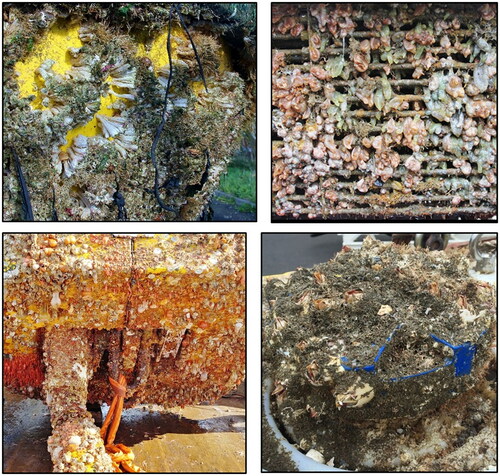
Increased weight and drag from biofouling may compromise MRE device functioning by affecting hydrodynamic performance influencing power delivery, and by increasing structural loading on the device and/or its moorings (Orme et al. Citation2001; Langhamer et al. Citation2009; Walker et al. Citation2014). The economic consequences of poorly managed biofouling include performance reduction, costs incurred during removal and prevention of growth, and replacement of corroded components (Swain Citation1998; Yebra et al. Citation2004; Schultz et al. Citation2011). MRE-specific biofouling issues include: impacts on moving parts unique to these technologies (Tiron et al. Citation2015); the use of novel materials in ways that have not been trialled before (Polagye and Thomson Citation2010); and, deployment into habitats where structures have not been previously installed and studied (e.g. strong tidal flow areas) (Want et al. Citation2017; Sheehan et al. Citation2020). Limitations in effectiveness of antifouling coatings are expected when applied to components featuring greater structural and hydrodynamic complexity, such as ‘niche’ areas, e.g. couplings and manifolds. (Edyvean Citation1987; Coutts and Taylor Citation2004). Antifouling and anti-corrosion efficacy provided by coatings is expected to be further reduced in high-current speeds through greater shear stress and increased rate of antifoulant dissolution (Kiil et al. Citation2002). Coatings may be further compromised by sediment abrasion (Walker et al. Citation2014) with potential impacts on cathodic protection and electrical conductivity (Yerba et al. Citation2004; Klijnstra et al. Citation2017). In addition, the functionality of sensors (e.g. data buoys, acoustic Doppler current profilers, and cameras) used to characterise energy resource and monitor device performance may be compromised by biofouling (Want et al. Citation2017) ().
Figure 1. Biofouling of marine renewable energy infrastructure (clockwise from top left): heavy barnacle fouling after only 8 months deployment of a Waverider buoy used to assess wave resource; tunicates dominating the fouling on a tidal device subunit; barnacles and hydroids on an acoustic Doppler current profiler used to assess tidal current flow; and, heavy animal-dominated fouling on an offshore ‘tether-latch assembly’ mooring system (Tether-latch assembly image courtesy of EMEC).
There are relatively few published studies on biofouling in this sector owing partly to the early technology readiness level of MRE devices, and to commercial sensitivities (Shields et al. Citation2011). Furthermore, in situ studies comparing coating performance in the MRE sector are absent from peer-reviewed literature (Loxton et al. Citation2017). MRE studies have included biofouling assessments of buoys (Langhamer et al. Citation2009; Macleod et al. Citation2016) and have described the role that vessels and harbours, may play in the movement of fouling species (Nall et al. Citation2015). Studies specific to the biofouling in Orkney waters have included: monitoring of intertidal indicator species (Want et al. Citation2014); classification and quantification of fouling on a wave device (Nall et al. Citation2017); and, characterisation of biofouling assemblages at wave, tidal, and harbour sites including devices, fixed infrastructure, data buoys, and sublittoral sensors (Want et al. Citation2017).
Earlier MRE studies in biofouling have chiefly focussed on limited opportunities to observe fouling from seabed moorings and surface-bound floating structures (Langhamer et al. Citation2009; Macleod et al. Citation2016; Nall et al. Citation2017; Want et al. Citation2017; Sheehan et al. Citation2020). One of the key obstacles to studying biofouling in this sector is the challenge of collecting data in high exposure environments. High current flow conditions may not be practical for survey work using divers or ROVs (Gormley et al. Citation2018), and a critical knowledge gap exists in fouling characterisation of MRE structures deployed at ‘mid-depths’, e.g. positioned in the water column where tidal turbines optimally operate (Kolekar and Banerjee Citation2015). While a rich body of biofouling studies on static oil and gas infrastructure now exists (Wolfson et al. Citation1979; Forteath et al. Citation1982; Relini et al. Citation1998; Page et al. Citation2006), the importance of marine fouling in that sector was initially overlooked and underestimated (Edyvean Citation1987). Given the early developmental stage of the MRE sector where installation, operation and maintenance costs are likely to be elevated, comprising a significantly larger proportion of project costs and leading to an increased levelised cost of electricity (LCOE) compared with equivalent energy generation technologies (Ocean Energy Systems Citation2015). As such, the ability to monitor fouling and the capacity to test coating performances in situ in high tidal flow habitats and on moving parts (e.g. rotating blades) is particularly important. This creates strong drivers for developers to pre-emptively design equipment and systems that reduce servicing requirements and costs as an essential part of their economic development (EMEC Citation2014, Topper et al. Citation2019).
This sector would benefit from the ability to gather critical depth and time-dependant data, including seasonal and successional studies, using a monitoring and testing system capable of easy deployment and retrieval, allowing sampling independently of other operations (Underwood and Anderson Citation1994). Early work by Crisp and Stubbings (Citation1957) used panels suspended at the surface in the tidal channel at the Menai Strait, in order to investigate the influence of current flow on barnacle settlement patterns. A mid-depth biofouling monitoring system has recently been deployed at a wave exposed site in Chile which may, in future, be used to test wave energy devices (Navarrete et al. Citation2019, Citation2020). Monitoring seasonal recruitment onto settlement panels of organisms with planktonic larvae may serve as an effective method of identifying important life history stages of problematic fouling species (Sutherland and Karlson Citation1977; Underwood and Anderson Citation1994; Marraffini et al. Citation2017; Susick et al. Citation2020).
Biofouling of Renewable Energy Environments - Marine (BioFREE) is a collaborative project between Heriot Watt University and EMEC. The overarching aim of this project is to address key knowledge gaps of biofouling in the data-poor, high-exposure environments where devices are being deployed. The objectives of the study were to: (1) design and manufacture a standardised monitoring system for deployment and retrieval at appropriate depths within the water column; (2) test the system in high wave energy environments; (3) test the system in high tidal flow environments; (4) present preliminary results following initial deployments of the system, and; (5) discuss these results in the context of the suitability of this system for assessing biofouling at locations of interest to the MRE industry and for long term monitoring of these sites.
Material and methods
The BioFREE monitoring and testing system
To fulfil the key objective of the BioFREE project, a system was designed to be physically robust, to withstand extreme hydrodynamic forces, and statistically robust, accommodating sufficient test panels to allow testing of materials and coatings in a hierarchically-designed study (Townend Citation2002). Additional design factors considered included material selection, cost, and ease of ‘stand-alone’ deployment and retrieval, independent of other marine operations. System design also required that it can be replicated by various manufacturers throughout the world, emphasising the required simplicity of the final units.
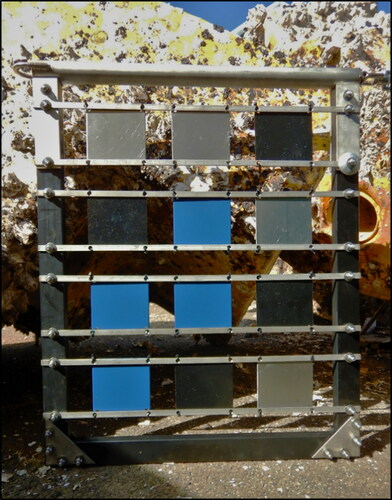
The BioFREE monitoring and testing system consists of a frame (measuring 796 mm (length); 672 mm (height); and, 25 mm (width)) populated with an array of 12 settlement panels. The frame is comprised of high-density polyethylene (HDPE) (Whitford Ltd, UK) except for a single vertical weight-bearing hoist composed of marine grade (316) stainless steel (Hamnavoe Engineering, UK) (). This cylindrical hoist (measuring 672 mm (length); 50 mm (diameter)) is sealed and fitted at top and bottom with steel anchoring points and catalytically protected by a sacrificial anode.
Figure 2. BioFREE biofouling monitoring and testing frame: coating and material testing systems have been designed, manufactured and deployed following extensive consultation with MRE operational staff and developers, hydrodynamicists, and statisticians. In this image, the frame has been rotated 90°, showing the hoist at the top. Note: heavily fouled mooring structures in background.
Extensive consultation was undertaken with marine operational staff and hydrodynamicists in the design of the mooring and recovery component of the BioFREE system with the aim of ensuring survivability over long-term field tests in both tidal and wave dominant sites. Individual component design was considered with respect to buoyancy and drag contribution at sea, including increased buoyancy and reduced drag profile elements in the frame. Tidal stream and wave-induced forces were accounted for in the system design (line length, buoyancy units, frame) and mooring anchor. Installation depths at each test site were considered with regards to mitigating wave-induced forces closer to the surface, especially at the high-wave site; frames were positioned relatively close to the seabed. Specific attention was made to drag forces generated by the tidal stream. Drag forces will act upon all components of the system causing the position and orientation of the frame to shift from vertically above the seabed at slack water, to a more acute angle, closer to the seabed, increasing with tidal velocity. At sufficiently high current flows, the frame could be expected to contact the seabed, possibly damaging the system and affecting collection of fouling data. The analysis, along with the application of a factor of safety (2.0) to account for uncertainties in current flow, drag coefficients and wave forces, informed the final design of the system to ensure survivability at the selected sites.
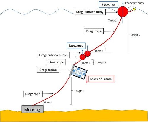
The system is anchored to the seabed via a simple clump weight mooring system (500 kg) attached by shackle to anchoring line leading to the frame hoist. The frame hoist was connected to lines above and below using shackles and thimbles (20 mm). All components were connected using 18 mm polypropylene rope (of near neutral buoyancy), the width chosen for its ease of manual handling, as well as for its high tenacity and lower drag compared with thicker ropes. Subsea buoyancy above the frame is necessary to maintain a near vertical orientation of the array. Buoyancy is provided through frame components and 280 mm subsea trawl floats attached to the hoist by a line extending to a surface buoy, necessary for relocation. A small, 75 mm, ‘recovery’ buoy is attached to the surface buoy to aid in retrieval. A simplified schematic drawing illustrating drag forces and buoyancy used to determine angular deviation of each system component of the deployment system, including connecting rope lengths, is presented in . Modification of Length 1 and Length 3 allow the system to be deployed in varying depths and heights above the seabed, respectively.
Figure 3. Schematic design of the BioFREE monitoring and testing system simplified for clarity. Determination of drag forces and buoyancy on each component was necessary to calculate the maximum angle of displacement (theta) between system components, and the position of frame relative to the seabed.
Materials under investigation
Following discussions with industry developers to identify materials of greatest concern, HDPE, uncoated ‘mild’ steel, and ‘mild’ steel treated with an anti-corrosion coating were selected for settlement studies. Panels measuring 124 × 124 × 3 mm were manufactured by Whitford Ltd (UK). Steel panels (S355) were treated with an experimental, organic polytetrafluoroethylene (PTFE)-based, thin-film protective coating designed by Whitford Ltd. While this coating was primarily designed for its anti-corrosion properties, PTFE-based coatings have been shown to reduce biofouling and may be a cost-effective solution to address both issues (Zhao et al. Citation2005). Using a randomised block experimental design (Townend Citation2002), four pre-weighed panels of each substratum type were assigned positions within each array and secured within BioFREE frames using plastic cable ties.
Study sites
The European Marine Energy Centre operates four test sites in Orkney waters: a full-scale tidal test site at the Fall of Warness (59° 08.852’ N; 002° 48.101’ W); a full-scale wave test site at Billia Croo (55° 58.795’ N; 003° 23.029’ W); a more moderate scale tidal test site at Shapinsay Sound (59° 00.165’ N; 002° 53.183’ W); and a more sheltered wave test site at Scapa Flow (58° 53.657’ N; 002° 57.128’ W) (). Deployment of paired systems occurred at all four EMEC test sites in July 2018 (i.e. T0) using a 26 m Multi-cat vessel (MV C-Odyssey, Leask Marine, UK). Deployment depth varied between sites; maximum height of the frame above the seabed (i.e. Length 3) was adjusted depending on the tidal current profile at each site (). At the Fall of Warness, with current flows approaching 4.0 m s−1, frames were deployed 15 m above the seabed in 40 m of water; at Billia Croo, frames were deployed 3 m above the seabed in 45 m of water; at Shapinsay Sound, with current flows around 1.0 m s−1, frames were deployed 5 m above the seabed in 25 m of water; and at Scapa Flow, frames were deployed 3 m above the seabed in 25 m of water. All sites were similar to one another in distance to shore and sea distance to nearest port. Sea surface temperature in Orkney waters seasonally varies from around 7–13° C; salinity is not expected to vary substantially between these well-mixed, open-water locations with no major freshwater sources within about 50 km (OIC Citation2021). All settlement panels were deployed at aphotic depths in a zone ∼20–40 m below the surface. These depths were selected as best representative of operational conditions of full-scale MRE devices, and to minimise the effects of surface waves on frame movements and survivability.
Figure 4. Map of test sites used by the European Marine Energy Centre: (1) Fall of Warness (59° 08.852’ N; 002° 48.101’ W); (2) Billia Croo (55° 58.795’ N; 003° 23.029’ W); (3) Shapinsay Sound (59° 00.165’ N; 002° 53.183’ W); (4) Scapa Flow (58° 53.657’ N; 002° 57.128’ W).
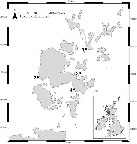
Table 1. Environmental and operational parameters of BioFREE frames deployed at European Marine Energy Centre test sites in July 2018.
Characterisation of biofouling communities
BioFREE systems were recovered approximately every 3 months beginning in October 2018 (i.e. T3), all panels (n = 96) were imaged using a digital SLR camera (dSLR) (Canon 60 D, Japan), and a pre-selected quarter of panels were removed for further analysis to determine species identification and fouling mass. Removed panels were replaced by new panels of the same treatment into the same position in the array. Quarterly study and replacement of selected panels was designed to allow analysis of seasonal recruitment and successional changes in fouling – consideration of seasonality is particularly important in temperate water studies (Underwood and Anderson Citation1994). In this manner, for each seasonal interval, recruitment of biofouling can be observed on substrata provided ‘fresh’ in each season, as well as on substrata pre-fouled during earlier seasons.
Data collection from recovered panels occurred in the laboratory. Panels were immersed in seawater and analysed under a dissecting microscope (Leica M125; 8x-100x magnification). A comprehensive list of macrofouling species present and species richness (S) was determined for each panel following identification to lowest practicable taxonomic level, ideally to species level. The analysis team was comprised of trained experts in major fouling groups including barnacles, bryozoans, hydroids, and macroalgae. Photographic records were made using a dSLR (Leica MC170 HD, Germany). The most dominant species were identified based on qualitative assessment of percentage cover contribution to total biofouling.
Each panel was weighed in air to determine wet mass of biofouling. Each panel was then placed in an oven (∼70 °C) to remove all water and reweighed until a stable dry weight could be recorded. Biofouling mass was determined using a 500 g capacity balance (Oertling OB152, UK) recorded to the closest 0.01 g. Weight of recovered panels was compared against pre-deployed weight to determine fouling growth and expressed as kg m−2.
Statistical analysis
Analysis of variance of biofouling variables was undertaken using the ‘lm’ function in the R statistical package (R Core Team Citation2020). Dry and wet weights of biofouling matter were log-transformed for normality after inspection of model diagnostics. Frame was treated as being nested within site as a factor variable. Type II tests were undertaken using the ‘ANOVA’ function of the car package (Fox and Weisberg Citation2019). Materials were treated as being fully randomised among the rows and columns of the frames.
Statistical analysis of fouling assemblage composition was performed on species occurrence data using Primer v6 software (Clarke and Gorley Citation2006). Bray–Curtis similarities (Digby and Kempton Citation1987) were used to quantify resemblance of species presence–absence composition between survey samples between sites and over the two sampling periods. Survey samples with similar species were identified using average-linkage cluster analysis and non-metric multi-dimensional scaling (MDS). Analysis of similarity (ANOSIM) function was used to explore how biofouling assemblages differed between test sites and over time. Similarity percentage analysis (SIMPER) was used to identify which species were most responsible for differences between groupings (Clarke Citation1993).
Results
The BioFREE monitoring and testing system
In mid-October 2018, following 3 months of deployment (i.e. T3), all systems were successfully recovered. The subsequent retrieval was delayed, owing to inclement winter sea conditions, occurring in March 2019 (i.e. T8). During the latter recovery operation, the marker buoy from one of the Billia Croo systems could not be relocated and the panels from this frame could not be retrieved. The reason for this apparent loss is unknown but may be the result of vessel entanglement with the surface buoy. Based on recovery of all 8 frames at T3 (Oct. 2018) and 7 of the 8 frames at T8 (Mar. 2019), in total 15 out of 16 retrievals were successfully completed, giving an overall recovery rate of 94%.
Materials under investigation
Synoptic images of one frame representative of each site at recovery intervals T3 (Oct. 2018) and T8 (Mar. 2019) are presented in . In these images, panel composition can be identified by colour with HDPE as black, coated steel as blue, and uncoated steel as rust. Oxygen levels were not recorded during these studies, however, observations of the condition of retrieved panels indicated higher levels of oxidation of uncoated steel panels at the Fall of Warness and Shapinsay Sound, compared with Billia Croo and Scapa Flow sites This is consistent with the expectation of greater oxidation occurring in high current flow sites (). Oxidation of these surfaces led to extensive loss of corroded outer layers of uncoated steel panels preventing accurate assessment of biofouling; these panels were not included in further analysis. In continuing studies beginning in March 2019, panels constructed of uncoated ‘mild’ steel are replaced by uncoated marine grade (316) stainless steel. A comparison of biofouling wet and dry weight between substrata recovered for study at T3 (Oct. 2018) and T8 (Mar. 2019) is shown in .
Figure 5. Synoptic images of BioFREE settlement panels deployed at EMEC test sites between July 2018 and March 2019. Lefthand side: retrieval in October 2018; righthand side: retrieval in March 2019. From the top: Fall of Warness; Billia Croo; Shapinsay Sound; and Scapa Flow.
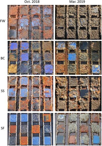
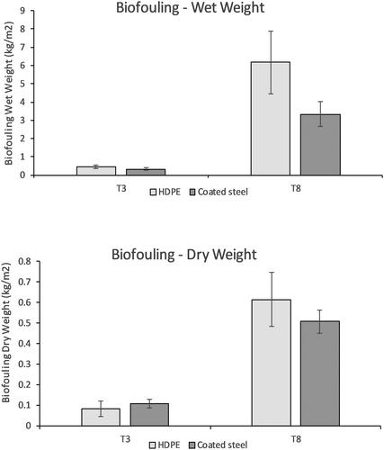
Figure 6. Effects of substratum on biofouling. Mean wet weight (g) of biofouling on panels of high-density polypropylene (HDPE) and coated steel treated with an anti-corrosion agent deployed at EMEC test sites from mid-July (n = 8) to mid-October 2018 (n = 7) (±SE).
Study sites
Fouling wet weight on settlement panels recovered for study from each test site at T3 (Oct. 2018) and T8 (Mar. 2019) is presented in . The greatest initial settlement and growth occurring up to T3 (Oct. 2018) was observed on HDPE panels deployed at the full-scale tidal test site at the Fall of Warness. The second greatest increase in wet weight was recorded on HDPE panels deployed at the scale tidal test site in Shapinsay Sound. The most striking contrast at T3 (Oct. 2018) between wet weight of biofouling between test substrata was initially observed at the Fall of Warness, although not of statistical significance. At this time, the mean weight from fouling on settlement panels was 0.72 kg m−2 on HDPE and 0.20 kg m−2 on coated steel (F1,2 = 2.9122, p = 0.230).
Figure 7. Biofouling wet weight recorded at EMEC test sites. Mean wet weight (g) of biofouling from replicate panels (2) deployed at EMEC test sites from mid-July 2018 to March 2019. FW: Fall of Warness; BC: Billia Croo; SS: Shapinsay Sound; and, SF: Scapa Flow (±S.E.). Top: high-density polypropylene (HDPE) panels; bottom: coated steel (CS), treated with anti-corrosion agent.
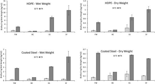
At T8 (Mar. 2019), the greatest amount of fouling was observed on HDPE panels at the Scapa Flow and Shapinsay Sound sites; the least amount of fouling was observed at the highly exposed wave test site at Billia Croo. By T8 (Mar. 2019), the greatest contrast in fouling growth between test substrata was observed at the scale tidal test site at Shapinsay Sound: mean wet weight of fouling on panels was 7.54 kg m−2 on HDPE and 3.16 kg m−2 on coated steel (F1,2 = 91.272, p = 0.0108).
Characterisation of biofouling communities
Species richness (S) and a preliminary identification of the most abundant ‘pioneer’ species are presented in . Images of some of these key early successional fouling species are presented in . As a general observation, late summer fouling was dominated by a turf of colonial hydroids. This was particularly apparent at both tidal test sites where fouling during this period was dominated by a thick turf of the hydroid Ectopleura larynx; hydroid fouling was much reduced at the scale wave test site at Scapa Flow. This location is the most sheltered and features the lowest tidal flow rate of the four study sites. Instead, initial fouling at the Scapa Flow site was dominated by the encrusting calcareous tubeworm Spirobranchus triqueter. The greatest number of species were identified at Billia Croo (16), and the fewest at the Fall of Warness (8).
Figure 8. Key early successional fouling species on MRE substrata in Orkney waters include (from left): the saddle oyster Anomia ephippium; colonies of bryozoan such as Celleporina hassalli; the hydroid Ectopleura larynx; and the tube-building amphipod Jassa falcata. Scale bar 0–5 mm.
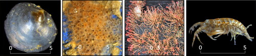
Table 2. Species richness (S) and results of most abundant ‘pioneer’ fouling organisms recruiting to new panels deployed at wave and tidal test sites operated by the European Marine Energy Centre.
During the autumn recruitment season, biofouling on new panels was dominated at all sites by colonies of the tube-forming amphipod Jassa falcata. The colonial sea-squirt Diplosoma spongiforme was a major contributor to pioneer fouling during this season at the high tidal flow sites. Small colonies of several species of bryozoans were common at all locations. The organisms with the highest profile observed were solitary tunicates, e.g. Ascidiella aspersa. These organisms began settling before T3 (Oct. 2018) and grew into dominance by T8 (Mar. 2019) with the most pronounced fouling occurring at the relatively sheltered site in Scapa Flow. Species richness generally increased over the study period.
Noticeably absent from all panels deployed from July to March were barnacles – one of the key groups of fouling organisms. This illustrates the importance of seasonality in fouling settlement; barnacle fouling is expected to dominate spring and early summer seasons (Southward Citation2008). In combination with additional biofouling studies (Want et al. Citation2017), >200 marine fouling organisms have been identified in Orkney waters on artificial substrates used routinely by the MRE industry.
Statistical analysis
Accumulation of material between periods was found to be the dominant pattern in dry weight, with some differences in the rate of accumulation between sites ( F3,10 = 4.283, p = 0.035). Wet weight showed similar patterns, but with some evidence of differences between materials depending on both site and period ( F3,10 = 5.433, p = 0.018).
Table 3. Analysis of variance of log-transformed biofouling weight, using Type II tests: (a) dry weight; (b) wet weight.
The multi-dimensional scaling (MDS) plot of fouling communities shows clear distinctions between deployments at EMEC test sites over the study period (). The 2-D stress of the MDS plot is 0.05, indicating that the similarities between samples are well represented in the plot (Clarke Citation1993). Analysis of average-linkage similarities indicated distinct clusters of biofouling assemblages associated with high exposure test sites and more sheltered scale test sites at T3 (Oct. 2018). At T8 (Mar. 2019), assemblage clusters further diverged between the more sheltered test sites.
Figure 9. MDS plot using biofouling community data collected using replicate BioFREE systems at test sites operated by the European Marine Energy Centre. BC: Billia Croo; FW: Fall of Warness; SF: Scapa Flow; and SS: Shapinsay Sound. A: October 2018; B: March 2019. Ellipses represent groups identified by average-linkage cluster analysis based on Bray–Curtis similarities.
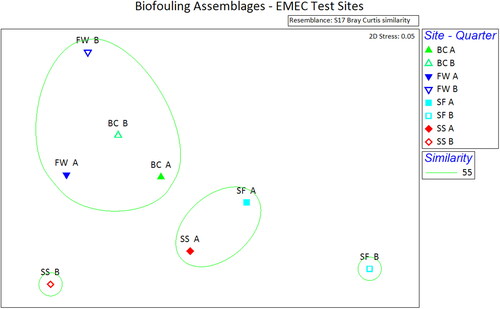
ANOSIM confirmed that there was a highly significant statistical separation in community composition between all groups (global R = 0.929; p = 0.001). ANOSIM based on each factor indicated highly statistically significant between sites (global R = 0.535; p = 0.001), but greater mixing was indicated between periods, although group separation was still statistically significant (global R = 0.253; p = 0.03). Pairwise testing between sites confirmed that the biofouling assemblages at the highest exposure sites at Billia Croo and the Fall of Warness were most similar; the greatest differences in assemblages were observed in pairwise testing between higher exposure versus more sheltered sites ().
Table 4. One-way analysis of similarities (ANOSIM) showing the R statistic (significance level) comparing biofouling assemblages surveyed from wave and tidal test sites operated by the European Marine Energy Centre.
SIMPER analysis of dissimilarities in fouling assemblages between deployment periods identified that assemblages recorded at T3 (Oct. 2018) across the test sites featured comparative abundances of the colonial hydroids Ectopleura larynx, Obelia dichotoma, and Plumularia setacea, and the bryozoan Electra pilosa. At T8 (Mar. 2019), a more diverse assemblage was present with calcareous tubeworms of the genus Hydroides and the colonial tunicate Diplosoma spongiforme making the greatest contribution to dissimilarities between time periods. The main species contribution of fouling assemblage similarities observed at each test sites were: Billia Croo with the saddle oyster Anomia ephippium, the bryozoans Celloporella hyalina, Electra pilosa and Tubilopora lilacea, Diplosoma spongiforme, the arthropods Jassa falcata and Nymphon gracile, and the calcareous polychaete Spirobranchus triqueter; Fall of Warness with Celloporella hyalina, Jassa falcata, and the cocoon-dwelling polychaete Eusyllis lamelligera; Scapa Flow with Anomia ephippium, the solitary tunicate Ascidiella aspersa, and Spirobranchus triqueter, and; Shapinsay Sound with Ascidiella aspersa and Jassa falcata.
Discussion
Published studies using independently deployed panels in habitats important to the MRE sector are limited. Early in situ experiments were conducted using surface supported panels with the purpose of studying barnacle orientation during settlement in a tidal channel at the Menai Strait in North Wales with an estimated flow rate of 1.2 m s−1 (Crisp and Stubbings Citation1957). Navarrete et al. (Citation2019) recently reported biofouling at wave-exposed locations off the coast of Chile using a subsea frame populated with panels constructed from three substratum types, albeit at a location with reduced wave exposure (maximum wave height averaging about 2.5 m) relative to Billia Croo (Orkney) and without design elements to allow survival in high tidal flows. In the present study the BioFREE system has successfully been deployed and retrieved for the purpose of capturing critical data in these highly energetic environments, with a 94% recovery of settlement panels through harsh winter conditions in the North Atlantic. Studies of in situ biofouling in high tidal current flows and extreme wave environments typically rely on limited opportunities to examine fouling, i.e. infrequent access to surface deployments or seabed moorings during maintenance and other operations (Langhamer et al. Citation2009; Macleod et al. Citation2016; Nall et al. Citation2017; Want et al. Citation2017). In contrast, the BioFREE system is independently deployed and retrieved, allowing greater operational flexibility and experimental control regarding location and timing of data collection. Using this system, fouling data can be captured from appropriate chosen depth within the water column – there may be wave-induced constraints created by deploying too near the surface and frame placement too close to the anchoring is at risk of making contact with the seabed, especially in high currents.
Managing extreme drag encountered in high-tidal flows has played a major role in design of the BioFREE system. By necessity, the panel array is a as large as possible without exceeding the buoyancy capacity provided by system components; in less challenging areas, greater capacity for testing and replication could be possible through design of a larger array. Calculations of drag and buoyancy provided estimations of appropriate frame position relative to the seabed at different tidal velocities. These calculations mitigated against the risk of failure of the system and allowed successful deployment and survivability at locations with tidal currents of up to 3.0 m s−1 and mean significant wave height of up to 3.0 m, far in excess of previously reported studies.
Wave-induced forces may have important hydrodynamic consequences to the benthic community even in relatively deep waters (Denny Citation1987). The role that wave-induced oscillations through the water column may have on biofouling settlement and growth is an important knowledge gap concerning subsurface infrastructure (Navarrete et al. Citation2020). Earlier studies by Want et al. (Citation2017) reported predictable biofouling assemblages on infrastructure with contrasting wave climates. These findings were based on presence/absence data rather than quantifiable measurement of biofouling weight or species abundance and were not predominantly based on mid-depth surveys. In macroalgal aquaculture applications, moderate wave exposure appears to reduce biofouling (Andersen et al. Citation2011; Peteiro and Freire Citation2013) and algal biomass is expected to be reduced with greater wave exposure (England et al. Citation2008). The role of wave exposure as a major determinant of hard substratum assemblages and as a limiting force in growth of hard substratum organisms is well established (Lewis Citation1964; Denny Citation1999; Blanchette et al. Citation2000). In the current studies, after 8 months of deployment, fouling mass at the high wave-exposure site at Billia Croo was markedly less than the other sites and dominated by low-profile encrusting species.
Following discussion with MRE developers and EMEC, substrata relevant to the sector were selected for manufacture of settlement panels. These were employed as representative surfaces for the purpose of collecting preliminary biofouling data while trialling the operation of the monitoring and testing system. In future, performance testing of any materials and protective coatings can be fitted to this system as determined by researcher interests. Additional relevant components, identified by the industry, can be fitted to the system for further testing. In this study, fouling was greater on uncoated HDPE panels when compared with coated steel panels. Differences in fouling between these substrata were most apparent at sites of greatest tidal flow, at least in the short-term. While it might be expected that antifouling properties associated with the coated steel may account for observed reductions in fouling compared with HDPE, in the current trial study, there are not the controls necessary to test whether these differences are owing to substratum type or coating treatment. Results from designated control panels were excluded from this study after it was discovered that steel of an insufficient marine grade was erroneously supplied leading to unacceptable corrosion (Melchers and Jeffrey Citation2005) creating an unstable substratum for biofouling organisms.
Initially, at T3 (Oct. 2018), fouling was greatest on HDPE panels deployed at tidal tests sites when compared with wave test sites and dominated by the hydroid Ectopleura larynx. The greatest differences in fouling between substrata were seen at the high tidal flow sites at the Fall of Warness and Shapinsay Sound. These results suggest that, while flow conditions at this site may favour settlement and growth on HDPE panels, the short-term efficacy of protective coatings applied to the steel panels may be most apparent in high-tidal flows. In other words, high current flow may promote recruitment and growth, i.e. through enhanced larval and nutrient transport (Bourget and Crisp Citation1975; Roughgarden et al. Citation1988; Gaylord and Gaines Citation2000; van der Molen et al. Citation2018), but also create sufficient drag forces to dislodge certain organisms adhering to surfaces protected by fouling-release coatings. Considerable caution must be used in interpreting comparisons in this limited trial.
At T8 (Mar. 2019), the greatest growth in fouling was observed at more sheltered sites where large solitary sea-squirts proliferated. These sites also featured the biggest differences in biofouling mass between HDPE and coated steel panels observed over this interval. It is plausible that this may be the result of enhanced prevention of attachment by large organisms on protected surfaces. At T8 (Mar. 2019), there were no longer differences in fouling mass between HDPE and coated steel panels at the Fall of Warness. It is not clear why this is but perhaps the initial efficacy of the PTFE-based coating at this site was reduced after longer exposure to this challenging habitat.
While the system has been designed to be as symmetrical as possible and no differences in species diversity or compositions were observed when comparing the front and back of individual panels, it is conceivable that differences in fouling might occur between sides. Additional analysis is necessary to test the presence of an ‘edge’ effect which might be a factor in fouling comparisons between panels located in the centre vs the periphery of the frame (Lim et al. Citation2014), as well as the potential effects of position relative to the frame hoist in the event of possible flow-induced vibrations and location-specific turbulence, especially in higher tidal flow conditions. While these additional and necessary analyses are not yet completed there is no preliminary evidence of differences in fouling on BioFREE systems based on panel position. Fluid dynamic modelling of flow through the system with and without biofouling is planned.
Biofouling assemblages
Fouling organisms may be highly specific to location based on a variety of physical and biological factors including depth, substratum orientation, salinity, temperature, distance to shore, competition, and larval and nutrient supply (Connell Citation1961; Page Citation1986; Lewbel et al. Citation1987; Roughgarden et al. Citation1988; Smith and Witman Citation1999; Gaylord and Gaines Citation2000; Glasby and Connell Citation2001). Some studies have demonstrated predictability in the composition and sequence of fouling communities (Sutherland and Karlson Citation1977; Bram et al. Citation2005), perhaps owing to relatively stable physical factors (Vance Citation1988). However, short-term changes in supply of larvae and nutrients might be expected to contribute to considerable variation in successional stages of fouling as found in other studies (Osman Citation1977; Dean and Hurd Citation1980). Dominant fouling species may also vary considerably based on timing of deployment, i.e. seasonality of settlement is often highly species-specific (Forteath et al. Citation1984; Underwood and Anderson Citation1994; Bram et al. Citation2005). In the current studies, contrasting tidal flow and wave regimes but similarities in other physical factors between sites, suggests that hydrodynamic forces may play an important role in determining biofouling assemblages. Drag, lift, and acceleration forces will impact survivability of organisms settling onto these substrata (Denny Citation1987) and tidal and wave regimes will influence the supply of nutrients and larvae (Roughgarden et al. Citation1988; Gaylord and Gaines Citation2000).
The current studies corroborate earlier work identifying predictable species assemblages and abundances at sites with contrasting hydrodynamic conditions in Orkney waters. Surface devices and buoys will often feature considerable fouling from several macroalgal species, including larger kelps such as Laminaria hyperborea, and, in more wave exposed areas, Alaria esculenta (Want et al. Citation2017). Several animals are key foulers on intertidal and shallow sublittoral structures at these test sites including: the barnacle, Semibalanus balanoides; the blue mussel, Mytilus edulis; and hydroids, such as Amphisbetia operculata and Ectopleura larynx (Want et al. Citation2017). The effects of light and wave exposure will decrease with depth; in deeper waters, the fouling assemblage rapidly transitions to an animal-dominated group of key fouling organisms. At more sheltered, deeper water MRE ‘scale’ sites in Orkney, biofouling is dominated by relatively large solitary tunicates, especially Ascidiella aspersa. In faster current speeds, (e.g. approaching 0.5 m s−1 at the full-scale wave test site at Billia Croo) aphotic fouling assemblages comprise a mixture of soft-bodied animals such as Alcyonium digitatum, Metridium dianthus and several species of hydroids, and hard-bodied encrusting animals including barnacles, bryozoans, and saddle oysters (Anomia ephippium). As current speeds increase, soft-bodied organisms are less likely to be found (except in limited ‘niche spaces of relative shelter) presumably because of direct hydrodynamic stress or indirectly through current-driven scour (Coutts et al. Citation2010). With less competition for space resource, hard-bodied foulants flourish in higher flow conditions (e.g. >2.0 m s−1), such as those targeted by tidal energy technologies, i.e. the full-scale tidal test site at the Fall of Warness. Many of these encrusting species (i.e. bryozoan colonies and saddle oysters) are of small size and low profile, with relatively minor hydrodynamic and hydrostatic impacts expected (although component corrosion may be an ongoing issue with unmanaged biofouling). From a hydrodynamic standpoint, when compared with other fouling organisms in this environment, high profile, non-compliant barnacle shells create greater impacts on drag (Denny Citation1987; Gaylord Citation2000). The dominant fouling role of the sublittoral barnacle Chirona hameri in high-current velocities and its large size relative to most fouling organisms makes it an obvious concern to technologies working in tidal environments in the North Atlantic (Want et al. Citation2017).
The current studies have found that abundant early recruitment of hydroids, as well as other key ‘pioneer’ organisms such as encrusting calcareous tube-worms (e.g. Spirobranchus triqueter), bryozoans (e.g. Celleporina hassalli) and saddle oysters (Anomia ephippium) dominate the fouling assemblages at these locations. Hydroids (especially Ectopleura larynx) typically form a turf, often associated with colonies of tube-building amphipods (e.g. Jassa falcata) (Bradshaw et al. Citation2003; Page et al. Citation2008). This turf forms the major part of autumnal macrofouling assemblages recorded at EMEC test sites, although notably less abundant at the Scapa Flow test site featuring relatively little tidal flow. While fouling from higher-profile, non-compliant, encrusting organisms (e.g. barnacles) may produce a greater hydrodynamic performance penalty than more flexible, turf-forming species such as hydroids (Christie and Dalley Citation1987; Denny Citation1987; Schultz Citation2004), the latter group of foulants provide biogenic structure (Turner et al. Citation1999; Bradshaw et al. Citation2003) which may substantially increase drag and mass, and promote corrosion of unprotected components. Early successional ‘pioneers’ may also play an important role, inhibiting other species by dominating space resource (Connell and Slatyer Citation1977; Sutherland and Karlson Citation1977). For example, studies of seasonal settlement of oysters and macroalgae found subsequent recruitment of barnacles was reduced (Underwood and Anderson Citation1994; Pham et al. Citation2011).
While data collected using the BioFREE system has allowed detailed characterisation of seasonal and successional biofouling at these deployment sites, the preliminary findings discussed here represent limited studies as part of system sea-trials during late summer to spring seasons when rates of settlement and growth are expected to decline. The main fouling species during this period may not be representative of the overall key foulants whose impacts have greatest effect upon, for example, device performance . For example, balanoid barnacles which often form major components of fouling communities typically have settlement periods in spring and summer (Southward Citation2008). Completion of data collection over at least an annual cycle is necessary to understand issues of seasonality and successional changes in fouling communities (Underwood and Anderson Citation1994; Jenkins and Martins Citation2010). Longer term studies are required to understand the dynamics in the ecological processes of the biofouling communities (Osman Citation1977; Dean and Hurd Citation1980).
Future studies and directions
The BioFREE system will be developed further by investigating its behaviour underwater with specific regards to the effects of surface waves and peak tides on frame position within the water column, and to the degree of ‘strumming’ and frame motion which may occur in high tidal currents. Attachment of pressure transducers in future studies allowing the position of the frame relative to the surface to be tracked throughout the tidal cycle, will provide further detailed data regarding the behaviour of the frame in different environmental conditions, e.g. such as those likely to be experienced in future by floating offshore wind developments. This may lead to design modifications allowing greater testing capacity by expanding frame size; ideally, sufficient capacity for a Latin-square design of panel placement is recommended (Benschop et al. Citation2018). Options are being considered to mitigate loss of surface buoys necessary for retrieval. Potential choices include the use of acoustic release systems, adding redundancy to the retrieval system, and deploying additional systems to compensate for potential losses. Further data analysis will be conducted on each panel using automated image analysis to quantifiably determine the percentage cover of all macrofouling species using random-dot image analysis (Meese and Tomich Citation1992; Drummond and Connell Citation2005).
Summary
Success of the emerging MRE and offshore floating wind industry depends on maximising energy capture and lowering the levelized cost of electricity generation. Growth of fouling organisms leads to reduced efficiency of energy capture, accelerated corrosion of subsea structures, increased loadings on cables, as well as affecting accuracy of sensors used to assess performance and the hydrodynamic resource (Orme et al. Citation2001; Langhamer et al. Citation2009; Walker et al. Citation2014; Want et al. Citation2017); existing antifouling and corrosion strategies are costly and time consuming, impacting capital and operational expenses (Yebra et al. Citation2004; Schultz et al. Citation2011). Purposeful collection of biofouling data including testing antifouling coatings, material choices, and coating application methods will contribute further to reducing costly impacts of marine growth. BioFREE frames may provide rigorous in situ studies of both biofouling and coating performance necessary for their evaluation in high-tidal flow and extreme wave conditions world-wide. When combined with a greater understanding of biofouling processes in these environments, developers can use wider project design and operational strategies to avoid and minimise impacts (Morandeau et al. Citation2013; Gray et al. Citation2017), and avoiding operational costs associated with reactive maintenance and servicing of devices (EMEC Citation2014; Topper et al. Citation2019). Avoiding periods of major settlement, and timing cleaning operations to maximise removal of the most problematic foulants, may form part of an effective scheduling strategy to minimise the consequences from fouling. Improved device efficiency and maintenance will provide greater harvesting of energy creating greater return on investments while also delivering substantial benefits in terms of reduced annual carbon emissions (EMEC Citation2020; SIMEC Citation2020).
While these studies have focussed on less well-studied habitats used by the MRE sector, there are broader implications of biofouling impacts and mitigations, e.g. the loading and drag consequences of fouling on mooring functioning and survivability. Capturing biofouling data from hard-to-access marine habitats and providing a platform for testing coatings and materials are also important objectives for developers of floating wind, floating solar and aquaculture installations.
Acknowledgements
Many thanks to the following organisations and individuals: EMEC hosted the Innovation Placement, provided substantial in-kind support and were involved in continual dialogue to project steer from an end-user perspective, for support during design of mooring and retrieval system, and during offshore work to deploy and recover the BioFREE systems; international partners included Prof. Yusaku Kyosuko (Japan), Dr Sergio Navarette (Chile), and Dr Sarah Henkel (USA); bespoke frame components were produced by Hamnavoe Engineering; mooring system construction, boat work and deployment provided by Leask Marine; assistance provided by intern Edouard DuTemple from École Supérieure d’Ingénieurs en Électrotechnique et Électronique, Paris. Thanks also to the anonymous reviewers who have taken the time to provide critical input which has improved this manuscript.
Disclosure statement
No potential conflict of interest was reported by the author(s).
Additional information
Funding
References
- Allan G, Eromenko I, McGregor P, Swales K. 2011. The regional electricity generation mix in Scotland: a portfolio selection approach incorporating marine technologies. Energ Policy. 39:6–22. doi:10.1016/j.enpol.2010.08.028
- Andersen G, Steen H, Christie H, Fredriksen S, Moy FE. 2011. Seasonal patterns of sporophyte growth, fertility, fouling, and mortality of Saccharina latissima in Skagerrak, Norway: implications for forest recovery. J Mar Biol. 2011:1–8. doi:10.1155/2011/690375
- Arup. 2016. Review of renewable electricity generation cost and technical assumptions. DECC. [accessed 2020 May 12]. https://www.gov.uk/government/publications/.
- Benschop HO, Guerin AJ, Brinkmann A, Dale ML, Finnie AA, Breugem WP, Clare AS, Stübing D, Price C, Reynolds KJ. 2018. Drag-reducing riblets with fouling-release properties: development and testing. Biofouling. 34:532–544. doi:10.1080/08927014.2018.1469747
- Blanchette CA, Thornber C, Gaines S. 2000. Effects of wave exposure on intertidal fucoid algae. Proc Califor Isl Symp. 5:347–355.
- Bourget E, Crisp D. 1975. Factors affecting deposition of the shell in Balanus balanoides (L.). J Mar Biol Ass. 55:231–249. doi:10.1017/S0025315400015873
- Bradshaw C, Collins P, Brand AR. 2003. To what extent does upright sessile epifauna affect benthic biodiversity and community composition? Mar Biol. 143:783–791. doi:10.1007/s00227-003-1115-7
- Bram JB, Page HM, Dugan JE. 2005. Spatial and temporal variability in early successional patterns of an invertebrate assemblage at an offshore oil platform. J Exp Mar Biol Ecol. 317:223–237. doi:10.1016/j.jembe.2004.12.003
- Christie AO, Dalley R. 1987. Barnacle fouling and its prevention In: A.O. Christie, R. Dalley, editors. Barnacle Biol Routledge; p. 419–433.
- Clarke KR. 1993. Non-parametric multivariate analyses of changes in community structure. Austral Ecol. 18:117–143. doi:10.1111/j.1442-9993.1993.tb00438.x
- Clarke KR, Gorley RN. 2006. PRIMER v6: user manual/tutorial. Plymouth: PRIMER-E; p. 192.
- Connell JH. 1961. Effects of competition, predation by Thais lapillus, and other factors on natural populations of the barnacle Balanus balanoides. Ecol Monogr. 31:61–104. doi:10.2307/1950746
- Connell JH, Slatyer RO. 1977. Mechanisms of succession in natural communities and their role in community stability and organization. Am Nat. 111:1119–1144. doi:10.1086/283241
- Cooper SJ, Hammond GP. 2018. Decarbonising’ UK industry: towards a cleaner economy. I Civil Eng–Energy. 171:147–157. doi:10.1680/jener.18.00007
- Coutts A, Richard DM, Piola F, Hewitt CL, Connell SD, Gardner JPA. 2010. Effect of vessel voyage speed on survival of biofouling organisms: implications for translocation of non-indigenous marine species. Biofouling. 26:1–13. doi:10.1080/08927010903174599
- Coutts ADM, Taylor MD. 2004. A preliminary investigation of biosecurity risks associated with biofouling on merchant vessels in New Zealand. New Zeal J Mar Fresh. 38:215–229. doi:10.1080/00288330.2004.9517232
- Crisp DJ, Stubbings HG. 1957. The orientation of barnacles to water currents. J Anim Ecol. 26:179–196. doi:10.2307/1788
- Dean TA, Hurd LE. 1980. Development in an estuarine fouling community: the influence of early colonists on later arrivals. Oecologia. 46:295–301. doi:10.1007/BF00346255
- Denny MW. 1987. Life in the maelstrom: the biomechanics of wave-swept rocky shores. Trends Ecol Evol. 2:61–66. doi:10.1016/0169-5347(87)90150-9
- Denny MW. 1999. Are there mechanical limits to size in wave-swept organisms? J Exp Biol. 202:3463–3467. doi:10.1242/jeb.202.23.3463
- Digby PGN, Kempton RA. 1987. Multivariate analysis of ecological communities. London: Chapman and Hall.
- Drummond SP, Connell SD. 2005. Quantifying percentage cover of subtidal organisms on rocky coasts: a comparison of the costs and benefits of standard methods. Mar Freshwater Res. 56:865–876. doi:10.1071/MF04270
- Edyvean RGJ. 1987. Biodeterioration problems of North Sea Oil and gas production—a review. Int Biodeterior. 23:199–231. doi:10.1016/0265-3036(87)90002-9
- EMEC. 2014. Performance review of maritime support services for Orkney. Summary report. [accessed 2020 May 12]. www.emec.org.
- EMEC. 2020. [accessed 2020 May 12]. www.emec.org.
- England PR, Phillips J, Waring JR, Symonds G, Babcock R. 2008. Modelling wave-induced disturbance in highly biodiverse marine macroalgal communities: support for the intermediate disturbance hypothesis. Mar Freshwater Res. 59:515–520. doi:10.1071/MF07224
- Forteath GNR, Picken B, Ralph R, Williams J. 1982. Marine growth studies on the North Sea oil. Mar Ecol Prog Ser. 8:61–68. doi:10.3354/meps008061
- Forteath GNR, Picken GB, Ralph R. 1984. Patterns of macrofouling on steel platforms in the central and northern North Sea. In: Lewis JR, Mercer AD, editors. Corrosion and marine growth on offshore structures. Chichester: Ellis Horwood Limited; p. 11–22.
- Fox J, Weisberg S. 2019. An R companion to applied regression. 3rd ed. Thousand Oaks (CA): Sage. [accessed 2020 May 12]. https://socialsciences.mcmaster.ca/jfox/Books/Companion/.
- Gaylord B. 2000. Biological implications of surf‐zone flow complexity. Limnol Oceanogr. 45:174–188. doi:10.4319/lo.2000.45.1.0174
- Gaylord B, Gaines SD. 2000. Temperature or transport? Range limits in marine species mediated solely by flow. Am Nat. 155:769–789. doi:10.1086/303357
- Glasby TM, Connell SD. 2001. Orientation and position of substrata have large effects on epibiotic assemblages. Mar Ecol Prog Ser. 214:127–135. doi:10.3354/meps214127
- Gormley K, McLellan F, McCabe C, Hinton C, Ferris J, Kline DI, Scott BE. 2018. Automated image analysis of offshore infrastructure marine biofouling. JMSE. 6:2. doi:10.3390/jmse6010002
- Gray A, Dickens B, Bruce T, Ashton I, Johanning L. 2017. Reliability and O&M sensitivity analysis as a consequence of site specific characteristics for wave energy converters. Ocean Eng. 141:493–511. doi:10.1016/j.oceaneng.2017.06.043
- Jenkins SR, Martins GM. 2010. Succession on hard substrata. In: Biofouling. Oxford: Wiley-Blackwell; p. 60–72.
- Kern F, Rogge KS. 2016. The pace of governed energy transitions: agency, international dynamics and the global Paris agreement accelerating decarbonisation processes?Energ Res Soc Sci. 22:13–17. doi:10.1016/j.erss.2016.08.016
- Khan N, Kalair A, Abas N, Haider A. 2017. Review of ocean tidal, wave and thermal energy technologies. Renew Sust Energ Rev. 72:590–604. doi:10.1016/j.rser.2017.01.079
- Kiil S, Dam-Johansen K, Weinell CE, Pedersen MS, Codolar SA. 2002. Dynamic simulations of a self-polishing antifouling paint exposed to seawater. J Coatings Tech. 74:45–54. doi:10.1007/BF02698368
- Klijnstra J, Zhang X, van der Putten S, Röckmann C. 2017. Technical risks of offshore structures. In: Holm P, Buck BH, Langan R, Nevejan N, Wille M, Chambers MD, Chopin T, Goseberg N, Heasman K, Fredriksson D, Fredheim A, editors. Aquaculture perspective of multi-use sites in the open ocean. Berlin: Springer; p. 115–127.
- Kolekar N, Banerjee A. 2015. Performance characterization and placement of a marine hydrokinetic turbine in a tidal channel under boundary proximity and blockage effects. Appl Energ. 48:121–133. doi:10.1016/j.apenergy.2015.03.052
- Langhamer O, Wilhelmsson D, Engström J. 2009. Artificial reef effect and fouling impacts on offshore wave power foundations and buoys–a pilot study. Estuar Coast Shelf S. 82:426–432. doi:10.1016/j.ecss.2009.02.009
- Lewbel GS, Howard RL, Gallaway BJ. 1987. Zonation of dominant fouling organisms on northern Gulf of Mexico petroleum platforms. Mar Environ Res. 21:199–224. doi:10.1016/0141-1136(87)90066-3
- Lewis JR. 1964. The ecology of rocky shores. London: Hodder & Stoughton.
- Lim CS, Lee SS, Leong W, Xian YN, Teo SL. 2014. A short review of laboratory and field testing of environmentally benign antifouling coatings. Indian J Geo-Mar Sci. 43:2067–2074.
- Loxton J, Macleod AK, Nall CR, McCollin T, Machado I, Simas T, Vance T, Kenny C, Want A, Miller RG. 2017. Setting an agenda for biofouling research for the marine renewable energy industry. Int J Mar Energ. 19:292–303. doi:10.1016/j.ijome.2017.08.006
- Macleod AK, Stanley MS, Day JG, Cook EJ. 2016. Biofouling community composition across a range of environmental conditions and geographical locations suitable for floating marine renewable energy generation. Biofouling. 32:261–276. doi:10.1080/08927014.2015.1136822
- Marraffini ML, Ashton GV, Brown CW, Chang AL, Ruiz GM. 2017. Settlement plates as monitoring devices for non-indigenous species in marine fouling communities. MBI. 8:559–566. doi:10.3391/mbi.2017.8.4.11
- Meese RJ, Tomich PA. 1992. Dots on the rocks: a comparison of percent cover estimation methods. J Exp Mar Biol Ecol. 165:59–73. doi:10.1016/0022-0981(92)90289-M
- Melchers RE, Jeffrey R. 2005. Early corrosion of mild steel in seawater. Corros Sci. 47:1678–1693. doi:10.1016/j.corsci.2004.08.006
- Morandeau M, Walker RT, Argall R, Nicholls-Lee RF. 2013. Optimisation of marine energy installation operations. Inter J Mar Energ. 3-4:14–26. doi:10.1016/j.ijome.2013.11.002
- Nall CR, Guerin AJ, Cook EJ. 2015. Rapid assessment of marine non-native species in northern Scotland and a synthesis of existing Scottish records. AI. 10:107–121. doi:10.3391/ai.2015.10.1.11
- Nall CR, Schläppy M, Guerin AJ. 2017. Characterisation of the biofouling community on a floating wave energy device. Biofouling. 33:379–396. doi:10.1080/08927014.2017.1317755
- Navarrete SA, Parragué M, Osiadacz N, Rojas F, Bonicelli J, Fernández M, Arboleda-Baena C, Finke R, Baldanzi S. 2020. Susceptibility of different materials and antifouling coating to macrofouling organisms in a high wave-energy environment. J Ocean Tech. 15:70–91.
- Navarrete SA, Parragué M, Osiadacz N, Rojas F, Bonicelli J, Fernández M, Arboleda-Baena C, Perez-Matus A, Finke R. 2019. Abundance, composition and succession of sessile subtidal assemblages in high wave-energy environments of Central Chile: temporal and depth variation. J Exp Mar Biol Ecol. 512:51–62. doi:10.1016/j.jembe.2018.12.006
- Neill SP, Lewis MJ, Hashemi MR, Slater E, Lawrence J, Spall SA. 2014. Inter-annual and inter-seasonal variability of the Orkney wave power resource. Appl Energ. 132:339–348. doi:10.1016/j.apenergy.2014.07.023
- Neill SP, Vögler A, Goward-Brown AJ, Baston S, Lewis MJ, Gillibrand PA, Waldman S, Woolf DK. 2017. The wave and tidal resource of Scotland. Renew Energ. 114A: 3–17. doi:10.1016/j.renene.2017.03.027
- Ocean Energy Systems. 2015. International levelized cost of energy for ocean energy technologies. A report prepared by the IEA Technology Collaboration Programme report. [accessed 2020 May 12]. https://www.ocean-energy-systems.org/news/international-lcoe-for-ocean-energy-technology/.
- Orkney Islands Council (OIC). 2021. Orkney Islands marine region: state of the environment assessment. [accessed 12 February 2021]. https://www.orkney.gov.uk/Files/Planning/Development-and-Marine-Planning/20210107-OIC-Report-V9-screen%20v2.pdf.
- Orme JAC, Masters I, Griffiths RT. 2001. Investigation of the effect of biofouling on the efficiency of marine current turbines. Proc MAREC 2001. Int Conf Mar Renew Energ. 1:91–99.
- Osman RW. 1977. The establishment and development of a marine epifaunal community. Ecol Monogr. 47:37–63. doi:10.2307/1942223
- Page HM. 1986. Differences in population structure and growth rate of the stalked barnacle Pollicipes polymerus between a rocky headland and an offshore oil platform. Mar Ecol Prog Ser. 29:157–164. doi:10.3354/meps029157
- Page HM, Culver CS, Dugan JE, Mardian B. 2008. Oceanographic gradients and patterns in invertebrate assemblages on offshore oil platforms. ICES J Mar Sci. 65:851–861. doi:10.1093/icesjms/fsn060
- Page HM, Dugan JE, Culver CS, Hoesterey JC. 2006. Exotic invertebrate species on offshore oil platforms. Mar Ecol Prog Ser. 325:101–107. doi:10.3354/meps325101
- Peteiro C, Freire Ó. 2013. Epiphytism on blades of the edible kelps Undaria pinnatifida and Saccharina latissima farmed under different abiotic conditions. J World Aquacult Soc. 44:706–715. doi:10.1111/jwas.12065
- Pham CK, De GM, Isidro EJ. 2011. Recruitment and growth of Megabalanus azoricus (Pilsbry, 1916) on artificial substrates: first steps towards commercial culture in the Azores. Arquipelago – Life Mar Sci. 28:47–56.
- Polagye BL, Thomson J. 2010. Screening for biofouling and corrosion of tidal energy device materials: in-situ results from Admiralty Inlet, Puget Sounds, Washington. National Marine Renewable Energy Center report. [accessed 2020 May 12]. http://depts.washington.edu/pmec/docs/20100408_PolagyeB_report_BiofoulingCorrosion.pdf.
- R Core Team. 2020. R: A language and environment for statistical computing. Vienna, Austria: R Foundation for Statistical Computing. [accessed 2020 May 12]. https://www.R-project.org/.
- Relini G, Tixi F, Relini M, Torchia G. 1998. The macrofouling on offshore platforms at Ravenna. Int Biodeter Biodegr. 41:41–55. doi:10.1016/S0964-8305(98)80007-3
- Roughgarden J, Gaines S, Possingham H. 1988. Recruitment dynamics in complex life cycles. Science. 241:1460–1466. doi:10.1126/science.11538249
- Schultz MP. 2004. Frictional resistance of antifouling coating systems. J Fluids Eng. 126:1039–1047. doi:10.1115/1.1845552
- Schultz MP, Bendick JA, Holm ER, Hertel WM. 2011. Economic impact of biofouling on a naval surface ship. Biofouling. 27:87–98. doi:10.1080/08927014.2010.542809
- Scottish Government. 2019. Annual energy statement. [accessed 2020 May 12]. www.gov.scot.
- Sheehan EV, Cartwright AY, Witt MJ, Attrill MJ, Vural M, Holmes LA. 2020. Development of epibenthic assemblages on artificial habitat associated with marine renewable infrastructure. ICES J Mar Sci. 77:1178–1189. doi:10.1093/icesjms/fsy151
- Shields MA, Woolf DK, Grist EPM, Kerr SA, Jackson AC, Harris RE, Bell MC, Beharie R, Want A, Osalusi E, et al. 2011. Marine renewable energy: the ecological implications of altering the hydrodynamics of the marine environment. Ocean Coast Manage. 54:2–9. doi:10.1016/j.ocecoaman.2010.10.036
- SIMEC. 2020. [Accessed 2020 May 12]. www.simecatlantis.com.
- Smith F, Witman JD. 1999. Species diversity in subtidal landscapes: maintenance by physical processes and larval recruitment. Ecology. 80:51–69. doi:10.1890/0012-9658(1999)080[0051:SDISLM2.0.CO;2]
- Southward AJ. 2008. Barnacles: keys and notes for the identification of British species (No. 57). Field Studies Council.
- Susick K, Scianni C, Mackie JA. 2020. Artificial structure density predicts fouling community diversity on settlement panels. Biol Invasions. 22:271–292. doi:10.1007/s10530-019-02088-5
- Sutherland JP, Karlson RH. 1977. Development and stability of the fouling community at Beaufort, North Carolina. Ecol Monographs. 47:425–446. doi:10.2307/1942176
- Swain G. 1998. Biofouling control: a critical component of drag reduction. Proc Int S Sea Water Drag Reduct. 1:155–161.
- Tiron R, Mallon F, Dias F, Reynaud EG. 2015. The challenging life of wave energy devices at sea: a few points to consider. Renew Sust Energ Rev. 43:1263–1272. doi:10.1016/j.rser.2014.11.105
- Topper MBR, Nava V, Collin AJ, Bould D, Ferri F, Olson SS, Dallman AR, Roberts JD, Ruiz-Minguela P, Jeffrey HF. 2019. Reducing variability in the cost of energy of ocean energy arrays. Renew Sust Energ Rev. 112:263–279. doi:10.1016/j.rser.2019.05.032
- Townend J. 2002. Practical statistics for environmental and biological scientists. Chichester: Wiley.
- Turner SJ, Thrush SF, Hewitt JE, Cummings VJ, Funnell G. 1999. Fishing impacts and the degradation or loss of habitat structure. Fisheries Manag Ecol. 6:401–420. doi:10.1046/j.1365-2400.1999.00167.x
- UK Government. 2019. UK energy in brief 2019. [accessed 2020 May 12]. www.assets.publishing.service.gov.uk.
- Underwood AJ, Anderson MJ. 1994. Seasonal and temporal aspects of recruitment and succession in an intertidal estuarine fouling assemblage. J Mar Biol Ass. 74:563–584. doi:10.1017/S0025315400047676
- van der Molen J, García-García LM, Whomersley P, Callaway A, Posen PE, Hyder K. 2018. Connectivity of larval stages of sedentary marine communities between hard substrates and offshore structures in the North Sea. Sci Rep. 8:14. doi:10.1038/s41598-018-32912-2
- Vance RR. 1988. Ecological succession and the climax community on a marine subtidal rock wall. Mar Ecol Prog Ser. 48:125–136. doi:10.3354/meps048125
- Walker JM, Flack KM, Lust EE, Schultz MP, Luznik L. 2014. Experimental and numerical studies of blade roughness and fouling on marine current turbine performance. Renew Energ. 66:257–267. doi:10.1016/j.renene.2013.12.012
- Want A, Beharie RA, Bell MC, Side JC. 2014. Baselines and monitoring methods for detecting impacts of hydrodynamic energy extraction on intertidal communities of rocky shores. In: Humanity and the seas: marine renewable energy and environmental interactions. London: Springer; p. 21–38.
- Want A, Crawford R, Kakkonen J, Kiddie G, Miller S, Harris RE, Porter JS. 2017. Biodiversity characterisation and hydrodynamic consequences of marine fouling communities on marine renewable energy infrastructure in the Orkney Islands Archipelago, Scotland, UK. Biofouling. 33:567–579. doi:10.1080/08927014.2017.1336229
- Wolfson A, Van Blaricom G, Davis N, Lewbel GS. 1979. The marine life of an offshore oil platform. Mar Ecol Prog Ser. 1:81–89. doi:10.3354/meps001081
- Yebra DM, Kiil S, Dam-Johansen K. 2004. Antifouling technology—past, present and future steps towards efficient and environmentally friendly antifouling coatings. Prog Org Coat. 50(2):75–104.
- Zhao Q, Liu Y, Wang C, Wang S, Müller-Steinhagen H. 2005. Effect of surface free energy on the adhesion of biofouling and crystalline fouling. Chem Eng Sci. 60:4858–4865. doi:10.1016/j.ces.2005.04.006