
 ?Mathematical formulae have been encoded as MathML and are displayed in this HTML version using MathJax in order to improve their display. Uncheck the box to turn MathJax off. This feature requires Javascript. Click on a formula to zoom.
ABSTRACT
Mass transport under confinement is at the heart of all processes employing functionalised mesoporous silica materials, such as liquid chromatography, heterogeneous catalysis, and gas adsorption. Molecular simulation studies of mass transport in such settings require pore models that replicate the geometry, dimensions, and chemical structure of a surface-functionalised silica mesopore. We present a software tool that facilitates rapid model building of functionalised silica pores for systematic studies of confinement effects in various applications of relevant materials. The tool allows to choose the chemical structure and density of the ligands and to control the residual hydroxylation of the silica surface. Individual ligands can be placed at a user-defined position on the surface. Moreover, the tool supports an independent functionalisation of the interior and exterior pore surface. We explain each step of the pore generation, discuss the underlying assumptions and limitations, and introduce examples of generated cylindrical pore models for chromatography and catalysis.
1. Introduction
Mesoporous silica materials are ubiquitous in technical applications ranging from (gas) adsorption over chromatography and catalysis to drug delivery [Citation1–8]. Key to a successful design of technical processes employing such materials is an understanding of mass transport in the confined environment, ideally based on molecular-level information about the composition, structure, and dynamics of the components present inside the silica mesopore [Citation9]. These typically include gas or solvent molecules, solute molecules, and the ligands and surface atoms of the functionalised or bare silica surface. Molecular simulations, particularly atomistic molecular dynamics (MD) simulations, have already been used to elucidate the mass transport characteristics of different liquid chromatography modes [Citation10–16] and recently to model catalytic [Citation17–19] and drug delivery systems [Citation20]. This suggests that molecular simulations are increasing in importance as an essential building block in multiscale modelling of heterogeneous catalysis [Citation21] and the selection and development of chromatographic columns [Citation22–25]. The molecular insight gained by such studies was used, for example, to obtain a unified description of diffusion inside mesoporous and microporous structures [Citation26], to rationalise the effect of surface chemistry on olefin metathesis in confined geometries [Citation17], and to provide fundamental insight into reactive ionic liquid films for supported ionic liquid phase (SILP) catalysis relevant for electrochemical systems or the water-gas shift reaction [Citation27–29]. Moreover, such simulations may be used to generate parameters for coarse-grained models that span significantly larger length and time scales than models with atomistic resolution [Citation30–32]. It is therefore desirable to further widen the scope of such simulations by increasing the complexity of the studied systems.
Confinement effects on fluid structure and mass transport in silica mesopores are related to the size, geometry, surface properties and functionalisation of the pore. In molecular simulation studies, these effects can be investigated independent of each other by using pore models that incorporate only one or two aspects of the relevant properties, as exemplified by the standard slit pore model [Citation10,Citation33,Citation34]. In reality, the effects of size, geometry, and surface functionalisation are intrinsically coupled. The mesopore shape of sol-gel processed silica adsorbents, used in liquid chromatography, is typically assumed as cylindrical, which also applies to certain templated ordered mesoporous silicas, such as MCM-41 [Citation35], SBA-15 [Citation36] and KIT-6 [Citation37], used in heterogeneous catalysis. The cylindrical pore shape of SBA-15 and KIT-6 was confirmed by recent physical reconstructions of these materials [Citation38,Citation39]. At equal pore width or diameter, the area available to ligands, solvent, and solute molecules is constant over the pore width for a planar (slit) geometry, but decreases towards the pore centre for a cylindrical geometry. Consequently, a curved silica surface influences the properties of the fluid filling the pore over a wider distance (measured from the surface) than a planar slit pore [Citation40,Citation41]. The critical diameter, at which bulk fluid properties cannot be recovered within the pore, is larger for a cylindrical than a comparable slit pore [Citation9]. For most pore sizes of interest (), the divergence between cylindrical and planar pore geometry is expected to increase with the degree of surface functionalisation and the spatial requirements of the ligands. Nevertheless, molecular simulation studies in cylindrical silica pores with an explicit surface functionalisation that goes beyond a simple hydrophobic capping of the surface OH groups are still rare [Citation17,Citation40,Citation42–45]. The model generation for cylindrical silica pores without surface functionalisation targets a realistic representation of the silica surface, including roughness and amorphicity, as the focus is on the direct interaction of gas, solvent, and solute molecules with the atoms of the silica surface. Two different strategies for the generation of computational models of porous silica materials can be envisioned. The first starts from a sample of bulk material and drills a pore by removing atoms. Subsequently dangling bonds need to be removed or appropriately saturated. The starting bulk material may be either crystalline [Citation46] or amorphous and can for example be generated by molecular dynamics [Citation47,Citation48] or reverse Monte Carlo sampling [Citation49]. The second strategy attempts to resemble the synthesis process by lattice Monte Carlo [Citation50–52], kinetic Monte Carlo [Citation53,Citation54] or molecular dynamics simulations [Citation55]. The different approaches have been discussed recently by Han et al. [Citation56].
The purpose of functionalised mesoporous silica materials is to direct the interaction towards the ligands. Therefore, the pore model generation in this case must emphasise a realistic representation of the surface functionalisation (the chemistry, density, and spatial distribution of the ligands) while preserving the essential properties of the silica surface, mainly the degree of residual surface hydroxylation (i.e. the amount of unreacted OH groups on the silica surface). Additionally, the pore model generation must allow an independent functionalisation of the interior and exterior pore surface to replicate experimental conditions in certain applications. Moreover, the pore model generation should enable the study of increasingly complex systems through supporting the inclusion of non-standard ligands (such as organometallic catalysts), and finally, foster reproducibility, transferability and extensibility of molecular simulation studies throughout the scientific community [Citation57].
This work shows a straightforward way to functionalised silica pore models that meet the criteria outlined above. We introduce PoreMS, an open-source Python tool that offers a seamless workflow from the generation of coordinates to the input files required for molecular dynamics simulation codes such as GROMACS [Citation58]. The remainder of the article is organised as follows. Section 2 describes the main functionality of the pore generation tool. Section 3 provides and discusses examples of generated cylindrical pore models for chromatography and catalysis settings. Further developments are discussed in the conclusion and outlook. A step-by-step guide for generating the discussed pore systems is provided in the Supplementary Material accompanying the present work.
2. Methodology
In the following, the design of the code is outlined along with some technical aspects of the parallelisation. For a detailed overview, we refer to the online documentation [Citation59], where a complete workflow for the generation of a functionalised pore model is provided, including the generation of functional groups from scratch. The two pore models presented in Section 3 of the present work can be replicated with the Jupyter notebooks provided in the Supplementary Material. For an extension of the code basic knowledge of the programming language Python is advantageous.
2.1. Pore generation
The PoreMS package consists of several independent modules designed for a specific task, such as building ligand structures from scratch or carving a pore of specified geometry. A functionalised pore system is generated by executing all modules sequentially, in the appropriate order for the specific problem. In this way, the user has insight into all steps, ensuring simple, individual customisation as well as the possibility to utilise ready-to-use pore generation classes for specific pore geometries.
At the core of the package resides the Molecule module containing functions to place, translate, and rotate atoms in the three-dimensional space. Based on this module a pattern class has been devised to construct a crystal lattice consisting of O and Si atoms. As of version 0.2.0, only the structure of β-cristobalite has been implemented. Simulations in slit-pore models have proved that the faces of β-cristobalite
, particularly its (111) face, support the envisioned ligand density and residual hydroxylation of functionalised and bare silica materials used in chromatographic columns [Citation10,Citation12–14,Citation24,Citation25,Citation34,Citation40,Citation41]. Moreover, MD simulations have shown that non-functionalised, cylindrical pores carved from β-cristobalite
replicate the relevant properties of the bare silica surface in liquid chromatography well [Citation9,Citation11]. As shown in Section 2.2, carving a cylindrical pore into the crystalline
block introduces elements of the amorphous silica surface, such as the presence of different types of silanol groups and a surface roughness of around 0.1 nm, to the interior pore surface. In the β-cristobalite structure each Si atom together with its four surrounding O atoms forms a tetrahedron with
(1)
(1) Si atoms are placed in a diamond structure with O atoms located midway between each pair of nearest-neighbour Si atoms (
). This structure forms the space group Fd
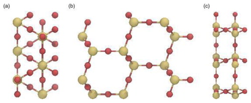
m and has two formula units per primitive unit cell [Citation60–63]. In the present work, the rectangular β-cristobalite block is generated with edge lengths that are individually adjustable within step widths of 0.506, 0.877 and 1.240 nm in x-, y-, and z-direction, respectively, corresponding to the size of the translationally invariant building block used (see ), which consists of 12 Si and 24 O atoms. Note that this minimal building block does not correspond to the cubic unit cell of β-cristobalite containing 8
groups, because for reasons outlined in Section 3 the (111) face was selected as exterior pore surface in the present work.
Figure 1. (Colour online) Building block of β-cristobalite viewed (a) from the xy-plane, (b) from the zy-plane and (c) from the xz-plane. Si and O atoms are coloured yellow and red, respectively.
Using the main pattern class as a container, child classes can be created to build other crystal lattices. Utilising the shape class, individual geometrical shapes such as cylinder or sphere can be defined to be carved out from the generated β-cristobalite block. For defining new shape classes, it is required to determine and implement the mathematical function defining the intended geometrical shape. This function will be used to determine the vector perpendicular to any point on the surface by calculating the cross product of the partial derivative of the surface function. For example, the surface function Φ of a cylinder of fixed radius r is given by
(2)
(2) Thus, the normal vector is obtained from
(3)
(3) These normal vectors will be used for surface functionalisation. The position of the centre of geometry as well as the orientation of the geometrical object with respect to the x-, y-, and z-directions can be freely defined, which enables different drill directions. As of this version, only basic geometrical shapes, such as cylinder, sphere, and cuboid are implemented. These predefined shapes can be combined to create an individual shape. Once defined, the shape is carved out of the lattice by removing all atoms within its bounds.
The atom removal generates unsaturated Si and O atoms, resulting in chemically flawed pore surfaces. Reconstruction of the surface chemistry follows the rules of Coasne et al. [Citation46]. First unsaturated Si atoms are removed. Additionally, Si atoms bonded to three dangling O atoms are removed (together with the three O atoms) as they rarely exist on silica surfaces [Citation33,Citation64,Citation65]. Depending on the drill direction the surface reconstruction leads to different values of the surface roughness and circularity of the resulting pore. The resulting surface has fully saturated Si atoms with a maximum of two unsaturated O bonds, which will be used as binding sites to attach ligands to the surface. The computational effort related to this process is determined by multiple atom–atom searches for n atoms with an algorithmic expense of .
The implemented algorithm splits the whole system into smaller, monosized cubes containing intersecting atoms. A scan for the bonds of an atom is then performed solely in the cube containing the atom and its immediate neighbour cubes, that is, in 27 cubes. Due to fixed bond lengths in the lattice, the number of atoms b in a cube is constant. The number of atom–atom searches for each cube is thus a constant with iterations. Therefore, the computational effort for an entire search scales linearly with the number of cubes C,
. Doubling the β-cristobalite block size in each direction, for example, only increases the effort eightfold compared to an unoptimised approach that would increase the effort 64 times. Furthermore, the search is easily parallelised, because no communication is needed between the subprocesses that each cover a set of cubes.
Although the search can be parallelised, multiple iterations are still required for the surface preparation. Also, it is impossible to ensure that all bonds are found when iteratively deleting atoms, because all systems are shaped differently. To overcome these issues the number of iterations was reduced to a single search of the expense of by creating a connectivity matrix of all lattice atoms prior to pore carving. The result is a dictionary that has atoms
as keys and their corresponding value is a list of bonded atoms
(4)
(4) In this implementation, pore carving is no longer associated with physically deleting atoms but with removing binding partners from the matrix. Surface preparation only considers the number of bonds remaining in each entry to determine whether an atom needs to be removed or not, which results in a computational effort scaling linearly with the number of atoms,
.
Combining all described modules, pore system classes were implemented to allow an easy generation of pore models for molecular simulations. In the package version 0.2.0, ready-to-use functions to generate cylindrical pores as well as slit pores are available.
2.2. Surface functionalisation
PoreMS generates a list of all Si atoms bonded to unsaturated O atoms with their corresponding binding partners. The reason to enumerate the Si atoms instead of the O atoms is the simplicity in determining whether the location represents a single or a geminal binding site (one or two unsaturated O atoms, respectively, connected to the Si atom) using the connectivity matrix introduced above. The connectivity matrix assumes periodic boundary conditions in each direction. If a solvent reservoir should be attached to the pore, the corresponding periodic boundary conditions are suspended. The binding sites emerging from this process prior to pore carving are designated as exterior binding sites. Binding sites generated as the result of pore carving are designated as interior binding sites.
Ligands for surface functionalisation may be constructed using the molecule builder functionality of the PoreMS package. Alternatively, an existing structure file can be used, for example in .gro or .pdb format. The recognition of other formats can be easily implemented by the user, by adding alternative interpreters to the read function of the Molecule module.
The ligand attachment is divided into multiple steps. To avoid overlap the radius of a cylinder around the main axis of the ligand (user-defined by specifying two atoms) is determined based on the Van-der-Waals radii of the atom types. Available Si binding sites within this ligand exclusion radius are found and hydroxylated to prevent future functionalisations, unless the ligand-radius is scaled to zero, thus maximising surface coverage but risking ligand–ligand overlap. The program does not check whether the chosen surface coverage is realistic; that responsibility lies with the user.
The second step is randomly choosing a Si atom from the earlier mentioned list of binding sites utilising a uniformly distributed random number generator. If the chosen binding site is already occupied, the random selection is repeated. To prevent an infinite loop, a maximal number of retries is specified, which may also be adjusted. Alternatively, instead of a random selection, a Cartesian position can be passed on to the method. In this case, the nearest unoccupied binding site will be chosen.
In case the binding site is unoccupied, the ligand is rotated so that its main axis and the normal vector of the surface (determined by the derivative of the surface function at the geometrical position of the Si atom) are aligned. The exterior surface is handled similar to the interior surface. At the planar exterior surface, the normal vector is simply the vector perpendicular to and pointing away from the surface. In case the chosen Si atom represents a geminal binding site no further functional group can be added. This is how the program ensures that double occupancy of the same Si atom by ligands is impossible even with the overlap function turned off. The Si and O atoms of the binding site are replaced by the respective atoms from the ligand. In this way, the intramolecular force field terms governing the connection of the ligand to the frozen lattice atoms can be individually customised for each ligand type. Consequently, ligand topologies have to be provided for a single and a geminal binding site. The remaining dangling O atom of an occupied geminal binding site is saturated with an H atom. In case the mentioned overlap functionality is enabled, binding sites within the proximity of the now occupied one are recursively saturated with H atoms. Because the OH group is not treated as frozen in the simulations, the same procedure as for ligands is carried out, that is, lattice Si–O or O–Si–O units are replaced with single (Si–O–H) or geminal (H–O–Si–O–H) silanol groups, respectively, and assigned a specific residue name, such that they can be distinguished from the fixed lattice atoms in the generated coordinate file. At the end of the user-specified surface functionalisation process, the remaining single and geminal unoccupied binding sites are replaced with single and geminal silanol groups, respectively, to neutralise the total pore charge and ensure chemical integrity of the surface.
Optionally, the surface hydroxylation can be reduced prior to surface functionalisation through siloxane bridge formation. Following a similar approach as Krishna et al. [Citation26], the program identifies Si-O-Si-O-Si arrangements from which the middle Si atom was cut out during pore carving. This arrangement exists in three variations: (1) one dangling O atom at each of the outer Si atoms; (2) two dangling O atoms at each of the outer Si atoms; (3) one and two dangling O atoms at the outer Si atoms. One dangling O atom is removed from each outer Si atom and a central O atom is then placed at the geometric mean location of the two removed O atoms. The resulting siloxane bridge has a Si-O bond length of 2.69 Å and Si-O-Si angle of 140.9, close to the median of the siloxane bond angle distribution in bulk vitreous silica [Citation66]. The bond length is larger than a typical Si-O bond due to the prescribed lattice positions of Si atoms in the β-cristobalite structure, whose distance is 5.07 Å. The exact representation of siloxane groups is, however, of minor importance for pore models where the silica surface is covered with relatively bulky functional groups. Reduction of surface hydroxylation is controlled by the user, whereby the maximum number of siloxane bridges and thus the minimal surface hydroxylation are limited by the β-cristobalite structure and the drilling direction. The placement of siloxane bridges is handled by randomly selecting two Si atoms in accordance with the distance criterion described above. If the binding sites are geminal, they are converted to single binding sites, if the binding sites are single, they are removed from the binding site list constructed at the beginning. Because the program package is built for maximal individualisation, siloxane bridges can be introduced at any step of pore model generation. It is, however, advisable to execute this step prior to ligand attachment, because finding two unoccupied binding sites fulfilling the distance criterion is less probable once ligands are attached to the surface.
If a reservoir is used, the size of the simulation box is adapted accordingly. The size of the reservoir is measured from the outermost atoms of the functional groups attached to the exterior surface. The Cartesian coordinates of the final pore are provided in .gro and .pdb format, respectively. An extension to other formats by the user is easily possible, by defining additional output functions in the Store module.
2.3. Force field parameters
To use the generated pores in actual molecular simulations, force-field parameters have to be provided by the user. If, for example, GROMACS is used as MD engine, itp files have to be defined for every species. The molecules may be parametrised externally (for uncommon ligands such as organometallic catalysts) or with the molecule builder that is part of PoreMS. The latter generates job files for the Antechamber topology builder [Citation67]. Only for Si, O and H atoms belonging to the silica lattice or the surface silanol groups, respectively, the force-field parameters are provided by PoreMS and are taken from the work of Gulmen and Thompson [Citation68]. Alternative force-field parameters [Citation69] may then be assigned on the topology level. The compatibility of force-field parameters for different functional groups has to be ensured by the user.
3. Results and discussion
3.1. Pore model for reversed-phase liquid chromatography
A pore model for high-performance liquid chromatography aims to replicate the conditions inside a chromatographic column. The column is a fixed bed containing two types of pores, macropores for advective (flow-driven) transport and mesopores for diffusive transport. This type of architecture is realised by dense packings of μm-sized, mesoporous, spherical silica particles or by macroporous silica monoliths with mesoporous skeletons. Silica particles are functionalised before being packed into a column, whereas silica monoliths are fully formed prior to surface functionalisation. In reversed-phase liquid chromatography (RPLC), the most widely used separation mode today, compounds of low-to-moderate polarity are separated between a hydrophobic stationary phase and an aqueous–organic mobile phase. The stationary phase is the silica structure bearing the bonded phase, which consists of the main ligand and eventually endcapping groups. RPLC ligands are typically unbranched alkyl chains of defined length. The ligands are covalently attached to reactive groups at the silica surface, which are present inside the mesopores as well as at the outside of a silica particle or skeleton. Consequently, ligands line the macropores as well as the mesopores. Surface functionalisation with the main ligand is usually followed by endcapping, a process in which short, voluminous, hydrophobic groups are attached to previously unreacted surface OH groups to reduce as well as shield the residual hydroxylation of the silica surface. Compounds are separated according to their differential interaction with the chromatographic interface, which forms when the column is equilibrated with the liquid mobile phase prior to sample injection. At the instrumental level, column equilibration refers to pumping the mobile phase through the column until the composition of the effluent liquid matches the composition of the influent liquid. At the molecular level, column equilibration refers to the interaction between the stationary phase and the solvent molecules of the mobile phase. Solvent molecules penetrate the bonded phase, solvating the ligands, and coordinate the residual OH groups of the silica surface. The most important process occurring during column equilibration in RPLC is the formation of an organic-solvent rich layer at the interface between the alkyl chain ends and the bulk mobile phase. This layer forms a transition between the hydrophobic ligands and the aqueous–organic fluid that strives to preserve its hydrogen-bonding structure.
In the pore model, the two surfaces of the silica block perpendicular to the pore axis and facing the solvent reservoirs represent the exterior of a mesoporous particle or skeleton. At the nm-scale of the cylindrical pore, the exterior of the μm-sized particle or skeleton is approximately flat. Relevant chemical parameters to replicate an RPLC mesopore are the ligand chemistry, which comprises the chemical structure of the ligand and the type of bonding to the silica surface, the ligand density, presence and extent of endcapping, the chemistry of the underlying silica surface and its degree of residual hydroxylation, and the pore diameter. The generated pore model () targets an average commercial RPLC column for the separation of low-molecular-weight compounds. Such a column typically features dimethyloctadecylsilyl (C) chains attached via a single bond to the silica surface at a ligand density of
plus endcapping with trimethylsilyl (TMS) groups at an overall bonded-phase coverage of
. Chromatographic silica is amorphous with an average surface hydroxylation of 7–8
before functionalisation and a residual surface hydroxylation of
after functionalisation and endcapping. The surface chemistry comprises OH groups in form of single (isolated or vicinal) and geminal silanols as well as siloxane bridges. Chromatographic silica is known for its disordered pore structure and wide pore size distribution. Average pore diameters of 9–10 nm are fairly standard for RPLC columns intended for small molecules [Citation22,Citation23].
Figure 2. (Colour online) Cylindrical RPLC mesopore model generated with PoreMS using the input parameters given in . (a) Side view of the simulation box indicating the length of the central silica block and the solvent reservoirs. (b) and (c) Front and side view, respectively, of the pierced silica block containing the 9 nm diameter pore. The chemistry of the exterior surface is based on the (111) face of β-cristobalite silica. Exterior planar and interior curved surface are covered with the bonded phase consisting of C chains as the main ligand and TMS groups for endcapping. Bonded-phase groups are randomly distributed on the silica surface. Ligand and endcapping densities, residual surface hydroxylation, and further details are specified in . Colour code: Si, yellow lines; O, red lines; C
chains, blue; TMS groups, magenta; residual surface silanol groups, yellow.
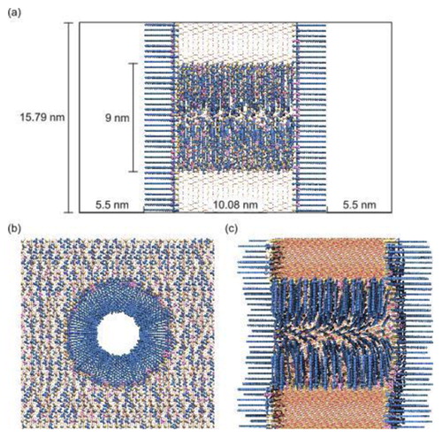
Table 1. Input parameters used to generate the RPLC mesopore model.
Table 2. Properties of the generated cylindrical RPLC mesopore model.
Figure shows the cylindrical RPLC mesopore model generated with PoreMS using parameters to replicate the conditions inside a standard RPLC column as outlined above. The input parameters are given in , the properties of the generated pore model are listed in detail in . The first set of parameters concerns the dimensions of the silica block, the targeted pore diameter, the drilling direction, and the length of the solvent reservoirs at each side of the silica block. The dimensions of the silica block were chosen to obtain sufficiently large interior and exterior pore surface areas required to produce good statistics for analysing density, structure, and dynamics of solvent and solute molecules at the liquid–solid interface inside the mesopore (curved) or at the particle outside (planar). The pore diameter was set to 9 nm and the drilling direction was chosen along the z-axis so that the (111) face of β-cristobalite SiO, which owing to its surface hydroxylation has become the standard model for chromatographic silica surfaces [Citation10,Citation33], faces the solvent reservoirs. The choice of drilling direction determines the maximal surface hydroxylation and thus provides options to realise different combinations of ligand density, endcapping, and residual hydroxylation on the pore surfaces. Incidentally, drilling along the z-direction also produces the smoothest interior surface (minimal surface roughness). However, the effects are rather weak. In a 3 nm cylindrical pore, the surface roughness is 0.11, 0.07, and 0.08 nm, when drilling in x-, y-, and z-direction, respectively, and the maximum possible surface hydroxylation is 9.12, 9.35, and 8.83
. In a 9 nm cylindrical pore, the surface roughness is 0.11, 0.09, and 0.08 nm and the maximum possible surface hydroxylation is 9.50, 9.75, and 9.24
. The equations used to calculate these properties are reported in the Appendix. The solvent reservoirs need to be long enough to observe and sample a statistically relevant stretch of bulk behaviour of the liquid mobile phase, that is, the extension of the organic-solvent rich layer has to be taken into account. The specific length required depends on the system studied (the properties of the functionalised silica as well as of the solvent mixture). The solvent reservoir length chosen for this example was informed by prior MD simulation studies using a slit-pore model of
functionalised silica equilibrated with water–acetonitrile mixtures [Citation24,Citation25]. The chosen length should suffice for modelling bonded phases of similar or shorter chain length than C
and common aqueous–organic mobile phases.
The second set of parameters concerns the functionalisation and hydroxylation of the silica surface. The chosen drilling direction dictates that the exterior surface bears mostly single silanols; the rare geminal silanols are located at the rim to the pore entrance. Pore carving yields an interior surface with a higher percentage of geminal silanols than found outside. Consequently, the interior surface hydroxylation after carving is higher than at the exterior surface. The user has different options to arrive at a comparable residual hydroxylation of the interior and exterior surface while maintaining an identical main ligand density inside and outside: (i) increase the inside endcapping density to reach an identical bonded-phase coverage inside and outside and thus an identical residual surface hydroxylation, (ii) reduce the interior surface hydroxylation prior to surface functionalisation through siloxane bridge building, and (iii) use a combination of siloxane bridge building and endcapping density increase. In the present example, we selected the second option and introduced siloxane bridges on the interior surface to match its hydroxylation to that of the exterior surface after carving (7.82 ). For the bonded phase, we chose C
as the main ligand at a density of 2.91
and aimed for an overall coverage of 46% with respect to the total number of OH groups. These values translate to an endcapping density of 0.70–0.71
and a residual surface hydroxylation of 4.20–4.21
. Generation of the cylindrical RPLC mesopore model took 33.5 s on eight cores.
3.2. Pore model for molecular heterogeneous catalysis
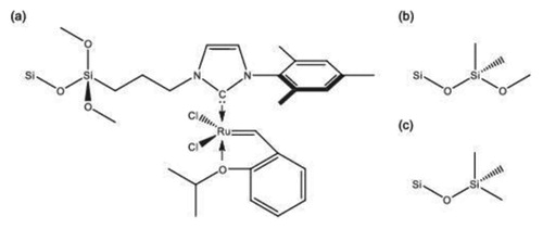
The pore model to study confinement effects in molecular heterogeneous catalysis aims to capture the size, the dominant geometry (cylinder), and the surface chemistry of typical ordered mesoporous silica materials, such as MCM [Citation70] or SBA silica [Citation36,Citation71]. The pore model targets the experimental concept of pore-size selective immobilisation of a well-defined organometallic catalyst present on the interior, but not the exterior surface of a pore, as used recently to study olefin metathesis in confined geometries [Citation17]. Experimentally, this selective immobilisation is achieved in a multi-step process, in which the interior pore surface is blocked by filling the mesopores with a polymer, then the exterior particle surface passivated by endcapping with TMS groups, and finally the interior pore surface unblocked again through polymer removal by Soxhlet extraction with ethanol [Citation17,Citation72]. This procedure forces the catalyst to attach to the interior pore surface, as reactive groups at the particle outside are unavailable or inaccessible. Optionally, the interior pore surface can be further modified with dimethoxydimethylsilyl (DMDMS) groups to decrease the surface polarity and thus the polarity difference at the solid–liquid interface for working with the apolar solvents used in heterogeneous catalysis, such as benzene in the present example. Coverage of the interior pore surface with DMDMS groups also prevents that substrate and product molecules with polar groups can form hydrogen bonds to residual surface OH groups, which would lead to the enrichment of substrate and product molecules at the silica surface. Local enrichment close to the catalytic centre is highly undesirable as it carries the risk of oligomerisation (substrate) and ring opening (product). The chemical structures of the three surface functionalisations are shown in .
Figure 3. Functionalisation at the interior (a,b) and exterior surface (c) of the generated cylindrical silica pore model for heterogeneous catalysis. (a) Ruthenium catalyst, (b) dimethoxydimethylsilyl (DMDMS) group, (c) trimethylsilyl (TMS) group.
shows the cylindrical catalytic pore model of 4.8 nm diameter, generated with PoreMS using the parameters to replicate previous work [Citation17]. The input parameters are given in , the properties of the generated pore model are listed in detail in . Contrary to the RPLC pore model, siloxane bridges were not introduced to the catalytic pore model. Endcapping with TMS groups were applied to the exterior surface, while the interior surface was functionalised with DMDMS groups. Additionally, two Ru-based catalyst groups were attached to the interior surface in point symmetry with respect to the centre of geometry of the pore. The hydroxylation of the interior surface prior to functionalisation (8.84 ) recovers typical values assigned to amorphous silica [Citation63–65]. One goal of functionalisation was to create a largely apolar surface. The bulky DMDMS groups attached at a density of 5.54
effectively screen the residual OH groups on the silica surface (3.29
) from access by solvent or solute molecules. The same effect is obtained on the exterior surface covered by TMS groups at a density of 4.47
, resulting in a residual hydroxylation of 3.91
. The catalyst density of 0.02
was chosen 4 to 5 times higher than in the experiment [Citation17] to improve the statistical sampling in the simulation. In the experiment, a lower catalyst density was used to guard against interaction between reacting substrate molecules close to a catalyst group as well as between the catalyst groups themselves, as contrary to the pore model, a uniform spatial distribution could not be guaranteed. Generation of the cylindrical catalytic mesopore model took 8.2 s on eight cores.
Figure 4. (Colour online) Cylindrical catalytic mesopore model generated with PoreMS using the input parameters given in . (a) Side view of the simulation box indicating the length of the central silica block and the solvent reservoirs. (b) and (c) Front and side view, respectively, of the pierced silica block containing the 4.8 nm pore. The chemistry of the exterior surface is based on the (111) face of β-cristobalite silica. The exterior planar and interior curved surfaces are covered with randomly distributed TMS and DMDMS groups, respectively. Two organometallic catalyst groups are attached to the interior surface in point symmetry with respect to the pore centre. The densities of all surface groups and further details are specified in . Colour code: Si atoms, yellow line; O atoms, red line; DMDMS groups, blue; TMS groups, magenta; catalyst, purple; residual surface silanol groups, yellow.
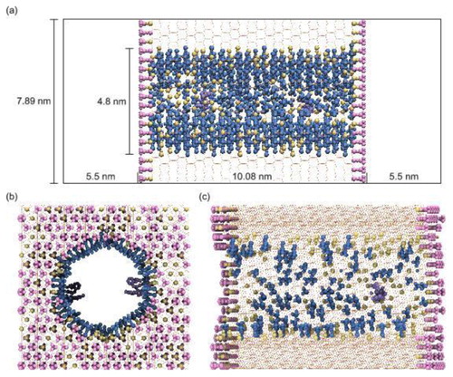
Table 3. Input parameters used to generate the catalytic mesopore model.
Table 4. Properties of the generated cylindrical catalytic mesopore model.
4. Conclusion and outlook
We introduced the open source software tool PoreMS to facilitate rapid model building of functionalised silica pores for Monte Carlo or molecular dynamics simulation studies of confinement effects in applications relying on functionalised mesoporous silica. The capability of PoreMS was demonstrated by the generation of explicit cylindrical pore models for reversed-phase liquid chromatography and molecular heterogeneous catalysis. In experimental practice, the actual surface chemistry of functionalised mesoporous silica depends on various aspects of the sample preparation and its details are not known with high accuracy. Therefore, we designed a modular program structure that allows high flexibility in carrying out different steps of the pore generation as well as individual customisation of ligands. Moreover, the short generation time of a few seconds allows for an iterative fine-tuning towards a pore model that is both computationally tractable and representative of a targeted surface chemistry. The introduction of PoreMS should stimulate systematic molecular simulations research on confinement effects in functionalised cylindrical silica pores, as at present experimental advances relying on functionalised mesoporous silica materials are still largely empirically driven due to the lack of molecular-level information. Further development of PoreMS could address the implementation of alternative bulk silica structures.
Supplemental Material
Download Zip (11.1 KB)Acknowledgments
This work was funded by the Deutsche Forschungsgemeinschaft (DFG, German Research Foundation), project ID 358283783 -- SFB 1333 (N.H.) and grant TA 268/11-1 (U.T.), by the Ministry of Science, Research and Arts, and the Universities of the State of Baden-Württemberg, Germany (N.H.), and by the Federal Ministry of Education and Research of Germany under project number 16FDM008 (N.H.).
Disclosure statement
No potential conflict of interest was reported by the authors.
Additional information
Funding
References
- Margelefsky EL, Zeidan RK, Davis ME. Cooperative catalysis by silica-supported organic functional groups. Chem Soc Rev. 2008;37(6):1118–1126. Available from: http://xlink.rsc.org/?DOI=b710334b.
- Marras F, Wang J, Coppens MO, et al. Ordered mesoporous materials as solid supports for rhodium–diphosphine catalysts with remarkable hydroformylation activity. Chem Commun. 2010;46(35):6587–6589. Available from: http://xlink.rsc.org/?DOI=c0cc00924e.
- ALOthman Z. A review: fundamental aspects of silicate mesoporous materials. Materials. 2012;5(12):2874–2902. Available from: http://www.mdpi.com/1996-1944/5/12/2874.
- Narayan R, Nayak U, Raichur A, et al. Mesoporous silica nanoparticles: a comprehensive review on synthesis and recent advances. Pharmaceutics. 2018;10(3):118. Available from: http://www.mdpi.com/1999-4923/10/3/118.
- Diagboya PN, Dikio ED. Silica-based mesoporous materials; emerging designer adsorbents for aqueous pollutants removal and water treatment. Microporous Mesoporous Mater. 2018;266:252–267. Available from: https://linkinghub.elsevier.com/retrieve/pii/S138718111830132X.
- Molaei S, Tamoradi T, Ghadermazi M, et al. Highly efficient oxidative coupling of thiols and oxidation of sulfides in the presence of MCM-41@tryptophan-Cd and MCM-41@tryptophan-Hg as novel and recoverable nanocatalysts. Catal Lett. 2018;148(7):1834–1847. Available from: http://link.springer.com/10.1007/s10562-018-2379-3.
- Siefker J, Biehl R, Kruteva M, et al. Confinement facilitated protein stabilization as investigated by small-angle neutron scattering. J Am Chem Soc. 2018;140(40):12720–12723. Available from: https://pubs.acs.org/doi/10.1021/jacs.8b08454.
- Dong B, Mansour N, Pei Y, et al. Single molecule investigation of nanoconfinement hydrophobicity in heterogeneous catalysis. J Am Chem Soc. 2020;142(31):13305–13309. Available from: https://pubs.acs.org/doi/10.1021/jacs.0c05905.
- Melnikov SM, Höltzel A, Seidel-Morgenstern A, et al. Composition, structure, and mobility of water–acetonitrile mixtures in a silica nanopore studied by molecular dynamics simulations. Anal Chem. 2011;83(7):2569–2575. Available from: https://pubs.acs.org/doi/10.1021/ac102847m.
- Lindsey RK, Rafferty JL, Eggimann BL, et al. Molecular simulation studies of reversed-phase liquid chromatography. J Chromatogr A. 2013;1287:60–82. Available from: https://linkinghub.elsevier.com/retrieve/pii/S0021967313003294.
- Melnikov SM, Höltzel A, Seidel-Morgenstern A, et al. A molecular dynamics study on the partitioning mechanism in hydrophilic interaction chromatography. Angew Chem Int Ed. 2012;51(25):6251–6254. Available from: http://doi.wiley.com/10.1002/anie.201201096.
- Melnikov SM, Höltzel A, Seidel-Morgenstern A, et al. A molecular dynamics view on hydrophilic interaction chromatography with polar-bonded phases: properties of the water-rich layer at a silica surface modified with diol-functionalized alkyl chains. J Phys Chem C. 2016;120(24):13126–13138. Available from: https://pubs.acs.org/doi/10.1021/acs.jpcc.6b03799.
- Rybka J, Höltzel A, Melnikov SM, et al. A new view on surface diffusion from molecular dynamics simulations of solute mobility at chromatographic interfaces. Fluid Phase Equilib. 2016;407:177–187. Available from: https://linkinghub.elsevier.com/retrieve/pii/S0378381215003015.
- Rybka J, Höltzel A, Tallarek U. Surface diffusion of aromatic hydrocarbon analytes in reversed-phase liquid chromatography. J Phys Chem C. 2017;121(33):17907–17920. Available from: https://pubs.acs.org/doi/10.1021/acs.jpcc.7b04746.
- El Hage K, Gupta PK, Bemish R, et al. Molecular mechanisms underlying solute retention at heterogeneous interfaces. J Phys Chem Lett. 2017;8(18):4600–4607. Available from: https://pubs.acs.org/doi/10.1021/acs.jpclett.7b01966.
- El Hage K, Bemish RJ, Meuwly M. From in silica to in silico: retention thermodynamics at solid–liquid interfaces. Phys Chem Chem Phys. 2018;20(27):18610–18622. Available from: http://xlink.rsc.org/?DOI=C8CP02899K.
- Ziegler F, Teske J, Elser I, et al. Olefin metathesis in confined geometries: a biomimetic approach toward selective macrocyclization. J Am Chem Soc. 2019;141(48):19014–19022. Available from: https://pubs.acs.org/doi/10.1021/jacs.9b08776.
- Zheng W, Yamada SA, Hung ST, et al. Enhanced Menshutkin S n2 reactivity in mesoporous silica: the influence of surface catalysis and confinement. J Am Chem Soc. 2020;142(12):5636–5648. Available from: https://pubs.acs.org/doi/10.1021/jacs.9b12666.
- Kobayashi T, Kraus H, Hansen N, et al. Confined Ru-catalysts in a two phase heptane/ionic liquid solution: modeling aspects. Chem Cat Chem. 2020. Available from: https://doi.org/10.1002/cctc.202001596.
- Nejad MA, Urbassek HM. Diffusion of cisplatin molecules in silica nanopores: molecular dynamics study of a targeted drug delivery system. J Mol Graph Model. 2019;86:228–234. Available from: https://linkinghub.elsevier.com/retrieve/pii/S1093326318304376.
- Bruix A, Margraf JT, Andersen M, et al. First-principles-based multiscale modelling of heterogeneous catalysis. Nature Catalysis. 2019;2(8):659–670. Available from: http://www.nature.com/articles/s41929-019-0298-3.
- Žuvela P, Skoczylas M, Jay Liu J, et al. Column characterization and selection systems in reversed-phase high-performance liquid chromatography. Chem Rev. 2019;119(6):3674–3729. Available from: https://pubs.acs.org/doi/10.1021/acs.chemrev.8b00246.
- Žuvela P, Skoczylas M, Liu JJ, et al. Addition: column characterization and selection systems in reversed-phase high-performance liquid chromatography. Chem Rev. 2019;119(7):4818–4818. Available from: https://pubs.acs.org/doi/10.1021/acs.chemrev.9b00167.
- Rybka J, Höltzel A, Steinhoff A, et al. Molecular dynamics study of the relation between analyte retention and surface diffusion in reversed-phase liquid chromatography. J Phys Chem C. 2019;123(6):3672–3681. Available from: https://pubs.acs.org/doi/10.1021/acs.jpcc.8b11983.
- Rybka J, Höltzel A, Trebel N, et al. Stationary-phase contributions to surface diffusion in reversed-phase liquid chromatography: chain length versus ligand density. J Phys Chem C. 2019;123(35):21617–21628. Available from: https://pubs.acs.org/doi/10.1021/acs.jpcc.9b06160.
- Krishna R. Describing the diffusion of guest molecules inside porous structures. J Phys Chem C. 2009;113(46):19756–19781. Available from: https://pubs.acs.org/doi/10.1021/jp906879d.
- Brkljča Z, Klimczak M, Miličević Z, et al. Complementary molecular dynamics and X-ray reflectivity study of an imidazolium-based ionic liquid at a neutral sapphire interface. J Phys Chem Lett. 2015;6(3):549–555. Available from: https://pubs.acs.org/doi/10.1021/jz5024493.
- Stepić R, Wick CR, Strobel V, et al. Mechanism of the water–gas shift reaction catalyzed by efficient ruthenium–based catalysts: a computational and experimental study. Angew Chem Int Ed. 2019;58(3):741–745. Available from: https://onlinelibrary.wiley.com/doi/abs/10.1002/anie.201811627.
- Vučemilović-Alagić N, Banhatti RD, Stepić R, et al. Insights from molecular dynamics simulations on structural organization and diffusive dynamics of an ionic liquid at solid and vacuum interfaces. J Colloid Interface Sci. 2019;553:350–363. Available from: https://linkinghub.elsevier.com/retrieve/pii/S0021979719306903.
- García A, Slowing II, Evans JW. Pore diameter dependence of catalytic activity: p-nitrobenzaldehyde conversion to an aldol product in amine-functionalized mesoporous silica. J Chem Phys. 2018;149(2):024101. Available from: http://aip.scitation.org/doi/10.1063/1.5037618.
- Apostolopoulou M, Santos MS, Hamza M, et al. Quantifying pore width effects on diffusivity via a novel 3D stochastic approach with input from atomistic molecular dynamics simulations. J Chem Theory Comput. 2019;15(12):6907–6922. Available from: https://pubs.acs.org/doi/10.1021/acs.jctc.9b00776.
- Tallarek U, Hlushkou D, Rybka J, et al. Multiscale simulation of diffusion in porous media: from interfacial dynamics to hierarchical porosity. J Phys Chem C. 2019;123(24):15099–15112. Available from: https://pubs.acs.org/doi/10.1021/acs.jpcc.9b03250.
- Zhuravlev L. The surface chemistry of amorphous silica. Zhuravlev model. Colloids Surf A. 2000;173(1–3):1–38. Available from: https://linkinghub.elsevier.com/retrieve/pii/S0927775700005562.
- Melnikov SM, Höltzel A, Seidel-Morgenstern A, et al. How ternary mobile phases allow tuning of analyte retention in hydrophilic interaction liquid chromatography. Anal Chem. 2013;85(18):8850–8856. Available from: https://pubs.acs.org/doi/10.1021/ac402123a.
- Beck JS, Vartuli JC, Roth WJ, et al. A new family of mesoporous molecular sieves prepared with liquid crystal templates. J Am Chem Soc. 1992;114:10834–10843. Available from: https://doi.org/10.1021/ja00053a020.
- Zhao D, Feng J, Huo Q, et al. Triblock copolymer syntheses of mesoporous silica with periodic 50 to 300 Angstrom pores. Science. 1998;279:548–552. Available from: https://www.sciencemag.org/lookup/doi/10.1126/science.279.5350.548.
- Kleitz F, Choi SH, Ryoo R. Cubic Ia3d large mesoporous silica: synthesis and replication to platinum nanowires, carbon nanorods and carbon nanotubes. Chem Commun. 2003;17:2136–2137. Available from: https://doi.org/10.1039/B306504A.
- Reich SJ, Svidrytski A, Hlushkou D, et al. Hindrance factor expression for diffusion in random mesoporous adsorbents obtained from pore-scale simulations in physical reconstructions. Ind Eng Chem Res. 2018;57(8):3031–3042. Available from: https://pubs.acs.org/doi/10.1021/acs.iecr.7b04840.
- Reich SJ, Svidrytski A, Höltzel A, et al. Hindered diffusion in ordered mesoporous silicas: insights from pore-scale simulations in physical reconstructions of SBA-15 and KIT-6 silica. J Phys Chem C. 2018;122(23):12350–12361. Available from: https://pubs.acs.org/doi/10.1021/acs.jpcc.8b03630.
- Rafferty JL, Siepmann J, Schure M. The effects of chain length, embedded polar groups, pressure, and pore shape on structure and retention in reversed-phase liquid chromatography: molecular-level insights from Monte Carlo simulations. J Chromatogr A. 2009;1216(12):2320–2331. Available from: https://linkinghub.elsevier.com/retrieve/pii/S0021967309000107.
- Melnikov SM, Höltzel A, Seidel-Morgenstern A, et al. Adsorption of water–acetonitrile mixtures to model silica surfaces. J Phys Chem C. 2013;117(13):6620–6631. Available from: https://pubs.acs.org/doi/10.1021/jp312501b.
- Williams JJ, Wiersum AD, Seaton NA, et al. Effect of surface group functionalization on the CO 2/N 2 separation properties of MCM-41: a grand-canonical Monte Carlo simulation study. J Phys Chem C. 2010;114(43):18538–18547. Available from: https://pubs.acs.org/doi/10.1021/jp105464u.
- Williams JJ, Seaton NA, Düren T. Influence of surface groups on the diffusion of gases in MCM-41: a molecular dynamics study. J Phys Chem C. 2011;115(21):10651–10660. Available from: https://pubs.acs.org/doi/10.1021/jp112073z.
- Lowry E, Piri M. Effect of surface chemistry on confined phase behavior in nanoporous media: an experimental and molecular modeling study. Langmuir. 2018;34(32):9349–9358. Available from: https://pubs.acs.org/doi/10.1021/acs.langmuir.8b00986.
- Elola MD, Rodriguez J. Ionic mobility within functionalized silica nanopores. J Phys Chem C. 2019;123(6):3622–3633. Available from: https://pubs.acs.org/doi/10.1021/acs.jpcc.8b11444.
- Coasne B, Di Renzo F, Galarneau A, et al. Adsorption of simple fluid on silica surface and nanopore: effect of surface chemistry and pore shape. Langmuir. 2008;24(14):7285–7293. Available from: https://pubs.acs.org/doi/10.1021/la800567g.
- Williams CD, Travis KP, Burton NA, et al. A new method for the generation of realistic atomistic models of siliceous MCM-41. Microporous Mesoporous Mater. 2016;228:215–223. Available from: https://linkinghub.elsevier.com/retrieve/pii/S1387181116300609.
- Geske J, Vogel M. Creating realistic silica nanopores for molecular dynamics simulations. Mol Simul. 2017;43(1):13–18. Available from: https://www.tandfonline.com/doi/full/10.1080/08927022.2016.1221072.
- Keen DA, McGreevy RL. Structural modeling of glasses using reverse Monte-Carlo simulation. Nature. 1990;344:423–425. Available from: https://www.nature.com/articles/344423a0.
- Siperstein FR, Gubbins KE. Synthesis and characterization of templated mesoporous materials using molecular simulation. Mol Simul. 2001;27:339–352. Available from: https://www.tandfonline.com/doi/abs/10.1080/08927020108031357.
- Coasne B, Hung FR, Pellenq RJM, et al. Adsorption of simple gases in MCM-41 materials: the role of surface roughness. Langmuir. 2006;22):194–202. Available from: https://pubs.acs.org/doi/abs/10.1021/la051676g.
- Bhattacharya S, Coasne B, Hung FR, et al. Modeling micelle-templated mesoporous material SBA-15: atomistic model and gas adsorption studies. Langmuir. 2009;25:5802–5813. Available from: https://pubs.acs.org/doi/10.1021/la801560e.
- Schumacher C, Gonzalez J, Wright PA, et al. Generation of atomistic models of periodic mesoporous silica by kinetic Monte Carlo simulation of the synthesis of the material. J Phys Chem B. 2006;110(1):319–333. Available from: https://pubs.acs.org/doi/10.1021/jp0551871.
- Ferreiro-Rangel CA, Lozinska MM, Wright PA, et al. Kinetic Monte Carlo simulation of the synthesis of periodic mesoporous silicas SBA-2 and STAC-1: generation of realistic atomistic models. J Phys Chem C. 2012;116:20966–20974. Available from: https://pubs.acs.org/doi/abs/10.1021/jp307610a.
- Jorge M, Milne AW, Sobek ON, et al. Modelling the self-assembly of silica-based mesoporous materials. Mol Simul. 2018;44:435–452. Available from: https://www.tandfonline.com/doi/abs/10.1080/08927022.2018.1427237.
- Han Y, Slowing II, Evans JW. Surface structure of linear nanopores in amorphous silica: comparison of properties for different pore generation algorithms. J Chem Phys. 2020;153:124708. Available from: https://aip.scitation.org/doi/abs/10.1063/5.0021317?journalCode=jcp.
- Thompson MW, Gilmer JB, Matsumoto RA, et al. Towards molecular simulations that are transparent, reproducible, usable by others, and extensible (TRUE). Mol Phys. 2020;118:e1742938. Available from: https://www.tandfonline.com/doi/full/10.1080/00268976.2020.1742938.
- Abraham MJ, Murtola T, Schulz R, et al. GROMACS: high performance molecular simulations through multi-level parallelism from laptops to supercomputers. SoftwareX. 2015;1–2:19–25. Available from: https://linkinghub.elsevier.com/retrieve/pii/S2352711015000059.
- Kraus H, Hansen N. PoreMS: v0.2.0; 2020. Available from: https://doi.org/10.5281/zenodo.3984865.
- Wyckoff RWG. Crystal structure of high temperature cristobalite. Am J Sci. 1925;s5-9(54):448–459. Available from: http://www.ajsonline.org/cgi/doi/10.2475/ajs.s5-9.54.448.
- Wyckoff RWG. Die Kristallstruktur von β-Cristobalit (bei hohen Temperaturen stabile Form). Z Kristallogr. 1925;62(1–6):189–200. Available from: http://www.degruyter.com/view/j/zkri.1925.62.issue-1-6/zkri.1925.62.1.189/zkri.1925.62.1.189.xml.
- Peacor DR. High-temperature single-crystal study of the cristobalite inversion. Z Kristallogr. 1973;138(1–4):274–298. Available from: http://www.degruyter.com/doi/10.1524/zkri.1973.138.1-4.274.
- Villars P, Calvert LD. Pearson's handbook of crystallographic data for intermetallic phases. 2nd ed. Materials Park (OH): ASM International; 1991.
- Unger KK. Porous silica, its properties and use as support in column liquid chromatography. Amsterdam: Elsevier; 1979. (Journal of chromatography library; v. 16).
- Vansant EF, Van Der Voort P, Vrancken KC. Characterization and chemical modification of the silica surface. Amsterdam: Elsevier; 1995. (Studies in surface science and catalysis; v. 93).
- Litton DA, Garofalini SH. Modeling of hydrophilic wafer bonding by molecular dynamics simulations. J Appl Phys. 2001;89(11):6013–6023. Available from: http://aip.scitation.org/doi/10.1063/1.1351538.
- Wang J, Wang W, Kollman PA, et al. Automatic atom type and bond type perception in molecular mechanical calculations. J Mol Graph Model. 2006;25(2):247–260. Available from: https://linkinghub.elsevier.com/retrieve/pii/S1093326305001737.
- Gulmen TS, Thompson WH. Testing a two-state model of nanoconfined liquids: conformational equilibrium of ethylene glycol in amorphous silica pores. Langmuir. 2006;22(26):10919–10923. Available from: https://pubs.acs.org/doi/10.1021/la062285k.
- Abramov A, Iglauer S. Application of the CLAYFF and the DREIDING force fields for modeling of alkylated quartz surfaces. Langmuir. 2019;35(17):5746–5752. Available from: https://pubs.acs.org/doi/10.1021/acs.langmuir.9b00527.
- Zhao XS, Lu GQ, Whittaker AK, et al. Comprehensive study of surface chemistry of MCM-41 using 29Si CP/MAS NMR, FTIR, pyridine-TPD, and TGA. J Phys Chem B. 1997;101(33):6525–6531. Available from: https://doi.org/10.1021/jp971366+.
- Soler-Illia GJA, Crepaldi EL, Grosso D, et al. Block copolymer-templated mesoporous oxides. Curr Opin Colloid Interface Sci. 2003;8(1):109–126. Available from: https://linkinghub.elsevier.com/retrieve/pii/S1359029403000025.
- Webb JD, Seki T, Goldston JF, et al. Selective functionalization of the mesopores of SBA-15. Microporous Mesoporous Mater. 2015;203:123–131. Available from: https://linkinghub.elsevier.com/retrieve/pii/S138718111400612X.
Appendix
The pore diameter is obtained as
(A1)
(A1) where
denotes the shortest distance between a surface Si atom
and the central axis of the pore. The pore surface roughness is calculated as standard deviation of these distances,
(A2)
(A2) The interior pore volume is calculated as
(A3)
(A3) where l denotes the length of the pore. The interior surface area is obtained from
(A4)
(A4) while the exterior surface is calculated as
(A5)
(A5) where x and y denote the dimensions of the silica block in the respective directions.