
ABSTRACT
This research introduces a new share design (L-share) that reduces the undesired random soil movement, providing a more controlled disturbance of the upper soil layer. Purpose: The aim of this study was to evaluate draught forces and soil movements when operating the new share. Materials and Methods: Experiments were conducted in a laboratory set-up using a soil bin with a fine loamy soil texture. The soil was compacted to a bulk density of 1500 kg m−3, with a penetration index of 486 kPa and a mean water content of 10%. The cultivation depths were 30, 50 and 70 mm and the operation speeds were 0.84, 1.67 and 2.31 m s−1. Cubes were used to measure soil movement by recording the displacement from their initial positions. The soil surface and furrow profile were measured by using a 2D laser range scanner. Results: The results showed that increasing operation speed and cultivation depths generally increased draught forces and soil movement. Changing the cultivation depth from 30 to 50 mm resulted in a 63% greater longitudinal force (Fx), and 71% greater Fx when increasing the cultivation depth from 50 to 70 mm. Conclusion: The study showed that the new L-share mounted on a modified spring tine only causes minor soil movement and thereby minimising the undesirable soil movement.
Introduction
Organic crop production has increased significantly in Europe and North America in recent years, mainly due to customer demand for organic products. In Denmark, for example, demand increased by 25% from 2006 to 2007 (Husted and Bügel Citation2009). Weed management is an important component in organic crop production and both research and innovations have focused on improving mechanical weed control methods (Melander et al. Citation2005; Van Der Weide et al. Citation2008).
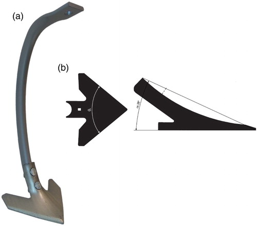
Inter-row cultivation is a fundamental method for controlling inter-row weeds in typical row crops grown at 0.25–0.7 m inter-row spacing, e.g. sugar beet and maize. The term ‘duckfoot share’ (abbreviated ‘DF-share’) covers a range of hoe share configurations that all, to some extent, resemble a duck’s foot. The DF-share () is mounted either on stiff shanks or vibrating spring-tines providing the weeding action; this set-up is found on many inter-row cultivators across the world. The DF-share is operated at shallow depths and controls weeds effectively when they are relatively small and the soil is suitable for cultivation (Melander et al. Citation2005). The DF-share can have a number of wing width dimensions in order to suit a wide range of inter-row spaces. While performing effective weed control, the DF-share may cause undesirable soil movement due to its share rake angle αs of 28–30°. The DF-share interacts with soil in two ways: first by cutting the soil layer to the maximum depth of cultivation, and second by deforming and intensely mixing the loosened soil.
Figure 1. DF-share: (a) mounted on a VTH-L/VTH-stem tine (7″ sweep produced by Kongskilde Industries A/S, Denmark), and (b) drawings showing (the clearance share angle) and
(the nose angle).
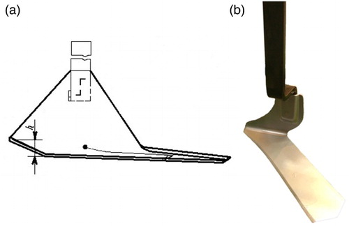
Another option for mechanical weed control is the sweep share (). The vertical part of the sweep is positioned close to the crop row, while the horizontal part points towards the middle of the inter-row space. Sweeps are mounted in pairs for each inter-row space and the sideward soil movement towards the crop row is minimal, which means the plants are not covered in soil. Sweeps control weeds at relatively late growth stages using high operation speeds (up to 3.06 m s−1). It causes little soil disturbance and appears to have great potential for controlling weeds over a wide range of row widths (Pullen and Cowell Citation1997; Alexandrou and Coffing Citation1998; Home Citation2003; Weiss et al. Citation2011).
Figure 2. Sweep: (a) drawing (h – the distance between the blade and nose of the sweep, mm) (Author’s certificate SU 1701129 A 1, 1965), and (b) image of a unit produced by Kress Umweltschonende Landtechnik GmbH (KULT), Germany (Agritechnica 2015, Hannover).
Some manufacturers offer devices where the sweep is combined with a DF-share or an arrow-flat cutting-share for inter-row cultivation, e.g. the Multioperational cultivator УСМК-5,4 (Russia). However these cultivators have a number of drawbacks. One major drawback is the badly designed parallelogram suspension system. Shares begin to oscillate during operation, which causes significant wear of the system. When the parallelogram suspension system and shares start to wear, accurate steering becomes critical and a larger safety zone around the crop row is needed to avoid crop damage. Ultimately, this will result in a larger area not being subjected to weed control.
For optimal inter-row cultivation, an inter-row cultivator needs to fulfil the following main agronomic requirements: the soil should be left with a smooth surface after cultivation with minimal ridges and furrows, and soil movements from the share to the crop row should be minimised to avoid covering the crop with too much soil. In addition, cultivation should be kept at a constant soil depth, with deviations not exceeding ± 10 mm, and the horizontal blade should control at least 98%–99% of the weeds without injuring the crop.
Current hoe shares do not meet all the above-mentioned criteria and there is therefore a need to develop better shares to optimise mechanical weed control. One particular disadvantage is that hoe shoes can cause uncontrolled throwing of soil, thereby covering plants. Poor soil structure not only adversely affects crop growth, but can also result in the regrowth of weeds after weed control, e.g. when weed roots are anchored in strong soil aggregates or if the soil is over tilled and becomes vulnerable to erosion (Melander et al. Citation2015).
The aim of this study was to evaluate draught forces and soil movements for different operation parameters of a novel hoe share specifically designed for inter-row weeding. The hypothesis was that the new share does not generate undesirable random soil disturbance and requires less operation draught forces, attributes that would be an improvement compared to current shares.
Materials and methods
Materials: share configuration and testing facilities
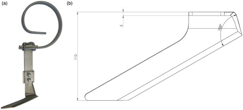
The new L-shaped share (L-share) designed for inter-row weeding was mounted on a modified spring tine ((a)). The L-share was developed by Agro Intelligence ApS in Denmark and consists of a vertical shank and a horizontal cutting blade (wing) perpendicular to the vertical shank. The wing has a nose angle of 105°, a thickness of 5 mm and a share width of 110 mm ((b)). The vertical shank ensures that the soil is mainly tilled where the wing operates, minimising lateral soil movement. The L-share was designed to operate in pairs, with an L-share placed either side of the inter-row space and the vertical shank positioned closely along each crop row. The share was operated close to the crop with the wing pointing away from the crop row. The tine consists of a flexible part and a stiff part. This design ensures that the tine can deflect from the vertical position if the horizontal blade impacts hard soil, stones or other solid obstacles.
Figure 3. The L-share: (a) image of the L-share mounted on a spring-modified tine and (b) drawing of the L-share.
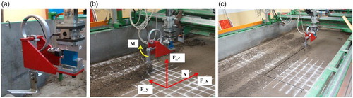
The soil movement and draught forces of the L-share were studied in a rectangular stationary soil bin at the Warsaw University of Life Sciences in Poland. The bin was 10 m long, 2 m wide and 1 m deep (), with two rails on top of each side along which a carriage was pulled/pushed. The carriage consisted of a frame with profiles on which the L-share was mounted, along with a levelling scraper and a compacted roller. The carriage moved at three constant speeds using an electrical motor, with its gearbox controlled by a computer (electrical motor WAR 16 1M4 TF, 22.0 kW; gearbox FUA 85A 16 1M4 TF; inverter V2500-0220 TFW1, Watt Drive, Austria). An optical sensor measured the operation speed, a force transducer (CS3D, ZEPWN, Marki, Poland) measured longitudinal, vertical and lateral forces (x, y, z direction), and a laser distance gauge (LDS 100-500P-S, Beta Sensorik) measured the distance between the tool frame and the soil level to ensure the desired cultivation depth of the share. The control and data acquisition system of the bin consisted of a computer that controlled five input/output (I/O) modules through a high-speed digital interface board (Hottinger Baldwin DMC plus). The data acquisition system for the force measurements ran in CATMAN 2.1 software, which ensured simultaneous acquisition of the experimental data at a sampling rate of 50 Hz.
Figure 4. The soil bin facility at the Warsaw University of Life Sciences, Poland: (a) a force transducer, (b) directions of draught forces axes: longitudinal Fx, N – negative values; lateral Fy, N – negative values; vertical Fz, N – positive values; the torque M, Nm around vertical Fz axes – positive values, and c) the soil bin with the axes of the soil movement.
The investigations were undertaken in a soil whose physical properties are shown in . Before each treatment with the carriage, the soil was compacted to a bulk density of 1500 kg m−3 and penetration index of 486 kPa verified by a 0.02 m cone, and had a mean soil water content of 10.0% (standard deviation 0.5%). A rolled surface was prepared in order to provide uniform test conditions for each treatment. Between each treatment, tines were used to loosen the soil to a depth of 0.22 m (±0.02). Nozzles were used to add water to ensure the correct water content, and the surface was levelled and compacted by the roller between each treatment. Further details about the soil bin for the experiment can be found in Lisowski et al. (Citation2016).
Table 1. Physical properties by weight of the experimental soil.
Treatments and experimental procedure
The experiment had two variables: cultivation depth (30 mm, 50 mm, and 70 mm) and operation speed (0.84, 1.67 and 2.31 m s−1). A clearance share angle of 0° was used. Each combination of cultivation depth and operation speed was replicated three times. The share forces were measured by an orthogonal force transducer in three directions (longitudinal Fx, lateral Fy and vertical Fz) and the torque M around vertical Fz axes.
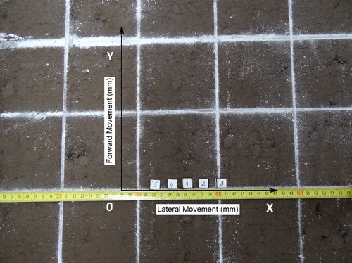
The soil movement around the L-share was measured using five 1000 mm3 plastic cubes (). The displacement of each cube from their initial positions was recorded for each treatment as the changes on the y and x axes. Cubes were placed at 20 mm intervals. The initial positions of the cubes were: cube № 5 x = 40 mm, y = 0; № 4 x = 60 mm, y = 0; № 1 x = 80 mm, y = 0; № 2 x = 100 mm, y = 0; № 3 x = 120 mm, y = 0 ().
Figure 5. Placement of cubes with initial coordinates before running the L-share: cubes № 5 x = 40 mm, y = 0; № 4 x = 60 mm, y = 0; № 1 x = 80 mm, y = 0; № 2 x = 100 mm, y = 0; № 3 x = 120 mm, y = 0.
In total, 27 treatments were conducted (3 cultivation depths × 3 operation speeds × 3 replicates = 27 treatments). Operation speed and cultivation depth were kept constant during each run with the carriage.
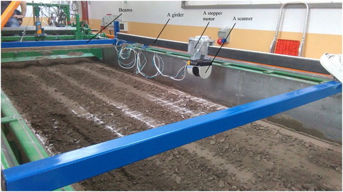
After each treatment with the L-share mounted on the carriage, soil disturbance (soil surface) and furrow profile (after removing the loosened soil) were measured by a 2D laser range scanner |LMS511-20100 PRO, 2012 () (SICK, Germany). Two lateral beams were used to carry the scanner. The beams were attached to 3-m-long girders upon which the scanner was mounted and moved in a longitudinal direction, 0.38 m above the surface (). The scanner moved at a speed of 0.0025 m s−1 and made four scans s−1 using a scan width of 0.5 m, with a standard error of 0.01 m. Scans were made after tillage and after removal of the loosened soil from the furrow profile (the uncultivated part of the lower soil layers after removing the loosened soil) to measure the furrow surface. The data obtained were processed and visualised as 3D images in MatCat (USA).
Figure 6. The soil bin with the beams and girder at the Department of Agricultural and Forest Machinery, Faculty of Production Engineering, Warsaw University of Life Sciences, Poland.
Statistical analyses
The effects of operation speed, cube number and cultivation depth on cube movement, draught forces and torque were analysed using a linear mixed model. The fixed effects were operation speed, cultivation depth, cube number and their mutual interactions for cube movements. For draught forces and torque the fixed effects were operation speed, cultivation depth and the interaction between the two factors. Model parameters were estimated using residual likelihood estimations. The statistical calculations were made with the mixed procedure of SAS (SAS release 9.2, SAS Institute Inc., Cary, N.C.) and means were calculated as least square means (LSM). Data were transformed whenever necessary to obtain homogeneity of variance. The specific transformations are shown in and .
Table 2. Significant main effects of cube number, operation speed and cultivation depth on x and y cube movements, with back-transformed least square means (LSMs) from log-transformation shown for each level of the factors
Table 3. Significant main effects of operation speed and cultivation depth on the draught forces Fx, Fy, and Fz including the inertia M. Least square means (LSMs) are shown for each level of the two factors. LSMs for Fx, Fy and M are back-transformed means from log-transformation, whereas LSM for Fz was from untransformed data
Results
The mean displacement of the cubes is shown in . The movement along the positive y-axis corresponds to the forward movement of the cubes from their initial position at y = 0. Likewise, the x-axis shows the lateral movements of the cubes. Both the x and y axes in show arithmetic mean values of the cube movements. The statistical analyses of the cube movements showed significant main effects of cube number, operation speed and cultivation depth, but non-significant interactions between the three factors for both x and y cube movements (). Cube number was clearly the most significant factor for both x and y movements. In particular, cube № 5 was moved markedly from its initial position, for example reaching x = 101 mm (SE = 18 mm) and y = 49 mm (SE = 9 mm) for the operation speed of 2.31 m s−1 and cultivation depth of 30 mm. Cube № 4 was the second most moved cube, while the differences between cubes № 1, 2 and 3 were minor. The smallest movements across the cubes were achieved with the operation speed of 0.84 m s−1 irrespective of cultivation depth, while the greatest movements were found with the operation speed of 2.31 m s−1 and cultivation depth of 30 mm. Increasing cultivation depth generally reduced x and y cube movements in contrast to increased operation speed (). It was calculated that for a cultivation depth of 50 mm, the operation speed should not exceed 3.89 m s−1 to avoid the crop plants being buried by the sideways movement of soil.
Figure 7. Mean displacements of individual cubes following L-share movements at operation speeds of 0.84, 1.67 and 2.31 m s−1 and cultivation depths of (a) 30 mm, (b) 50 mm and (c) 70 mm.
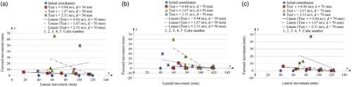
The L-share treatment at 70 mm cultivation depth with the operation speed of 2.61 m s−1 moved all the cubes to the right, while all the cubes were moved to the left with a cultivation depth of 30 mm and operation speed of 0.84 m s−1. At the operation speed of 0.84 m s−1 and cultivation depth of 50 mm, the cubes were not moved more than 10 mm from their initial positions in the y-direction. With a cultivation depth of 50 mm and operation speed of 0.84 m s−1 the soil movements were erratic: one third of the cubes were not moved in the y-direction from their initial positions, while one third were moved to the right and one third to the left. Treatments at the cultivation depth of 70 mm and operation speed of 0.84 m s−1 resulted in one third of the cubes not being moved from their initial y coordinates, while 53% of the cubes were moved to the right and 13% to the left. With the cultivation depth of 30 mm and operation speeds of 1.67 and 2.61 m s−1, cube № 5 was moved to the right.
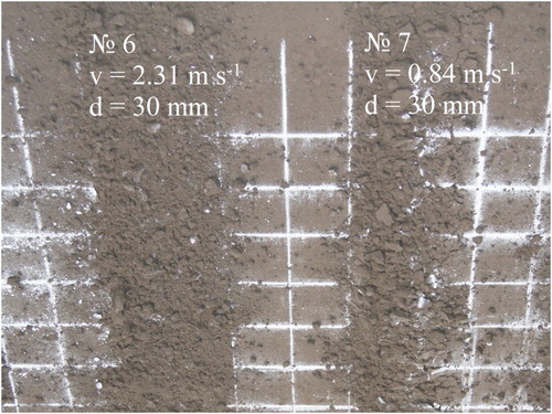
The image shown in visualises the soil disturbance caused by the L-share operating at 2.31 and 0.84 m s−1 at the cultivation depth of 30 mm. The vertical shank operated to the left of the disturbed soil surface. The operation speed of 2.31 m s−1 created a coarse soil surface with medium-sized aggregates, a dispersal width of 210 mm (S.E. ± 10 mm) and ridges greater than 10 mm. With the operation speed of 0.84 m s−1, the soil surface had larger aggregates with a dispersal width of 160 mm (S.E. ± 10 mm) and the ridges were also greater than 10 mm.
Figure 8. The soil surface following L-share treatments at operation speeds of 2.31 and 0.84 m s−1 respectively and cultivation depth of 30 mm
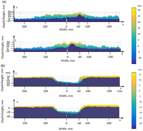
Examples of scans of the soil following operations at speeds of 2.31 and 0.84 m s−1 and at 30 mm cultivation depth are shown in as 2D figures of the soil profiles ((a,b) and of the furrow surfaces ((c,d)). The stiff shank of the L-share moved x = − 60 mm (right of the 0 position (x = − 60). The flexible part of the modified spring tine was subjected to bending and twisting, which was caused by draught forces generated by the soil. Draught forces from the soil caused the horizontal part of the L-share to move slightly upwards, with the point being moved by a maximum of 10 mm (S.E. ± 2 mm). This explains why the furrow surface was not exactly parallel to the soil surface, meaning that the deepest cultivation depth was achieved where the horizontal blade meets the vertical shank: the furrow surface shown to the right of x = 0 mm in (c,d). The highest ridge reached 32 mm at an operation speed of 0.84 m s−1 and 30 mm cultivation depth. When operating at 2.31 m s−1, a wider band of crumbled soil with a small ridge was created ((a)), compared to the operation speed at 0.84 m s−1 that created a narrower band but a higher ridge ((b)). The furrow surface was unaffected by the operation speed, whereas cultivation depth influenced the size of the trapezoidal form of the soil profile, which seems to be a typical shape following L-share treatment.
Figure 9. 2D images of the soil profile at a cultivation depth of 30 mm and operation speeds of (a) 2.31 m s−1 and (b) 0.84 m s−1, and of the furrow surface of the soil at a cultivation depth of 30 mm and operation speeds of (c) 2.31 m s−1 and (d) 0.84 m s−1 after L-share treatments.
Draught forces (Fx, Fy, Fz) and torque (M) were all significantly affected by both operation speed and cultivation depth, however they were not significantly affected by the interactions between the two factors (). Cultivation depth rather than speed explained more of the variance of the draught forces and torque on the L-share during operation. The forces Fx, Fy and torque M increased proportionally with increasing cultivation depth, while an inverse relationship was seen for Fz. The lowest operation speed at 0.84 m s−1 resulted in significantly smaller Fx, Fy and M values, but a greater Fz value when compared to the other two operation speeds. Increasing the operation speed from 1.67 to 2.31 m s−1 did not significantly change the draught forces and torque irrespective of the cultivation depths (). In general, Fx, Fy and M were most strongly affected by operation speeds > 0.84 m s−1 at cultivation depth 70 mm, while the opposite was true for Fz at 0.84 m s−1 and 30 mm cultivation depth. The draught force increased with increasing cultivation depth. When changing the cultivation depth from 30 to 50 mm and from 50 to 70 mm, the longitudinal force Fx increased by 63% and 71% respectively.
The impact on the L-share exerted by the draught force from the soil caused the modified spring tine to move backwards when operating at 50 mm cultivation depth and operation speed of 1.67 m s−1. In this case, the longitudinal force Fxmax = −243 N, the lateral force Fymax = 90.94 N, the vertical force Fzmax = −67.63 N and the torque Mmax = 105.05 Nm.
Discussion
The initial position of each cube was particularly important for both the direction and magnitude of soil movements. Cubes close to the vertical shank were moved at a greater magnitude in both directions from their initial positions, depending on the operation speed and cultivation depth. Operation speed not only affected soil movement, but also the degree of soil loosening, which is in accordance with Marakoglu and Carman (Citation2009). Both operation speed and cultivation depth affected the degree of soil loosening caused by the L-share. The greatest degree of soil loosening was found at a high operation speed and shallow cultivation depth.
The torque twisted the tine and vertical shank of the share. The degree of twisting depended on the operation speed and cultivation depth. The twisting of the shank also influenced the direction of soil movement. Godwin and Spoor (Citation1977) and McKyes (Citation1985) termed ‘critical depth’ to be when soil only moves in one direction, with lateral failure only occurring below this critical depth. For the L-share experiment, the critical depth was found to be 50 mm.
All tines have critical working depths, and desired soil movements will not occur when shares operate below this depth (Spoor and Godwin Citation1978; Marakoglu and Carman Citation2009). This critical depth depends on the configuration of tine and share, the share rake angle and the water content and bulk density of the soil.
The vertical shank of the L-share (the vertical part of the share) affects the soil movement and protects the plants from intense lateral soil movement. The soil does not accumulate around the plants, and ridges in the rows are not formed because the vertical shank acts like a protective shield. Desbiolles and Saunders (Citation2006) observed that increasing the thickness of the shank by a factor of 3 increased the soil throw index by 40% to 50%. The majority of the thrown soil was generated by the vertical shank.
The shank has a sharp chamfer (the sharpest part of the shank ()). With a share rake angle of 0 °, soil movement decreases with the L-share, even at high operation speeds and shallow cultivation depths. A major advantage of the L-share is that soil disturbance is reduced, even at high operation speeds. Thus, the risk of covering crop plants with too much soil will be reduced even when operating in narrow row spacing, and the L-share can be functional without any protective discs or shields. Protective discs or shields are normally required with sweeps for example, to avoid burying the crop with excessive soil, especially during early growth stages.
Using a sweep for weed control at early growth stages has been found to be less effective than the DF-share (Pullen and Cowell Citation1997). On the other hand, the sweep was found to be more effective in the later growth stages (Home Citation2003).
The chamfer of the L-share reduced lateral soil movement, which was also confirmed by Solhjou et al. (Citation2012). A DF-share has complex shapes on the shank and on the share (convex-concave), which may cause undesirable intensive soil movement and substantial mixing of the topsoil (Chen et al. Citation2013).
Soil movements with the L-share have been found to be less intensive than with the DF-share. At an operation speed of 0.84 m s−1, the soil movements with the L-share were 86% and 49% less in the x and y directions respectively, while the difference was 81% (x-direction) and 63% (y-direction) for 2.31 m s−1 (Znova, unpublished data).
The study by Pullen and Cowell (Citation1997) confirmed that increasing the operation speed improves the ability of the sweep and DF-share to control weeds. However, at operation speeds of between 1.4 and 3.1 m s−1, the improvement was only significant for the sweep.
The sweep angle, the angle between the vertical shank and the cutting blade, should be 95°. Soil forces cause the blade of the L-share to move slightly upwards, resulting in the outer part of the blade in particular to shift from the desired horizontal position, thus reducing its weeding effectiveness.
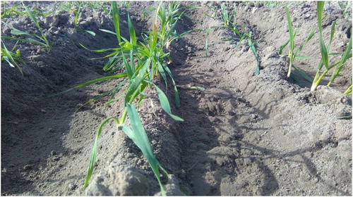
The L-share generated large soil aggregates with low operation speeds and at great cultivation depths. The roots of weeds may be embedded in large soil aggregates () and small weed plants may therefore continue to grow after inter-row cultivation, particularly after rainfall. This can reduce the over-all weed control effect and will require additional treatment for sufficient weed control (Melander et al. Citation2015). The removal of loose soil after an L-share treatment clearly revealed a curvilinear and distinct transition to the untreated and naturally compacted part of the soil profile. Such a profile can provide better growing conditions for the crop: the root system is protected and the water supply and uptake of nutrients are improved (Blum Citation2011). The required draught forces for the L-share were considerably lower than those measured for the DF-share in previous studies (Marakoglu and Carman Citation2009; Lisowski et al. Citation2016). The draught force of the L-share increased linearly with increasing cultivation depth, a result similar to the study by Marakoglu and Carman (Citation2009). Draught force is also affected by other factors such as operation speed and share configuration (Perumpral et al. Citation1983). An increased draught force also means additional fuel consumption (Natsis et al. Citation1999).
Figure 10. Image of the furrow surface following cultivation with the L-share at 50 mm soil depth and operation speed v = 0.84 m s−1 (field experiment 1 October 2015, Department of Agroecology, Faculty of Science and Technology, Research Center Flakkebjerg, Aarhus University).
Acknowledgements
Special thanks go to the staff at the Faculty of Production Engineering, Warsaw University of Life Sciences, for their support and commitment in performing the experiments.
Disclosure statement
No potential conflict of interest was reported by the authors.
Notes on contributors
Liubava Znova is an R&D engineer at Agro Intelligence ApS in Aarhus, Denmark. Qualification - research engineer of agricultural production technical support. Speciality - processes, machinery and equipment of the agro industrial enterprises at the engineering and technological department, Poltava State Agrarian Academy, 1/3 Skovorody str., Poltava, 36003 Ukraine. She has co-authored 2 scientific papers on the fields of farm machinery. Presently, she is studying the farm machinery and interaction between the working tools with soil.
Bo Melander is an Associate professor at the Department of Agroecology, Aarhus University, Forsøgsvej 1, DK-4200 Slagelse. He has authored and co-authored 41 scientific papers and book chapters in the field of weed biology and non-chemical weed control. Currently, he is studying the use of cultural, mechanical and thermal weed control methods for agricultural and horticultural crops.
Aleksander Lisowski is a Full Professor at the Department Agricultural and Forest Engineering, Faculty of Production Engineering, Warsaw University of Life Sciences - SGGW, Nowoursynowska 166, 02-787 Warsaw. He has authored or co-authored over 150 scientific papers and 27 monographs, textbooks or chapters in these publications on the fields of soil and plant technique and technology; machine design; conversion of biomass into solid fuels and gaseous. Presently, he is working on biomass compaction and development of anaerobic digestion technology. He has supervised eight doctoral theses; 12 research projects and 74 subjects of research and development or expertise as a manager. He is an expert on the evaluation of research proposals and investment projects and editor-in-chief of the scientific journal of Annals of Warsaw University of Life Sciences - SGGW Agriculture (Agricultural and Forest Engineering).
Jacek Klonowski is an Associate Professor at the Department Agricultural and Forest Engineering, Faculty of Production Engineering, Warsaw University of Life Sciences – SGGW, Nowoursynowska 166, 02-787 Warsaw. He has authored or co-authored over 60 scientific papers and 12 monographs, textbooks or chapters in these publications on the fields of soil and plant technique and technology, working resistance and power of agricultural machinery, indirect monitoring methods of plant material flow rate in the forage harvesters. Presently, he is working on the influence of soil humidity level and geometrical penetrometer cone dimensions on readings in soil compaction measurements.
Jarosław Chlebowski is an Associate Professor at the Department Agricultural and Forest Engineering, Faculty of Production Engineering, Warsaw University of Life Sciences - SGGW, Nowoursynowska 166, 02-787 Warsaw. He has authored or co-authored over 40 scientific papers on the fields of soil and plant technique and technology; energy crop harvesting; safe use of products; amaranth threshing; and mechanization of animal production. Presently, he is working on the mechanical cut weeding.
Gareth T. C. Edwards gained his Ph.D. from Aarhus University in 2015, focusing on field readiness for agricultural operations. He has co-authored over 5 scientific papers on soils’ workability for tillage operations and operational optimisation. Presently, he is working for Agro Intelligence, a precision agriculture OEM, and is Chief Scientist.
Søren Kirkegaard Nielsen is a research and development engineer employed at Agro Intelligence ApS, enrolling in an industrial Ph.D. at Aarhus University of Denmark, department of agroecology. He has a Master degree in Biosystems Engineering from Aarhus University and a bachelor degree from Aarhus School of Marine and Technical Engineering in Denmark. He has published different papers i.e. 'Sensor and control for consistent seed drill coulter depth', 'Seed drill instrumentation for spatial coulter depth positioning' in Comput. Electron. Agric. Comput. and 'Plough section control for optimised uniformity in primary tillage' in Advances in Animal Biosciences. He has also presented his studies at different conferences i.e. 'ISTRO' International Soil Tillage Research Organisation in China and 'ECPA' European Conference on precision agriculture in UK.
Ole Green has a background with an agricultural engineering and an agronomy degree, with a PhD from the Dept. of Engineering at Aarhus University. His research expertise covers: The interaction within tillage, soil compaction and soil fertility from a multidisciplinary perspective. Precision farming technologies, specifically within soil tillage optimization and crop establishment. And Farm management systems for tillage and crop growth optimization, route planning and operations optimization. In addition, Ole is a Honorary Professor in technology and intelligent solutions for sustainable soil management at the Department of Agro Ecology, Aarhus University.
Additional information
Funding
References
- Alexandrou A, Coffing G. 1998. An assessment of the performance of mechanical weeding control mechanisms used in north central ohio for maize and soybean crops. In: 2001 ASAE annual meeting. Vol. 1. American society of agricultural and biological engineers.
- Blum A. 2011. Plant breeding for water-limited environments. Tel Aviv, Israel: Springet.
- Chen Y, Munkholm LJ, Nyord T. 2013. A discrete element model for soil-sweep interaction in three different soils. Soil Tillage Res. 126:34–41. doi: 10.1016/j.still.2012.08.008
- Desbiolles JM, Saunders C. 2006. Soil throw characteristics of no-till furrow openers: a pilot study [doctoral dissertation]. Kiel (Germany).
- Godwin RJ, Spoor G. 1977. Soil failure with narrow tines. J Agric Eng Res. 22:213–228.
- Home M. 2003. An investigation into the design of cultivation systems for inter- and intra-row weed control [EngD thesis]. Silsoe: Cranfield University.
- Husted S, Bügel S. 2009. Økologi og Sundhed-fornuft eller følelse. ICROFS nyt. 1:4–5.
- Lisowski A, Klonowski J, Green O, Świetochowski A, Sypuła M, Struzyk A, Nowakowski T, Chlebowski J, Kamiński J, Kostyra K, et al. 2016. Duckfoot tools connected with flexible and stiff tines: three components of resistances and soil disturbance. Soil Tillage Res. 158:76–90. doi: 10.1016/j.still.2015.12.003
- Marakoglu T, Carman K. 2009. Effects of design parameters of a cultivator share on draft force and soil loosening in a soil bin. J Agron. 8:21–26. doi: 10.3923/ja.2009.21.26
- McKyes E. 1985. Soil cutting and tillage. Ste-Anne de Bellevue, Quebec: Elsevier. (Developments in Agricultural Engineering; vol. 7).
- Melander B, Lattanzi B, Pannacci E. 2015. Intelligent versus non-intelligent mechanical intra-row weed control in transplanted onion and cabbage. Crop Prot. 72:1–8. doi: 10.1016/j.cropro.2015.02.017
- Melander B, Rasmussen I, Bàrberi P. 2005. Integrating physical and cultural methods of weed control— examples from European research. Weed Sci. 53:369–381. doi: 10.1614/WS-04-136R
- Natsis A, Papadakis G, Pitsilis J. 1999. The influence of soil type, soil water and share sharpness of a mouldboard plough on energy consumption, rate of work and tillage quality. J Agric Eng Res. 72:171–176. doi: 10.1006/jaer.1998.0360
- Perumpral JV, Grisso RD, Desai CS, Perumpral JV, Grisso RD, Desai CS. 1983. A soil-tool model based on limit equilibrium analysis. Trans ASAE. 26:0991–0995. doi: 10.13031/2013.34062
- Pullen DWM, Cowell PA. 1997. An evaluation of the performance of mechanical weeding mechanisms for use in high speed inter-row weeding of arable crops. J Agric Eng Res. 67:27–34. doi: 10.1006/jaer.1997.0148
- Solhjou A, Fielke J, Desbiolles J. 2012. Lateral translocation of surface soil by various no-till narrow point openers. Agrociencia. 16:336–342.
- Spoor G, Godwin RJ. 1978. An experimental investigation into the deep loosening of soil by rigid tines. J Agric Eng Res. 23:243–258. doi: 10.1016/0021-8634(78)90099-9
- Van Der Weide RY, Bleeker PO, Achten VTJM, Lotz LAP, Fogelberg F, Melander B. 2008. Innovation in mechanical weed control in crop rows. Wejed Res. 48:215–224.
- Weiss A, Hirshberg D, Black MJ. 2011. Home 3D Body Scans from Noisy Image and Range Data † Perceiving Systems Dept., Max Planck Institute for Intelligent Systems, T. Work:1951–1958.