Abstract
Newer silicon-based consumer electronics became very popular due to its reduction in size, price, and power consumption. One of its applications today is building low-power devices for ubiquitous sensing. Although sensors are low-power devices, they need some energy source to function properly. One of the major challenges today is to develop systems where sensors do not require external power sources, and could be powered using available ambient energy. To address this power issue one could use energy harvesting concepts. In this paper, we present our probabilistic approach used for modeling the possible amount of Global System for Mobile Communication (GSM) energy that could be harvested, including a demonstration of what power levels could be harvested using GSM rectifying antenna (rectenna). In addition to harvesting approach, we propose an application of its usage in increasing the communication range between Radio Frequency Identification (RFID) reader and battery free passive RFID tags.
1. Introduction
Low-power electronic devices became very popular for the design of sensors and its networks. Its deployment enables a different range of applications including environmental control, home automation, activity monitoring, etc. Energy-efficient performance is a critical constraint in a sensor network deployment, as it would be difficult to change or recharge batteries in inaccessible deployment regions. Several proposals have addressed the energy efficiency, through the design of energy saving Medium Access Control (MAC) protocols, such as duty cycling protocols Citation[1] or low-power wake-up radio protocols Citation[2], and routing protocols, such as Citation[3,4].
According to Citation[5], the power consumption of a sensor node has been estimated by various authors, recent works quote values between 1 and 20 μW. Consumption strongly depends on the complexity of the sensed quantity and on the number of times per second it has to be transmitted. Practical implementation of a sensor node shows that 90 μW is enough to power a pulse oxymeter sensor, to process data and to transmit them at intervals of 15 s.
To address the problem of sensor powering, energy harvesting could be a viable approach. Energy harvesting generally relies on the amount of available ambient energy levels and converts it into appropriate energy form.
Recently, RF energy harvesting became popular topic Citation[6,7], and to be more specific GSM energy harvesting, since it is present everywhere Citation[8–10]. Authors in Citation[5] report possibility of RF energy harvesting through WLAN and GSM.
In Citation[11], authors present a wireless sensor system powered by AM broadcast energy harvesting. They harvested the energy from several local AM stations and obtained a power of 82 μW which was sufficient to drive a basic wireless sensor, but the main drawback of this approach is a 10 m long horizontal antenna – very strong limitation which is not present in GSM-based harvesting.
Although energy levels harvested from GSM are low, it should be noted here that as the technology advances, the sensors will be smaller, more efficient, require less power, and the ambient RF energy could be an important additional power source in the future. As the application given in this paper, we consider its usage in ultra high frequency (UHF) 860–960 MHz RFID tags as sensor-based technology, since its power consumption is low Citation[12], has best price-performance ratio of RFID technologies overall Citation[13] and its antenna size requirements.
RFID’s are recently being considered to realize “smart dust” application in the sense of RFID Sensor Networks (RSNs) which combines advantages of RFID’s with the advantages of Wireless Sensor Networks (WSNs) Citation[14]. Such observation leads to the form of future Internet, which will be the Internet of things (IoT) and not only the Internet of computational devices like PC’s or PDA’s Citation[15]. Moreover, through data acquisition and processing devices it would provide capability to interact with the environment (sensory swarm) Citation[16] or even sense human health Citation[17]. However, to build IoT or to enable ubiquitous sensing, which is working with great performance, one needs to provide the power required for tags computing. Power levels which tags require to function properly are today still high and that is the main reason for obtaining their low reading ranges. One way to improve it is done by assisting the power.
Power assisted tags are studied recently in the literature. GSM power assisted UHF tags in the means of interference were observed by authors in Citation[18]. The authors’ paper focus was the influence of GSM on UHF RFID. The conclusion provided in the paper gives the improved performance of UHF RFID when RFID signal strength is not high enough to turn tag IC up. In such scenarios, GSM signal constructively interferes with RFID, and tag IC could be power assisted and thus turned on.
In this paper, we consider GSM energy harvesting, due to available power levels that could be harvested practically everywhere, and appropriate antenna sizes which could be implemented in small UHF RFID tags. First, we provide the analysis on present ambient GSM power levels. As GSM signal consists of uplink and downlink channel, each of them should be observed. While downlink power level is always present, and more or less constant (small power variations during the day), uplink power depends on the number of mobile phones in the vicinity of GSM energy harvester. Due to uncertainty of the number of mobiles, we provide probabilistic approach used for modeling the possible amount of GSM energy that could be harvested. To demonstrate the possibility of GSM signal energy harvesting, we have soldered a Villard charge pump and gave details in the GSM energy harvesting experiment section.
As a use-case scenario, we provide analysis on usage of harvested energy in extending reading range of UHF RFID tags. Using this approach one can overcome a number of tag reading problems, as stated in Citation[19]. Moreover, we present the concept of new Improved Tag which can harvest additional energy level used in the tag IC operations with the goal of extending tag reading range. However, the challenge of adapting both tag antenna and power unit to harvest RFID and other signal sources is not discussed in details in this paper. So, the contribution of the paper is twofold: on the first, we present probabilistic model of the possible harvested energy from GSM, then, we present its application in extending reading range of UHF RFID tag.
The paper is structured as follows: in Section 2, we describe the passive UHF RFID tags and our Improved Tag scheme and in Section 3, we provide our probabilistic approach in modeling the possible amount of harvested energy. In addition, we discuss about the possible tag reading range increase with GSM power assisted passive tag. We also provide a GSM energy harvesting experiment for increasing the tag reading range in Section 4. Finally, we conclude our paper in Section 5.
2 Passive UHF RFID tags
Today, RFID is an integral part of our life, which increases productivity and convenience Citation[20]. Passive UHF Gen2 RFID Citation[21] technologies are recently being used for various identification and object tracking applications, tagging products in stores, building smart environments, etc.
In classic RFID system, RFID reader controlled by computer reads RFID tags through its antennas. Regarding tag battery presence or absence, RFID technology could be divided into full battery powered active RFID technology, battery assisted semi-passive RFID technology and battery free passive RFID technology. Another classification can be made regarding frequencies that reader uses to communicate with tags, where standards were developed for low frequency (LF – 125 or 134 kHz), high frequency (HF – 13.56 MHz), ultra high frequency (UHF – 860–960 MHz) or newly studied microwave frequencies Citation[12]. As the application given in this paper, we consider its usage in ultra high frequency (UHF) 860–960 MHz EPCglobal Citation[21] RFID tags since its power consumption is low Citation[12], has best price-performance ratio of RFID technologies overall Citation[13], and its antenna size requirements. GSM 900 MHz band is overlapping with UHF RFID and thus their antenna sizes are similar, providing compact tag-harvester design. In addition, other frequency bands for energy harvesting could be considered, but with appropriate antennas.
For UHF Gen2 passive tag to function properly, the antenna needs to deliver enough power to turn its Integrated Circuit (IC) on and its range depends on the efficiency of the tag antenna, rectifier, and IC power consumption. Detailed discussion on read range of passive UHF RFID tags can be found in Citation[22]. If one can assist tag powering, then reading range would be backward link limited due to reader sensitivity. Range of reading power assisted RFID tags can be up to 50 m Citation[23]. Providing extra power to assist RFID tag powering (using battery) makes technology semi-passive. However, this way of providing extra power based on energy harvesting makes technology not battery assisted, but energy harvesting assisted RFID and if enough power could be provided to tag IC, its performance could reach performance of battery assisted RFID technology. Tag IC typically consumes 10–30 μW of power, when they are being read Citation[12]. If the antenna was ideally matched and there were no losses in tag circuitry, all the power received would be available on tag’s IC. This is not the case in reality, although state-of-the-art CMOS rectifier designs can achieve very high efficiencies. More details on tag ICs’ power consumption and rectifier efficiencies are given in Section 3.4.
With obtained power lower than minimum, tag IC could not be turned on, and thus could not respond back to the reader.
To address the problem our Improved Tag scheme which is depicted in Figure could be used. The main idea is to use GSM energy to assist tag powering. In such case power unit can use additional energy and supply tag IC to turn it on. Moreover, Improved Tag could be optimized to receive signals from GSM bands, Digital Video Broadcasting (DVB) signals, different RFID readers signal, etc. When all signals are gathered, all the RF energy is rectified in the power unit and supplied to the tag IC.
Figure 1 Improved tag scheme.
Input for demodulation is set after the filter, which filters the signal only from RFID reader. The filter has its central frequency same as the one from the RFID reader interrogating tags. Filter is used to isolate only reader signal, and thus increase the probability of reader signal demodulation and decoding without errors.
When the reader signal is properly demodulated, and tag IC charged, tag will respond with the appropriate command.
For assisted tag powering, in this paper, we observe GSM-900 signal spectrum from spectrum analyser measured with quarter wave ground plane antenna (3 dBi gain). Example of GSM channel is depicted in Figure when the mobile phone is ringing one meter away from measuring antenna of spectrum analyser. Trivial example of integrating such channel shows that we obtain additional power of −10 dBm (100 μW) which can be used to assist tag powering. When the ringing mobile phone is moving away from the tags, as it is depicted in Figure , signal level is exponentially dropping. So, moving mobile phone to the tags in the moments of ringing can provide additional power. If RFID system is near GSM base station or there are more mobile phones in the neighborhood of RFID tags, more energy could be harvested and thus reading range increased.
Figure 2 (a) Signal strength of GSM channel when mobile phone signalization is active 1 m away from measuring antenna and (b) Decreasing signal strength from mobile phone in the moments of ringing.
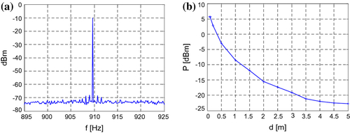
To elaborate what power level one can obtain from GSM uplink and downlink, we provide the analysis in the next section.
3 GSM energy harvesting – probabilistic approach
GSM allows for use of duplex operation – each band has a frequency range for the uplink and a separate range for the downlink. In the case of harvesting GSM energy, one should consider the contribution from both downlink and uplink GSM bands.
3.1 Downlink GSM energy
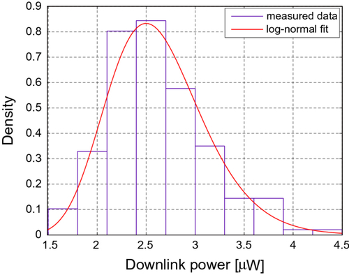
Downlink energy is always available and is dependent on number and distance from base stations. Total downlink GSM power was measured with spectrum analyzer at one location in our university building. It oscillated around −26 dBm (2.5 μW) as shown in the histogram in Figure . Measured data can be well fitted with log-normal distribution with parameters and
. We were measuring signals from GSM-900 band which uses 890–915 MHz for uplink and 935–960 MHz for downlink. We also conducted several more measurements at different locations and obtained similar data which can be well fitted with log-normal distribution.
Figure 3 GSM downlink power distribution with log-normal fit.
While downlink power level is always present, and more or less constant (we observed only small power variations during the day), uplink power depends on the number of mobile phones in the vicinity of GSM energy harvester. Due to uncertainty of the number of mobiles, we provide a probabilistic approach for modeling the possible amount of GSM energy that could be harvested.
3.2 Uplink GSM energy
Uplink GSM power is dependent on number of nearby mobile phones in an active call. Suppose we are considering only mobile phones in 10 m radius (more distant ones would have practically insignificant impact on measured power). Number of active mobile phones can be modeled with Poisson distribution. It is used to model the number of events occurring in a fixed interval of time and/or space with a known average rate and independently of the time since the last event. For example in Citation[24], calls are generated in the system simulator based on Poisson call arrivals.
Let us consider mean value , i.e. on average there are three mobile phones talking in the 10 m radius (area of 314 m2). This estimate is certainly too large for some rural areas, but considering typical places where RFID systems can be used, such as schools and universities, hospitals, supermarkets, public transportation and sports events, the mean number of three active mobiles is, in our opinion, a realistic estimate. For a given
, probability of any number of mobile phones talking is then given by
(1)
where n is a number of mobile phones.
Power of a single mobile phone is dependent on channel conditions and distance from a base station which is connected to. At the observed location, we measured around −15 dBm (32 μW) at 1 m from a mobile phone. In rough approximation, power of a mobile phone vs. distance could be modeled with a simple inverse-square law, i.e. mobile phone power (in μW) is . Then, the total uplink power
can be expressed as
(2)
where n is a number of mobile phones (N can be arbitrarily large), p(n) is the probabilities of scenarios with 1, 2, 3, and so on mobile phones, and is the total power of mobile phones in a specific scenario where
is a random number representing distance from a mobile phone (phones are assumed to be uniformly distributed from 0 to
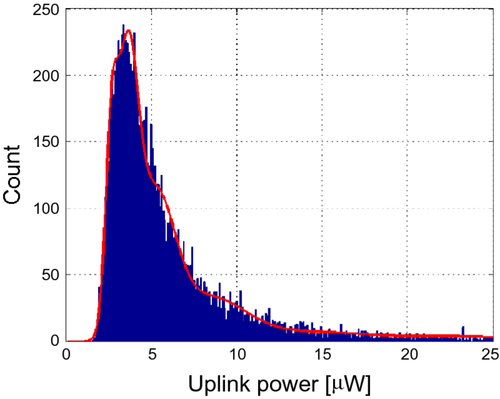
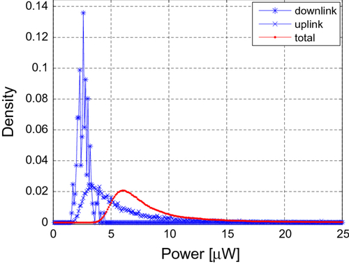
). This can be easily simulated, and Figure shows a histogram of total uplink power fitted with GMM (Gaussian Mixture Model) distribution. GMMs are widely used to model complex distributions and we achieved a good fit for our data. So by using the GMM model, analytical expression for total uplink power distribution was obtained. We used a 10 Gaussians mixture model:
(3)
Figure 4 GSM uplink power distribution.
with parameters ,
and
.
3.3 Total GSM energy
Since downlink and uplink power distributions can be considered independent, probability distribution of a total power can be obtained by their convolution and is shown in the Figure .
Figure 5 GSM uplink, downlink, and total power distributions.
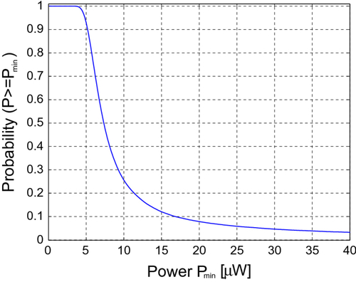
From the total GSM power distribution , probability of achieving at least
power can be easily calculated as
. For example, in 95% of cases total power would be at least 4.8 μW, in 50% of cases would be at least 7.34 μW and in 10% of cases it would be at least 16.8 μW (Figure ).
Figure 6 Probability of achieving at least power.
3.4 Improved Tag performance
The power received by tag can be expressed in simplified form by Friis equation with additional term representing the harvested power(4) where power levels
,
and
are given in Watts.
and
are reader and tag antenna gains given in dBi.
is the wavelength in meters and
is the distance between reader and tag given in meters. Given equation represents simplified model, complete link budgets in tag–reader communication, dependence on polarization match coefficient, impedance match, tag radar cross section and reflections in room can be found in Citation[25,26].
For the values of ,
,
and
(30 dBm), the calculation of received power is depicted in Figure . Black line represents the power received by a standard UHF Gen2 passive tag, other lines represent the power received with additional GSM harvested energy. According to Citation[12] modern tag ICs typically consume around 10–30 μW for reading, in Citation[27] UHF RFID transponder IC with 16.7-μW minimum RF input power was presented, NXP Semiconductor’s UCODE G2iL(+) series ICs require 15.8 μW Citation[28], Impinj’s Monza 5 series ICs require 16.6 μW Citation[29] and Alien Technology’s Higgs series ICs require 14.1 μW Citation[30]. If the antenna was ideally matched and there were no losses in tag circuitry, all the power received would be available on tag’s IC. This is not the case in reality, although state-of-the-art CMOS rectifier designs can achieve very high efficiencies – up to 70% Citation[31–34], or even more when designed for higher input voltages/powers. But it should be noted here that the efficiencies at the operational thresholds are much lower. In Citation[35], for a 950 MHz RF input and 10 kΩ output load, post-layout simulation results confirmed a power conversion efficiency (PCE) of 57% at 2.5 μW input power for the proposed gate-boosted switched 4T-cell. Authors in Citation[36] obtained 50% rectifier efficiency at 4 μW input power. The efficiency peaks at about 350 mV/4.25 μW input amplitude/power. For amplitudes of 200 mV, efficiency drops to 40%.
Figure 7 Improved range reading with additional harvested energy.
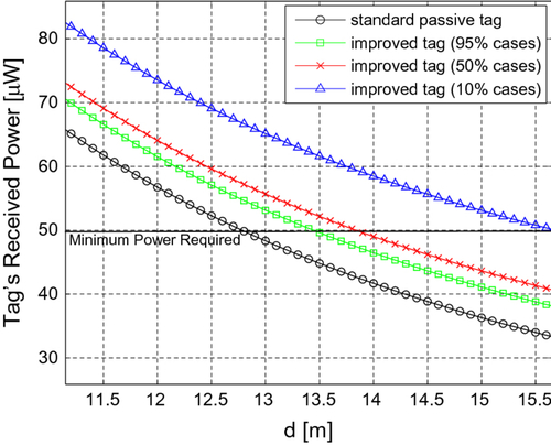
For simplicity and to be on the safe side, we plot a 50 μW line in Figure as the required received power, and obtain 12.8 m as the maximum reading range of a standard Gen2 passive tag. If we translate obtained GSM power (which would be lower in reality due to harvester efficiency) into the increase of a tag reading range, in 95% of cases we obtain range increase of 0.65 m, in 50% of cases range increase of 1.03 m and in the 10% of cases 2.85 m of increase.
Results given in the paper could be significantly improved if more mobiles are used, or in the areas which are near GSM base stations, DVB transmitters or the other transmitting sources. Moreover, reading range could be further improved if a ringing mobile phone is nearby, as can be seen from the power measurements in Figure .
4 GSM energy harvesting experiment for increasing tag reading range
To demonstrate the possibility of GSM energy harvesting and increased tag reading range for the experimentation, we soldered Villard voltage multiplier depicted in Figure . The multiplier consists of three stages, and it uses Avago’s HSMS-286C Schottky diodes (D1-D6) with high detection sensitivity and 2.5 pF capacitors (C1-C6). Schottky diodes are used because of their high speed and low forward voltage-drop.
Figure 8 Typical three stage cascaded Villard doubler circuit.
The harvester is very simple and certainly not of the state-of-the-art efficiency but our aim was not to build highly efficient rectifier, rather to demonstrate the concept of GSM energy harvesting in increasing tag reading range. Detailed description of a more efficient RF harvester for energizing low-power devices can be found in Citation[37].
Given soldered three stages Villard multiplier performance is tested by feeding it with 900 MHz Continuous Wave (CW) directly from the RF source and storing the harvested energy into AVX BestCap 10 mF super capacitor. To describe the performance of the harvester, we provide obtained voltages in Table for various input power levels with 10 kΩ load at 900 MHz. Results are similar to those we found in the literature Citation[8,10].
Table 1. Output voltage and power levels of GSM harvester with 10 kΩ load.
In order to demonstrate an increase in tag reading range, we used PowerID’s battery-assisted passive PowerG tags with Intermec IF5 reader (with 30 dBm output power and 6 dBi gain patch antenna). PowerG tag has a very thin 1.5 V battery, which we removed and connected the harvester output instead. This is shown in Figure with the measurement setup. Quarter wave ground plane GSM antenna (3 dBi gain) was connected to the harvester. Experiment was conducted in a hallway about 30 m long and 2 m wide. Energy was harvested from a ringing mobile phone about half meter away from the harvester antenna (about −3 dBm = 500 μW power measured with spectrum analyzer – Figure ).
Figure 9 GSM energy powered PowerG tag.
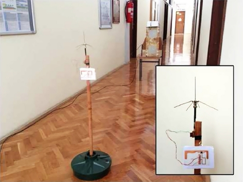
Without the harvester obtained reading range was about 2 m (passive tag), but with the harvester connected obtained range was extended to 20 m. Because of the high sensitivity of the PowerG tag, the RFID reader’s receiver sensitivity should also be high to be able to receive the signal, so if a more sensitive reader was used this range could be even higher, e.g. high sensitivity CSL CS462 reader recommended by the manufacturer.
5 Conclusions
In this paper, we present our probabilistic approach used for modeling the possible amount of GSM energy that could be harvested. As GSM signal consists of uplink and downlink channel, each of them was observed. While downlink power level is always present and more or less constant, uplink power depends on the number of mobile phones in the vicinity of GSM energy harvester. Due to uncertainty of the number of mobile phones, we have provided a probabilistic approach used for modeling the possible amount of GSM energy that could be harvested. To demonstrate the possibility of GSM energy harvesting and increased tag reading range, we have also conducted an experiment showing significant increase in reading range with harvested energy assisted tag powering. The challenge of adapting actual tag circuitry and antennas to harvest energy as it was proposed in this paper we leave for the future research.
Such extension in RFID reading range would allow a wider spectrum of usage, more convenient reading of tags in larger areas like large storage spaces, supermarkets, libraries, more convenient product tracking and inventory systems. This would also lead to a greener communication infrastructure due to less number of deployed readers.
Although energy levels harvested from GSM are low and are not sufficient for constant tag powering, as the technology advances, the sensors will be smaller, more efficient, require less power, and the ambient RF energy could become an important source of energy supply.
References
- Polastre J, Hill J, Culler D. Versatile low power media access for wireless sensor networks, SenSys’04. In: Proceedings of the Second International Conference on Embedded Networked Sensor Systems; 2004; Baltimore, USA. p. 95–107..
- Gu, L, and Stankovic, JA, 2004. Radio-triggered wake-up capability for sensor networks, Proc. – IEEE Real-time Embedded Technol. Appl. Symp. 10 (2004), pp. 27–36.
- Ruzzelli, AG, O’Hare, GMP, and Jurdak, R, 2008. Merlin: cross-layer integration of MAC and routing for low duty-cycle sensor networks, Ad Hoc Networks. 6 (2008), pp. 1238–1257.
- Papadimitriou, I, and Georgiadis, L, 2006. Energy-aware routing to maximize lifetime in wireless sensor networks with mobile sink, J. Commun. Software Syst. (JCOMSS). 2 (2006), pp. 141–151.
- Vullers, RJM, van Schaijk, R, Doms, I, van Hoof, C, and Mertens, R, 2009. Micropower energy harvesting, Solid-State Electron. 53 (2009), pp. 684–693.
- Nishimoto H, Kawahara Y, Asami T. Prototype implementation of ambient RF energy harvesting wireless sensor networks. In: Proc. IEEE Seasors. 2010; Kona, USA. p, 1282–1287..
- Sample A, Smith JR. Experimental results with two wireless power transfer systems. In: Proc. IEEE Radio Wireless Symp. 2009. 2009: San Diego, USA. p. 16–18..
- Arrawatia M, Baghini MS, Kumar G. RF energy harvesting system from cell towers in 900 MHz band. In: 2011 National Conference on Communications, NCC; 2011. p. 1–5..
- Albasha L, Heydari Nasab S, Asefi M, Qaddoumi N. Investigation of RF signal energy harvesting. Active Passive Electron. Compon. 2010:1–6..
- Yan H, Montero JM, Akhnoukh A, de Vreede L, Burghartz J. An integration scheme for RF power harvesting. In: Proc. STW Annual Workshop on Semiconductor Advances for Future Electronics and Sensors; 2005. p. 64–66..
- Xie, K, Liu, Y-M, Zhang, H-L, and Fu, L-Z, 2011. Harvest the ambient AM broadcast radio energy for wireless sensors, J. Electromagn. Waves Appl. 25 (2011), pp. 2054–2065.
- Dobkin, D, 2008. The RF in RFID. Burlington: Elsevier; 2008.
- Michael K, McCathie L. The pros and cons of RFID in supply chain management. In: Proceedings of the International Conference on Mobile, Business (ICMB05); 2005. p. 623–629..
- Buettner M, Greenstein B, Wetherall D, Smith JR. Revisiting smart dust with RFID sensor networks. Proceedings of the 7th ACM Workshop on Hot Topics in Networks; 2008 Oct; Calgary, Canada..
- Roy, S, Jandhyala, V, Smith, JR, Wetherall, DJ, Otis, BP, Chakraborty, R, Buettner, M, Yeager, DJ, Ko, Y, and Sample, AP, 2010. RFID: From supply chains to sensor nets, Proc. IEEE. 98 (2010), pp. 1583–1592.
- Rabaey JM. The swarm at the edge of the cloud a new perspective on wireless. In: 2011 Symposium on VLSI Circuits Digest (VLSIC); 2011. p. 6–8..
- Marrocco, G, 2010. Pervasive electromagnetics: Sensing paradigms by passive RFID technology, IEEE Wireless Commun. 17 (2010), pp. 10–17.
- Souryal MR, Novotny DR, Kuester DG, Guerrieri JR, Remley KA. Impact of RF interference between a passive RFID system and a frequency hopping communications system in the 900 MHz ISM band. In: IEEE International Symposium on Electromagnetic Compatibility; 2010. p. 495–500..
- Dimitriou AG, Bletsas A, Polycarpou AC, Sahalos JN. Theoretical findings and measurements on planning a UHF RFID system inside a room. Radioengineering. 2011;20:387–397..
- Landt, J, 2005. The history of RFID, IEEE Potentials. 24 (2005), pp. 8–11.
- EPCglobalInc. Class 1 generation 2 UHF air interface protocol standard “gen 2”, v1.2.0. Tech. Rep., October 2008..
- Lazaro, A, Girbau, D, and Villarino, R, 2009. Effects of interferences in UHF RFID systems, Prog. Electromagn. Res. 98 (2009), pp. 425–443.
- Solic P, Radic J, Rozic N. Software defined radio based implementation of RFID tag in next generation mobiles. IEEE Trans. Consumer Electron. 2012;58:1051–1055..
- ETSI TR 145 903 V11.0.0. Digital cellular telecommunications system (phase 2+). Technical Report; October 2012. Available from: http://www.etsi.org/deliver/etsi_tr/145900_145999/145903/11.00.00_60/tr_145903v110000p.pdf.
- Nikitin PV, Rao K. Performance limitations of passive UHF RFID systems. In: IEEE Antennas and Propagation Society International Symposium; 2006. p. 1011–1014..
- Nikitin, PV, and Rao, K, 2006. Theory and measurement of backscattering from RFID tags, IEEE Antennas Propagat. Mag. 48 (2006), pp. 212–218.
- Karthaus, U, 2003. Fully integrated passive UHF RFID transponder IC with 16.7 μW minimum RF input power, IEEE J. Solid-State Circuits 38 (2003), pp. 1602–1608.
- NXP Semiconductors. UCODE G2iL(+) series tag ICs. Available from: http://www.nxp.com/products/identification_and_security/smar-t_label_and_tag_ics/ucode/..
- Impinj. Monza 5 series tag ICs. Available from: http://www.impinj.com/support/downloadable_documents.aspx..
- Alien Technology. Higgs 4 series tag ICs. Available from: http://www.ali-entechnology.com/tags/rfid_ic.php..
- Sasaki A.Differential-drive CMOS rectifier for UHF RFIDs with 66% PCE at 12 dBm Input. In: IEEE Asian Solid-State Circuits Conference; 2008. p. 105–108..
- Rabaey JM. Powering and communicating with mm-size implants. In: Design, Automation & Test in Europe Conference & Exhibition; 2011. p. 1–6..
- Wong, S-Y, and Chen, C, 2011. Power efficient multi-stage CMOS rectifier design for UHF RFID tags, Integration, VLSI J. 44 (2011), pp. 242–255.
- Monti, G, Congedo, F, de Donno, D, and Tarricone, L, 2012. Monopole-based rectenna for microwave energy harvesting of UHF RFID systems, Prog. Electromagn. Res. C 31 (2012), pp. 109–121.
- Kamalinejad P, Mirabbasi S, Leung VCM. An efficient CMOS rectifier with low-voltage operation for RFID tags. In: Proceedings of the 2011 International Green Computing Conference and Workshops; 2011. p. 1–6..
- Bakhtiar AS. An efficient CMOS RF power extraction circuit for long-range passive RFID tags [Master of Science Thesis]. University of British Columbia; 2011..
- Din, NM, Chakrabarty, CK, Bin Ismail, A, Devi, KKA, and Chen, W-Y, 2012. Design of RF energy harvesting system for energizing low power devices, Prog. Electromagn. Res. 132 (2012), pp. 49–69.