Abstract
The polarization-dependent properties of electromagnetic plane wave scattering from active cylindrical coated nano-particle (C-CNP) antennas are investigated in the visible frequency band. It is demonstrated with three independent orthogonal polarizations that the dipole mode is excited resonantly in each case, even though the resonant size of the particles, as seen by these normally incident plane waves, is different. Moreover, the scattering behaviors for various angles of incidence are studied. It is shown that the polarization state along the main axis of the cylinder dominates the scattering properties of these resonant, active C-CNP’s; and because of the natural symmetry, they mainly depend on the elevation angle α and not the azimuth angle β.
1. Introduction
Nano antennae are the key elements needed to transform electromagnetic waves to electrical signals or to amplify an electromagnetic signal in some volume. They are promising candidates as absorbers for photo-detector applications or as radiators in the areas of biology, medicine,Citation[1–3] efficient solar cells,Citation[4] high-resolution microscopy,Citation[5] and optical communications.Citation[6] As an enabling technology, they are particularly useful to achieve nano-sensors that could provide non-invasive measurements of the electromagnetic properties of molecules or composite particles. Because metals at visible wavelengths are epsilon negative materials, they can be coupled with dielectrics to enable plasmonic effects. In particular, this property has led to nano-sized plasmonic particles that can act as highly sub-wavelength lasing elements and nano-amplifiers.Citation[7]
The spherical shell plasmonic nano-particles, which consist of a metallic shell surrounding a dielectric core, are called spherical coated nano-particles (CNPs). It has been shown that they lead to novel optical properties, including resonant scattering, absorption, and transparency, and exhibit a geometric tunability. Highly sub-wavelength silver CNPs can be tunable over the visible part of the spectrum.Citation[8] The tunability of these CNP resonances is a desirable characteristic for realizing an ambient light display.Citation[9] If the core is filled with a lossless or lossy dielectric, the particle is called a passive CNP; the model of which has been discussed completely in Citation[7,9–11]. When a passive CNP is excited by a plane wave, its performance can be naturally characterized by the maximum absorption cross-section (ACS), scattering cross-section (RCS), and extinction cross-section, all of which depend on the radius of the core and the thickness of the metal film of the passive CNP. The optimum ratio of the SiO2 core radius to the silver shell radius for the maximum RCS of a SiO2–Ag passive CNP was determined to be 0.8.Citation[7] The resulting power distribution resembles that of a symmetrical dipole excited by the same electromagnetic wave. In addition to studies of plane waves exciting CNPs, the electric Hertzian dipole is another excitation choice that has been studied extensively.Citation[11] It has been shown that specific CNPs can be designed to be resonant, leading to much larger values of the normalized radiation resistance, thereby overcoming the intrinsic losses present in the plasmonic materials.
Another aspect and disadvantage of using metals at visible wavelengths are their large losses. These losses constrain the potential field enhancements associated with passive CNPs. As a consequence, gain material has been introduced into CNPs to overcome these losses and even exhibit gain.Citation[8,11–20] This concept has been validated experimentally.Citation[13] In Citation[21], for instance, Er3+-doped fiber amplifiers have spectral gain and associated refractive index spectra that can be calculated from the Kramers–Kronig relations. These results show the additional gain increase to be large and the gain-induced refractive index dispersion due to the real part of the atomic susceptibility in the amplifier to be negligible.Citation[11,22–24] In Citation[7,9–11], for instance, gain material was introduced into the core medium of the CNP to achieve negative values of the optical gain constant κ, the imaginary part of the refractive index: (n-jκ). Er3+-doped cores were considered originally.Citation[7] From the theoretical derivations and many simulations, such active CNPs show super-resonant lasing states, in which the negative absorption efficiency is 103 greater than their passive counter parts. The total efficiency of these super-resonant CNPs is more than 104, which leads to possible realizations of sub-wavelength lasers whose sizes are on the order of λ/20.
In addition to the active spherical CNPs, active one-end-open cylindrical CNPs,Citation[20] completely closed cylindrical CNPs,Citation[25] and infinitely long active CNPs of cylindrical shape Citation[26,27] have been characterized analytically and numerically. While many of the properties of the spherically symmetric optical nano-antennas have been studied analytically, most nano-particles have non-spherical shapes. This complication arises simply because of the available fabrication methods. On the other hand, the non-spherical structures, such as dielectric core-metallic shell prolate spheroid nano-particles Citation[28] or coaxial metal-dielectric structures,Citation[29] have their own characteristic advantages.
In a real-world situation, the orientations of a set of nano-particles may be rather disordered. Consequently, if the nano-particles are non-spherical, the excitation light will arrive from different directions and with various polarizations. One finds that the scattering properties of these classes of elongated nano-particles are very polarization dependent. We have investigated the scattering properties of several types of active cylindrical C-CNPs with the incident plane waves polarized along the axis of the cylinders, but having a variety of angles of incidence.Citation[20,25] We extend those studies in this paper to understand the polarization-dependent scattering properties of these C-CNPs. Aside from the theoretical knowledge of how changes from spherical to cylindrical shapes impact the polarization performance characteristics of active CNPs, these investigations have enhanced the potential use of C-CNPs for polarization-sensitive nano-sensors, for example, to distinguish molecular orientations in bio-assays. The materials and geometries used in our CST Microwave Studio (MWS) numerical simulations of these active C-CNPs are discussed in Section 2. The performance characteristics of the active C-CNPs excited by the three basic orthogonal polarization states of the incident plane wave are presented in Section 3. The general plane wave results are reported in Section 4. A summary is given in Section 5.
2 Dispersive model and study method
The CST MWS computational electromagnetic simulation tool set solves Maxwell’s equations in the time-domain based on the finite integration in time technique (a slight generalization of the finite-difference time-domain method), and in the frequency domain with the finite element method (FEM).Citation[30,31] With any real or artificial material, losses and, hence, dispersion effects must be taken into account. As reported previously,Citation[20,25] we have successfully incorporated gain-impregnated frequency dependent dielectric media into the FEM solver in CST MWS. As validation of the more general structures, it will be shown that the CST results obtained in this manner reproduce the analytically obtained ones for the canonical passive and active spherical CNPs.
2.1 Dispersive models
In linear isotropic homogeneous media, the electric and magnetic fields and their corresponding flux densities in the frequency domain satisfy the constitutive relations:(1)
(2) Losses lead to complex permittivity or permeability values. For example, the permittivity in a lossy dielectric takes the form:
(3) For simple conducting materials, the imaginary part is given explicitly as
(4) More complete material models are needed for general lossy and dispersive materials.
2.1.1 Drude model of the metal
At optical wavelengths between 200 and 1800 nm, the metal plasmonic shells are modeled with an empirically based Drude model,Citation[7,11,20,26] which recovers known experimental values.Citation[32] It takes into account the size dependent and interband effects on the permittivity values:(5)
In (5), the first part is the size-dependent Drude response, and the second part is the interband transition response. The term R is the thickness of the metal. The Drude permittivity is given by the expression:(6) where ωp and Γ, respectively, the plasma and the collision frequencies. The size dependence is treated as an effect which arises when the size of the material approaches and becomes smaller than the bulk mean free path length of the conduction electrons in it. It is treated as an alteration in the mean free path which is then incorporated into the Drude model through the size-dependent damping frequency, that is, the damping frequency is assumed to take the form:
(7)
where A is a constant term assumed to be approximately unity, that is, A ∼ 1. The term VF is the Fermi velocity. The Drude parameters and the Fermi velocity values used in our simulations for silver and gold are given in Table 1 in Citation[7].
2.1.2 Lorentz model for the gain material
The core of the CNP is filled with silicon dioxide, SiO2. This is a very low loss dielectric which has the relative permittivity: ϵr = 2.05, and, hence, the refractive index, . If the dielectric was lossy or amplifying, for example, it is doped by ions or gain material, the relative permittivity would be complex. The relative permittivity and the real and imaginary parts of the refractive index, n and, are related by the expression
(8)
Here, κ is varied over a range of values that represent the expected loss or gain in the core of the nano-shell, where κ > 0 (κ < 0) for a lossy (gain) medium. As in Citation[7,11,20,25,26], the active material in the core is specified by the value of κ. In this manner, it can represent the gain from dyes, rare-earth ions, or quantum dots, which have all been considered for these and related plasmonic structures.
If the material is resonant, as it would be in the presence of gain, its dispersive properties can be described by a Lorentz model Citation[33], that is, its relative permittivity can be written as(9) Here, ϵ∞ is the high frequency permittivity value, that is, the value when the frequency goes to infinity; and ϵS is the static permittivity value, that is, the value when the frequency is zero. To the gain-impregnated SiO2, we can set
and, for example, κ = −0.25 at the resonance frequency of the structure, f0 = 600 THz. Then, at f = f0, ω = ω0 = 2πf0, (9) yields:
(10) Combining Equations (3), (8) and (10), one obtains
1.9875 and
, so that
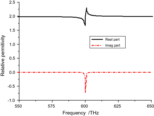
(11) Here, Γ is the collision frequency (or damping factor), which is related here to the resonant frequency of the model for simplicity. It is set in the range (10−3–10−1)ω0, to represent low to high loss materials. In the following cases, we choose Γ = 10−3ω0. The resulting real and imaginary components of the relative permittivity are shown in Figure . Note that because the medium is active, the signs and slopes of these components are opposite of what they would be if it were passive.
Figure 1 Relative permittivity of gain-impregnated SiO2 with Γ = 10−3 ω0 and ω0 = (2π) 600 × 1012.
2.2 Plane wave excitation performance terms
Generally, the RCS and ACS are the main figures of merit used to describe the performance of a nano antenna when it is excited by an electromagnetic plane wave. The RCS is defined as the total integrated scattered field power normalized by the irradiance of the incident field. The ACS is defined by the net flux through a surface surrounding the structure normalized by the incident field irradiance. Both the absorption and RCSs can be expressed via Poynting’s theorem through the power scattered and absorbed by the structure.Citation[20,25]
2.3 Cylindrical coated nano-particle model
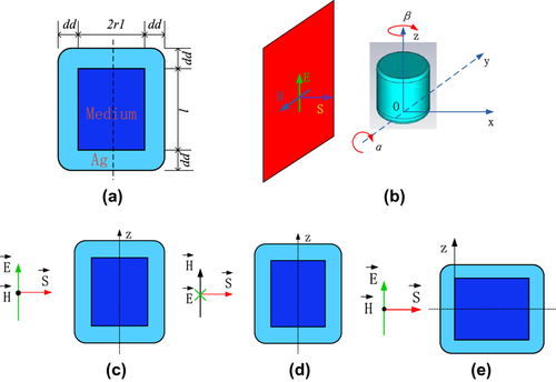
The cylindrical coated nano-particle (C-CNP) model is shown in Figure . Its symmetry axis is parallel to the Z axis. The shell is silver; as shown in Figure , it has a dd nm thickness. The cylindrical core is filled with the dielectric medium; it has a radius r1. The whole height of the C-CNP is l. The incident plane wave is assumed to be propagating along the X axis. To achieve an arbitrary polarization, the C-CNP is rotated through the angle α with respect to the Y axis and β with respect to the Z axis. These angles are shown in Figure .
2.3.1 Ez polarization wave
Three special cases are studied in addition to the general one. The first is shown in Figure ; it has α = β = 0° and the C-CNP is excited with a plane wave whose electric field is Z-oriented. This is called the Ez polarization wave and is explicitly given as:(12) where E0 is the magnitude of the incident field and k = ω/c, c being the speed of light, is the incident wave number.
Figure 2 Plane wave excited C-CNP model. The incident plane wave source has the wave vector (kx = 1, ky = 0, kz = 0). (a) CNP model and its parameters; (b) plane wave incident on the cylinder from different directions α and β; (c) Ez polarization, electric field vector along the (x = 0, y = 0, z = 1) direction and α = β = 0°; (d) Ey polarization, electric field vector along the (x = 0, y = 1, z = 0) direction and α = β = 0°; (e) Et polarization, electric field vector along the (x = 0, y = 0, z = 1) direction and α = 90°, β = 0°.
2.3.2 Ey polarization wave
The second, which is shown in Figure , has the same particle orientation, α = β = 0°, but the incident wave is Ey polarized, that is,(13) Thus, it is called the Ey polarization wave.
2.3.3 Et polarization wave
The third one is shown in Figure . The C-CNP is rotated by α = 90° and β = 0°; the incident wave is given by (11), that is, it has its electric field again along the Z axis. This will be termed the Et polarization wave.
An arbitrarily polarized plane wave incident along the α and β directions can be constructed as a weighted sum of these three cases.
3 Scattering behaviors of the three elemental polarization cases
3.1 Ez polarization
This case was studied originally in Citation[34]. The optimized parameter values for the passive C-CNP are r1 = 14.8 nm, l = 31.5 nm, and dd = 6 nm.The optimal parameter values for the active C-CNP are r1 = 15.5 nm, l = 31.5 nm, and dd = 6 nm. The maximum RCS is −106.84 dBsm, more than 35 dBsm above the passive case value. The nano-particle radiates in a fundamental electric dipole mode at the resonant frequency, 599.95 THz.
3.2 Ey polarization
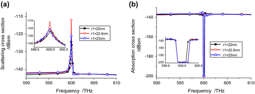
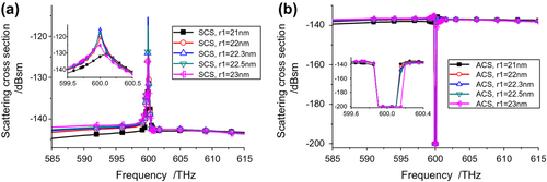
With the fixed height l = 31.5 nm, the model was run with the core radius being swept from 22 to 23 nm. The simulated scattering and ACSs are shown in Figure . From Figure , the optimum radius value for the C-CNP is found to be r1 = 22.6 nm. The optimized structure produces a peak SCS value: −111.93 dBsm at 600 THz. Note that this is about a 30 dBsm increase over the background values and is about −5 dBsm smaller than the Ez polarization value. For all simulated values of r1, the SCS peaks are very close to the desired 600 THz resonance frequency. Similar behaviors of the ACS curves are shown in Figure . The ACS minimum also occurs at 600 THz. The minimum is more than 50 dB below the background value. Both the SCS and ACS values clearly show a significant amplification of the scattered signal, that is, the active C-CNP acts as a nano-amplifier. The optimal C-CNP configuration for the Ey polarized incident wave is thus l = 31.5 nm, r1 = 22.6 nm, and dd = 6 nm.
Figure 3 Ey polarization results for C-CNP with l = 31.5 nm, dd = 6 nm, and its core radius swept from 22 to 23 nm. (a) Scattering, and (b) ACSs.
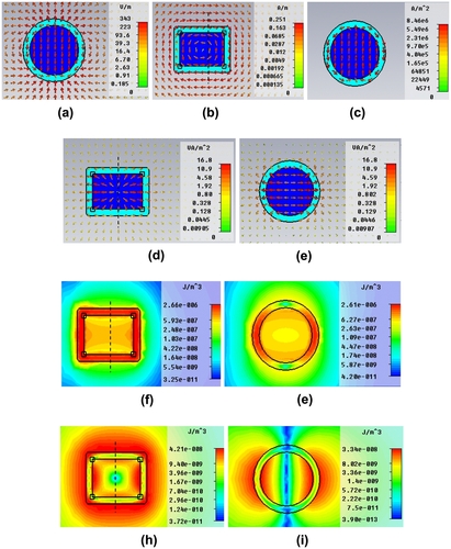
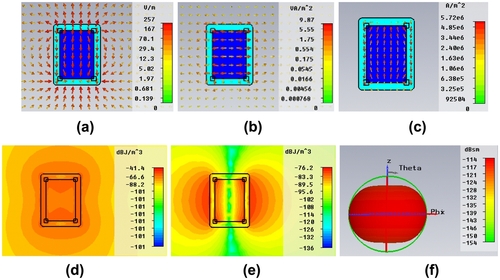
The predicted electric field, power flow, current densities, electric field energy density, and magnetic field energy density distributions for the optimized active C-CNP at the resonance frequency 600 THz are illustrated in Figure . The enhancement of the electric field in the core is clear in the zx-cut plane in Figure . The magnetic field distribution in the xy-cut plane in Figure also shows this enhancement. The field vectors in Figure clearly illustrates that the electric dipole mode is dominant at the resonance frequency. The corresponding enhancement of the current density in the core is shown in Figure . It is clear that there are very large currents formed in the core at the resonant frequency when the active medium is present. The power flow (Poynting vector field) is shown to be strongly outward, away from the core, in Figure . The corresponding magnetic and electric field energy distributions are shown, respectively, in Figure . The dipole pattern of the field at the resonance frequency is clearly seen in Figure .
Figure 4 Field distributions for the Ey polarization case in the xoy-cut and zox-cut planes at f = 600 THz. (a) Electric field in the zox-cut plane; (b) magnetic field in the xoy-cut plane; (c) current density in the zox-cut plane; power flow in the (d) xoy-cut and (e) zox-cut planes; electric field energy density in the (f) xoy-cut and (g) zox-cut planes; and magnetic field energy density in the (h) xoy-cut and (i) zox-cut planes.
3.3 Et polarization
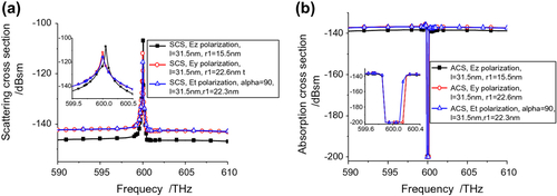
The setup for this case is shown in Figure . Again with the height fixed l = 31.5 nm, the model was run with the core radius being swept from 21 to 23 nm. The predicted scattering and ACSs are shown in Figure . From Figure , the optimum parameter value for the cylindrical particle antenna is found to be r1 = 22.3 nm. This structure produces a maximum SCS: −115.37 dBsm at 600 THz. Note that this is only about a 26 dBsm increase over the background values, about 4 dBsm smaller value than the Ey polarization case and 9 dBsm smaller than the Ez polarization case. For all simulated values of r1, the SCS peaks are close to 600 THz as shown in Figure . Similar behaviors of the ACS curves are shown in Figure . The ACS minimum also occurs at 600 THz. Again, the minimum is more than 50 dB below the background value. Both the SCS and ACS values clearly show a significant amplification of the scattered and absorbed responses. From these results, one finds that the optimized parameter values for the Et excited, active C-CNP are l = 31.5 nm, r1 = 22.3 nm, and dd = 6 nm.
Figure 5 Et polarization results for C-CNP with l = 31.5 nm, dd = 6 nm, and its core radius swept from 22 to23 nm. (a) RCS, and (b) ACS.
The predicted distributions of the electric field, current density, power flow, and electric and magnetic field energy densities for the Et polarization excited, optimized (with l = 31.5 nm, dd = 6 nm and r1 = 22.3 nm) active C-CNP at 600 THz are illustrated in Figure . Again, the enhancement of the electric and magnetic fields and the current density in the core is readily seen. The power density is clearly flowing outward away from the gain-impregnated core. The field behavior is dominated by the electric dipole mode.
Figure 6 Predicted distributions for the Et polarization case of the (a) electric field, (b) power flow, (c) current density, (d) electric and (e) magnetic field energy densities and (f) far field, 3D gain pattern for the optimized, active C-CNP with α = 90°, β = 0° at f = 600THz.
3.4 Comparisons
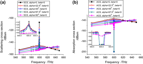
The results for the Ez, Ey, and Et polarization cases are readily compared. In each case, the optimized active C-CNP configuration has l = 31.5 nm and dd = 6.0 nm. For the Ez, Ey, and Et cases, the optimized core radius is, respectively, r1 = 15.5, 22.6, and 22.3 nm. The SCS and ACS results are directly compared in Figure , respectively. The background level for the Ez case is found to be lower than those of the Ey and Et cases. In fact the background mainly depends on the passive structure. On the other hand, as noted above, the SCS peak for the Ez excitation is significantly larger than for the Ey or Et excitations, while the Ey peak is larger than the Et one. These differences are exacerbated if the optimized Et configuration is selected since it would not be optimal for either the Ey or Et polarizations. Consequently, the Ez polarization will dominate the behavior for arbitrary angles of incidence and polarization states of the exciting plane wave. It is this polarization that excites the largest portion of the gain material coherently and, hence, leads to the large amplification.
Figure 7 Comparison of the (a) scattering and (b) ACSs for the three basic polarization cases.
4 Plane wave excitation of an arbitrarily oriented active C-CNP
In a real environment, the incident wave may come from any direction with any polarization state. As noted in Figure , in our simulation studies, we assumed that the plane wave source was fixed and rotated the active C-CNP to achieve the arbitrary incident plane wave case. The size parameters of the active C-CNP were set at the values found above for the optimized Ex polarization case for which l = 31.5 nm, r1 = 15.5 nm, and dd = 6 nm, yielding a 600 THz resonance. Thus, the source for the simulations below is again assumed to be the plane wave:
4.1 Sweeping the rotation angles
4.1.1 Sweeping the angle α when the angle β = 0°
In Figure , the maximum value of the RCS appears at α = 0°, β = 0°. Nearly, all of the peaks of the RCSs associated with the various values of α are at 600 THz. As expected from the active nature of the C-CNP, the bandwidths of both the SCS and ACS resonances are narrow. Nonetheless, the maximum response, which occurs for α = 0°, β = 0°,is the narrowest. It is found that the SCS and ACS for α = 90°, β = 0° do not show a resonance behavior. Because of this orientation, the incident plane wave sees a much smaller object and cannot couple into the resonant dipole mode.
Figure 8 Cross-sections when α is swept with β = 0°. (a) SCS, and (b) ACS values vs. frequency.
4.1.2 Sweeping the angle β when the angle α ≠ 0°
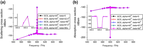
The SCS and ACS curves for fixed α = + 22.5°, +45°, and +67.5° and sweeping β are nearly the same as those in Figure . For example, as shown in Figure , there is only a slight decrease in the SCS peak value when α = + 45°. However, in all these cases, one significant difference is that a resonance is excited for all β angles since the tilt provided by these choices of α allows the incident plane a means to couple to the dominant electric dipole mode.
Figure 9 Cross sections obtained with α = 45° and by sweeping the angle β. (a) SCS, and (b) ACS values vs. frequency.
4.1.3 Sweeping the angle β when the angle α = 90°
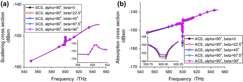
To confirm the earlier observation, when α = 90° and β varying, the plane wave does not couple well to the electric dipole mode in this orthogonal orientation. Only a small resonance response is observed in either the SCS or ACS results given in Figure .
Figure 10 Cross sections obtained with α = 90°, and by sweeping the angle β. (a) SCS, and (b) ACS values vs. frequency.
Comparing the results in , it is clear that the ACS and SCS values significantly depend on α, especially the peak value and the SCS background values, but depend only slightly on β.
4.2 Specific cases
4.2.1 Results for the case with l = 31.5 nm, r1 = 15.5 nm, dd = 6 nm, α = 22.5°, and β = 0°
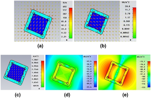
Because the incident electric field is taken to be parallel to the Z axis, the angle α = + 22.5° means that the electric field vector, the incident wave vector, and the axis of the active C-CNP all lie in a single plane. The angle between the incident electric field vector and the axis of the cylindrical particle is α. This means the input electric field can be divided into two orthogonal parts relative to the cylinder axis: E// and E⊥. The component E// is parallel to the cylinder axis, which is the same as the parallel polarization wave case given by [Figure , Citation34]. The component E⊥ is perpendicular to the cylinder axis; it excites the Et polarization component. Although the E⊥ component induces a new polarization for the scattered field, E// is still the dominant component at 600.05 THz, the resonance frequency. Various quantities are depicted in Figure at the resonance frequency. The electric fields in the shell and in the core in Figure are mainly parallel to the axis of the active C-CNP. The power flow in Figure is mainly perpendicular to the axis of the active C-CNP, strongly flowing outward away from the core. It is almost symmetrical with respect to the cylinder axis. The current density in Figure is flowing nearly parallel to the cylinder axis. The electric and magnetic field energy densities in Figure reveal the dipole mode relative to the cylinder axis is dominant. This observation is reaffirmed by the results shown in Figure .
Figure 11 Distributions for α = 22.5° and β = 0°, at the resonance frequency 600.05 THz for the vertical polarized incident plane wave. (a) Electric field; (b) power flow; (c) current density; and (d) electric and (e) magnetic field energy density.
4.2.2 Results for the case with l = 31.5 nm, r1 = 15.5 nm, dd = 6 nm, α = 45°, and β = 45°
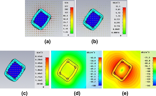
The incident electric field remains parallel to the Z axis, but with the cylinder now oriented with α = 45° and β = 45°. The incident electric field vector is thus no longer lying in the same plane as the cylinder axis. Nevertheless, the incident electric field vector can be decomposed into three orthogonal parts relative to that axis: E// to the cylinder axis and E⊥ in the plane perpendicular to it. The component E// results are again the same as the case given by [Figure , Citation34]. The components of E⊥ excite the Ey and Et polarization behaviors shown previously in . Nonetheless, the various distributions of the field, power flow, current density and electric and magnetic field energy densities shown in Figure at the resonance frequency, 600.05 THz, illustrate that the E// component is still dominant. The E fields in the shell and in the core are mainly parallel to the axis of the active cylindrical particle. The power flow remains mainly perpendicular vertical to the axis of the active C-CNP. The electric and magnetic field energy densities show that the electric dipole mode relative to the cylinder axis dominates the local field behaviors.
Figure 12 Distributions at the resonance frequency 600.05 THz for the vertically polarized incident plane wave incident on the active C-CNP with α = 45° and β = 45°. (a) Electric field; (b) power flow; (c) current density; and (d) electric and (e) magnetic field energy density.
5 Conclusions
An investigation of the polarization-dependent scattering properties of a set of active cylindrical coated nano-antennas in the visible frequency band was presented. It was discussed how the plane wave excitation of an arbitrarily oriented active C-CNP can be decomposed into its excitation by three different plane waves whose polarizations are orthogonal. It was shown how the active C-CNP radiates in a dipole mode for each of these polarization states and has similar scattering and absorption characteristics even though its resonant size is slightly different for each case. Results for different angles of incidence were given. These results were used to explain how the fields radiated by an active C-CNP and, hence, the peak and background values of the SCS and ACS results depend on the relative orientation of the polarization vector and the cylinder axis. Furthermore, it was demonstrated that an active C-CNP excited by a plane wave with arbitrary polarization responds in a dipole mode which is dominated by the contributions from the polarization component oriented along the central axis of the cylinder.
Acknowledgments
The work was supported in part by “973” (2009CB320403); the Research and innovation project of the Shanghai Education Commission (12Z112030001); the National Natural Science Foundation (61201058); the Doctoral Fund of Ministry of Education of China (20090073120,033); the National Science and Technology of major projects (2011ZX03001-007-03); Scientific Research Foundation for Returned Scholars, Ministry of Education of China; and by ONR Contract number H940030920902.
Related Research Data
References
- Jain, PK, Huang, X, El-Sayed, IH, and El-Sayed, MA, 2008. Noble metals on the nanoscale: optical and photo thermal properties and some applications in imaging, sensing, biology, and medicine, Acc. Chem. Res. 41 (2008), pp. 1578–1586.
- Liu, X, and Huo, Q, 2009. A washing-free and amplification-free one-step homogeneous assay for protein detection using gold nanoparticle probes and dynamic light scattering, J. Immunol. Methods. 349 (2009), pp. 38–44.
- García-Cámara, B, Moreno, F, González, F, and Martin, OJF, 2010. Light scattering by an array of electric and magnetic nanoparticles, Opt. Express. 18 (2010), pp. 10001–10015.
- Catchpole, KR, and Polman, A, 2008. Plasmonic solar cells, Opt. Express 16 (2008), pp. 21793–21800.
- Kawata, S, Inouye, Y, and Verma, P, 2009. Plasmonics for near-field nano-imaging and superlensing, Nat. Photonics. 3 (2009), pp. 388–394.
- Guillaumée, M, Dunbar, LA, Santschi, Ch, Grenet, E, Eckert, R, Martin, OJF, and Stanley, RP, 2009. Polarization sensitive silicon photodiodes using nanostructured metallic grids, Appl. Phys. Lett. 94 (2009), pp. 193503-1–193503-3.
- Gordon, JA, and Ziolkowski, RW, 2007. The design and simulated performance of a coated nano-particle laser, Opt. Express. 15 (2007), pp. 2622–2653.
- Averitt, RD, Westcott, SL, and Halas, NJ, 1999. Linear optical properties of gold nanoshells, J. Opt. Soc. Am. B. 16 (1999), pp. 1824–1832.
- Gordon, JA, and Ziolkowski, RW, 2008. Colors generated by tunable plasmon resonances and their potential application to ambiently illuminated color displays, Solid State Comm. 146 (2008), pp. 228–238.
- Gordon, JA, and Ziolkowski, RW, 2008. Investigating functionalized active coated nanoparticles for use in nano-sensing applications, Opt. Express. 15 (2008), pp. 12562–12582.
- Arslanagić, S, and Ziolkowski, RW, 2010. Active coated nano-particle excited by an arbitrarily located electric Hertzian dipole – resonance and transparency effects, J. Opt. 12 (2010), pp. 024014-1–024014-9.
- De Luca, A, Grzelczak, MP, Pastoriza-Santos, I, Liz-Marzán, LM, La Deda, M, Striccoli, M, and Strangi, G, 2011. Dispersed and encapsulated gain medium in plasmonic nanoparticles: a multipronged approach to mitigate optical losses, ACS Nano. 5 (2011), pp. 5823–5829.
- Noginov, MA, Zhu, G, Belgrave, AM, Bakker, R, Shalaev, VM, Narimanov, EE, Stout, S, Herz, E, Suteewong, T, and Wiesner, U, 2009. Demonstration of a spaser-based nanolaser, Nature. 460 (2009), pp. 1110–1113.
- Gordon, JA, and Ziolkowski, RW, 2008. CNP optical metamaterials, Opt. Express. 16 (2008), pp. 6692–6716.
- Strangi, G, De Luca, A, Ravaine, S, Ferrie, M, and Bartolino, R, 2011. Gain induced optical transparency in metamaterials, Appl. Phys. Lett. 98 (2011), pp. 251912-1–251912-3.
- Campione, S, and Capolino, F, 2011. Complex modes and near-zero permittivity in 3D arrays of plasmonic nanoshells: loss compensation using gain, Opt. Mat. Express. 1 (2011), pp. 1077–1089.
- Campione, S, and Capolino, F, 2012. Composite material made of plasmonic nanoshells with quantum dot cores: loss-compensation and ϵ-near-zero physical properties, Nanotechnology. 23 (2012), pp. 235703-1–235703-6.
- Klar, TA, Kildishev, AV, Drachev, VP, and Shalaev, VM, 2006. Negative-index metamaterials: going optical, IEEE J. Sel. Topics Quantum Electron. 12 (2006), pp. 1106–1115.
- Xiao, S, Drachev, VP, Kildishev, AV, Ni, X, Chettiar, UK, Yuan, H-K, and Shalaev, VM, 2010. Loss-free and active optical negative-index metamaterials, Nature. 466 (2010), pp. 735–738.
- Geng, J, Ziolkowski, RW, Jin, R, and Liang, X, 2011. Numerical study of near-field and far-field properties of active open cylindrical coated nano-particle antennas, IEEE Photonics J. 3 (2011), pp. 1093–1110.
- Desurvire, E, 1990. Study of the complex atomic susceptibility of erbium-doped fiber amplifiers, J. Lightwave Tech. 8 (1990), pp. 1517–1527.
- Kerker, M, 1978. Resonances in electromagnetic scattering by objects with negative absorption, Appl. Opt. 18 (1978), pp. 1180–1189.
- Ziolkowski, RW, and Kipple, AD, 2005. Reciprocity between the effects of resonant scattering and enhanced radiated power by electrically small antennas in the presence of nested metamaterial shells, Phys. Rev. E. 72 (2005), pp. 036602-1–036602-5.
- Alú, A, and Engheta, N, 2005. Achieving transparency with plasmonic and metamaterial coatings, Phys. Rev. E. 72 (2005), pp. 016623-1–016623-9.
- Geng J, Ziolkowski RW, Jin R, Liang X. Detailed performance characteristics of vertically polarized, cylindrical, active coated nano-particle antennas. Radio Sci. 47, RS2013, 2012. doi:10.1029/2011RS004898..
- Arslanagić, S, Liu, Y, Malureanu, R, and Ziolkowski, RW, 2011. Impact of the excitation source and plasmonic material on cylindrical active coated nano-particles, Sensors. 11 (2011), pp. 9109–9120.
- Arslanagić, S, 2012. Power flow in the interior and exterior of cylindrical coated nanoparticles, Appl. Phys. A. 109 (2012), pp. 921–925.
- Wang, H, Brand, DW, Le, F, Nordlander, P, and Halas, NJ, 2006. Nanorice: a hybrid plasmonic nanostructure, Nano Lett. 6 (2006), pp. 827–832.
- Khajavikhan, M, Simic, A, Katz, M, Lee, JH, Slutsky, B, Mizrahi, A, Lomakin, V, and Fainman, Y, 2012. Thresholdless nanoscale coaxial lasers, Nature. 482 (2012), pp. 204–207.
- http://www.cst.de/Content/Company/Academic.aspx.
- Weiland, T, 1998. Time domain electromagnetic field computation with finite difference methods, Int. J. Numer. Model. EL. 9 (1998), pp. 259–319.
- Johnson, PB, and Christy, RW, 1972. Optical constants of the noble metals, Phys. Rev. B. 6 (1972), pp. 4370–4379.
- Saleh, BEA, and Teich, MC, 1991. Fundamentals of photonics. Hoboken, NJ: Wiley; 1991.
- Geng J, Ziolkowski RW, Jin R, Liang X. Studies of a nanometer antenna combined with open and closed cylindrical active coated nano particles. In: Proc. 2012 IEEE International Symposium on Antennas and Propagation; July 2012; Chicago, IL; paper IF53.2..