
 ?Mathematical formulae have been encoded as MathML and are displayed in this HTML version using MathJax in order to improve their display. Uncheck the box to turn MathJax off. This feature requires Javascript. Click on a formula to zoom.
ABSTRACT
In the last decade, it has been shown that short-range ultra-wideband (UWB) sensors can provide promising solutions to the issue of people localization in many interesting applications. The applicability of particular localization methods utilizing this wireless technology depends on the form of the motion of the monitored person. Therefore, great effort was initially taken to localize people who always carry out the same type of movement, i.e. to localize either moving or only static persons. In real life, people do not move always by the same form of the motion, but the character of their movement is normally time-variable. Moreover, a person-monitoring system has usually no a priori information about the movement status of the person to be monitored. The issue of localization of persons moving both by an unknown and changing character of motion has not been satisfactorily addressed. Motivated by these findings, we will introduce a new concept of UWB sensor signal processing focused on localization of a person moving with an unknown and time-variable character of motion. This concept is based on the decomposition of possible motion activities of persons into a finite set of basic forms of movement defining the so-called types of persons, while a specific signal processing procedure is proposed. The corresponding form of a person's movement is first identified and then the person is detected and localized. The performance properties of this concept will be illustrated by its application for through-the-wall localization of a person moving with short and long stops.
1. Introduction
Developments in sensing technology have shown that UWB sensors (radars) are becoming increasingly valuable sensing devices that can be used to monitor human activity in both military/police and civilian areas. This interest has been motivated by their unique features such as their high-range resolution and ability to localize people not only for line-of-sight (LOS) scenarios but also persons hidden behind visually opaque structures, e.g. building walls. On the other hand, technological advancements in the field of design and manufacture of integrated circuits and antennas have allowed the implementation of UWB sensors in the form of a system-in-package (SiP) [Citation1–3]. This has resulted in two positive trends. The former is the fact that the mentioned radars can be constructed to be light-weight, small-sized, and low-energy consumption and hence flexibly useable in a real operation area. On the other hand, the potential implementation of UWB sensors such as SiP, in turn, creates space for lowering the prices of UWB sensors. These findings have stimulated the extensive development of many interesting applications of UWB sensors. They include person localization (e.g. search and rescue missions in natural disaster, crisis scenario management [Citation4,Citation5], ambient assisted living programs – elderly person monitoring in their dwellings [Citation6,Citation7], etc.), person activities monitoring (e.g. car driver monitoring [Citation8], person gesture or posture recognition [Citation9,Citation10], estimating the number of people in a monitored area (so-called people counting) [Citation11], etc.), contactless monitoring of vital signs of persons by biometric radars (breathing and heart beating) (e.g. [Citation6,Citation12–14]), etc.
People localization belongs undoubtedly among the oldest applications of UWB sensors. In this field, attention has been devoted to the localization of people for LOS scenarios [Citation15], through-a-vertical wall [Citation16] and through-the-floor localization of people [Citation17], and finally, locating people around a corner [Citation18]. As sensor systems, multistatic UWB radars employing 1 transmitting (Tx) and at least 2 receiving antennas (Rxs) or UWB sensor networks have been considered for these scenarios. Note that the architecture and complexity of the UWB sensor system has a great impact on the total robustness and accuracy of the localization system performance.
Deeper analyses of the issue of people-monitoring using UWB sensors has shown that a key challenge to be addressed in this area is the processing of raw radar signals to detect and locate persons moving with different forms of motion [Citation19,Citation20]. From this point of view, the researchers' attention has been devoted to two fundamental directions. The former is focused on the localization of moving persons (MP), i.e. persons moving within the monitored area in such a way that their coordinates are changing. The latter approach is intent on the localization of static persons (SP), i.e. persons situated, but not moving within the monitored area (e.g. unconscious persons). As follows from such a definition of SP, the coordinates of SP are not changing. Note that respiration motions are usually the only visible form of SP movement. As a result of the researchers' effort, a whole range of signal processing methods for the localization of either MP or SP have been developed e.g. in [Citation21,Citation22].
Unfortunately, the form of a person's motion is not usually a priori known. Moreover, the people to be monitored are usually neither perfectly moving nor perfectly static ones (e.g. a person walking with short stops, a standing but gesturing person, a sleeping person changing its position, etc.). These findings indicate that there is a request to develop methods allowing for location of people changing the nature of their movements (MP-SP).
According to our best knowledge, there are only a few papers (e.g. [Citation19,Citation20,Citation23]) studying this issue. The concept of the MP-SP localization presented in the papers [Citation20,Citation23], referred to as “basic concept”, consists of a parallel application of algorithms for MP and SP localization. Then, the coordinates of the detected and localized MP and SP are mapped into the joint information space (e.g. a picture visualizing positions of human targets detected in a monitored area). Unfortunately, the basic concept of MP-SP localization according to [Citation20,Citation23] does not solve satisfactorily some specific but often occurring situations that may arise in real situations. For example, the detection and localization of a person walking or running with short stops cannot be successfully processed by the basic concept.
Motivated by these findings, we would like to present in this paper a new concept of UWB radar signal processing devoted to people localization by M-sequence UWB sensors. Its basic idea has been outlined in [Citation19]. The mentioned concept is based on the decomposition of possible movement activities of persons to the final set of basic forms of their motion. Then, in the process of the person localization, the corresponding form of person motion (or so-called person type) is detected firstly and then, based on this finding, the person is localized. Unlike the basic concept, this new approach is capable of detecting and localizing MP, SP, and MP-SP including a person moving with short stops. For this purpose, a variance of radargram with subtracted background evaluated along the fast-time-axis will be applied as the indicator of a short stop of MP.
This paper is organized as follows. In the next section, the basic principles of person detection using UWB sensors will be summarized. Note that M-sequence UWB radar (e.g. [Citation24]) will be considered as a UWB sensor throughout this paper. The core of the paper (Section 3) will be devoted to a new concept of radar signal processing to be applied to MP, SP, and MP-SP localization. Moreover, a new signal processing scheme allowing for detection and localization of a person moving with an unknown character of his/her motion will be introduced in this chapter as well. Some experimental results illustrating the performance of the proposed localization approach will be shown in Section 4. In the last section, some concluding remarks will be summarized.
2. Basic principles of person detection
In the case of a person monitoring by using e.g. impulse of M-sequence UWB sensors, raw radar signals (data) gathered by such sensors are represented by a set of the impulse responses of the environment, through which the electromagnetic waves emitted by the radar are propagated from transmitting to receiving radar antenna. This set of impulse responses is usually referred to as a radargram. In this paper, the radargram will be denoted as , where t and τ are set for the propagation time (fast-time) and observation time (slow-time), respectively. Periods of sampling along the axes t and τ will be denoted as
and
, respectively.
The raw radar signals defined in this way can be modelled by the expression
(1)
(1) where
,
,
,
,
, and
represent signal emitted by the radar, radar echo, noise generated by receiving antenna and an analog front-end of the radar receiver, clutter, interference, and jamming, respectively. The operator
represents the input-output model of an analog front–end of a radar receiving channel. Note that signals
,
,
,
, and
are usually received by a radar receiving antenna at a standard operation of any radar systems.
On the other hand, the signal is transmitted by a radar transmitter in the form of electromagnetic waves, which are propagating in the environment surrounding the transmitting antenna. Then the radar echo
is a signal due to the portion of the energy of those transmitted electromagnetic waves which have been reflected by a target and which have been subsequently received by a radar receiver.
Unfortunately, in the case of UWB radars, the radar echo thus defined can be due to electromagnetic wave multipath propagation very complex. In this case, the Saleh-Valenzuela (S-V) model is usually used to characterize an impulse response of the UWB channel [Citation25–27]. One of the main characteristics described by that model is that electromagnetic waves propagating along particular paths arrive at the receiving antenna in clusters. A cluster is defined as a group of multipath components with similar arrival times and exponentially decaying amplitudes. Note, that the first detected reflection of an electromagnetic wave from the target contained in the first received cluster (so-called direct path) is usually used to estimate the time-of-arrival (TOA) of the target. In the next, this component of the radar echo will be referred to as the main component of the radar echo. On the other hand, the indirect paths (reflections) situated in the second and further clusters can cause a ghost problem [Citation27]. Note that the radar echo components not including its main component mentioned above will be in the next referred to as a residual radar echo. To handle the outlined impact of multipath propagation of electromagnetic waves in the field of person monitoring using UWB sensors, several methods can be used. They include efficient methods of TOA estimation focused on the detection of the main component of the radar echo (e.g. trace connection method [Citation28]), track maintenance methods included in multiple target tracking systems (MTT) (e.g. [Citation29,Citation30]) that prevent to create a new track due to short-time ghosts, and finally, complex methods based on UWB transmission channel modelling potentially allowing identify the main and residual components of the radar echo (e.g. [Citation27]).
The effectiveness of UWB radar systems used to monitor people depends on its ability to detect people in the monitored area. Here we would like to note that detector performance can be described by the probability of target detection () vs. signal to noise ratio. Then, if we take into account the raw radar signal model according to (Equation1
(1)
(1) ),
will depend on the main component of the radar echo-to-noise and clutter and the residual radar echo ration (ENCR). And hence, a set of methods allowing to increase ENCR are applied firstly for raw radar processing.
Taking into account the origin of the noise , we can assume that it is a zero-mean stationary white Gaussian noise [Citation24]. Our experiences have shown that 20–30 radar scans of the area of interest per second are usually sufficient for person monitoring. However, the measurement rate of standard UWB radars is up to several hundred scans per second. Then, it is possible to reduce the noise level
and at the same time increasing the ENCR by a proper averaging of the radar scans originally measured by a high measurement speed.
The clutter can be defined as signals due to electromagnetic waves emitted by the radar and reflected from objects situated in the monitored area that is not the desired target (so-called ambient static clutter) and as well as signals obtained as the results of antenna coupling and impedance mismatch of the RF circuits of the radar device. To increase ENCR, several clutter-reduction methods have been proposed (e.g. [Citation29,Citation31], etc.).
In the case of the UWB sensors performance, interference and jamming can be usually modelled by narrowband signals situated in the frequency spectrum occupied by the UWB signals employed by UWB sensors. The performance of the M-sequence UWB sensor under the conditions of a narrowband interference has been studied in [Citation32]. It has been shown in this paper, that due to the application of the pulse compression using M-sequence, the narrowband interference is transformed into a white zero-mean Gaussian noise, and hence it contributes to decreasing of ENCR. Then, the impact of narrowband interference can be reduced by averaging of the radar scans. However, if the total power of the interference is high, the ENCR is too small to detect the target with a high . In this case, for the reduction of the
impact, a corresponding notch filter implemented before the pulse compression phase could be applied.
Our practical experiences with UWB radars have shown that that raw radar signals are very complex and ENCR due to the above mentioned effects is usually very low. And that is the reason why simple signal processing methods cannot be applied to localize persons directly. Instead, comprehensive radar signal processing procedures have to be used for any applications of UWB sensors in the field of people monitoring. These procedures should include usually three groups of signal processing algorithms. While the first group of such algorithms is usually aimed at increasing ENCR, the second group is focused on person detection. And the last one deals with the issue of localization of targets themselves.
The deeper analysis of the issue of detection and consequently the localization of persons by M-sequence or impulse UWB sensors has shown that the fundamental solution of this problem depends on the character of the motion of persons to be localized (e.g. [Citation19–24,Citation33]). The results of the analysis are reflected in Table . This table suggests a classification of the person types according to the character of their motion. Then, the detection of a person including his or her type according to Table should be the crucial issue to be addressed in the process of people localization. Let us go, therefore, to discuss basic principles of MP and SP detection firstly.
Table 1. Classification of types of person according to the form of their motion.
An analysis of MP echo has shown that such a signal represents significantly non-stationary components of the raw radar signals. Therefore, a basic principle of MP-I and MP-II detection consists in the detection of time changes of adjacent impulse responses of the radargram due to the non-stationarity of the target echo [Citation34]. The mentioned changes should be detected along the propagation time axis. It means that only two adjacent impulse responses measured by the radar are theoretically needed for the detection of MP. Therefore, the minimum length of the observation time interval for MP detection is , where
is sampling period along the observation time axis.
On the other hand, a basic principle of SP detection consists in the detection of the person's respiratory motions. It is well-known (e.g. [Citation6,Citation35,Citation36]), that human beings' respiration can be considered as a periodical process with a fundamental harmonic frequency , whereby the pick-to-pick value of the chest motion due to the respiration in adults is about 0.4–1.2 cm. If we neglect for a moment the small changes of the distance between the person's body and the radar antenna array due to respiration, then the monostatic/bistatic range of the person can be considered as the constant one. Then, SP can be detected based on the identification of periodical components of the radargram with a fundamental harmonic component from the frequency interval
for a constant monostatic/bistatic distance of the target and radar antenna array [Citation33]. And hence, an appropriate method of spectrum estimation of the radargram has to be applied to detect SP.
As follows from the spectrum analyses theory, a sufficiently long record of the signal should be used for its power spectrum estimation. For example, our practical experiences with SP localization based on the radargram power spectrum estimation employing Welch periodogram method (e.g. [Citation37]) have shown that is usually sufficient for SP detection. Therefore, this length of the observation time interval will be considered for the SP detection in this paper. Note that if
then the target probability detection is decreasing rapidly.
Following the above outlined basic principles of MP and SP detection, a new concept of person monitoring by M-sequence UWB sensor can be proposed. The basic features of this approach are introduced in the next chapter.
3. A new concept of person localization
The new concept of signal processing scheme focused on person localization using UWB sensors is based on the decomposition of possible movement activities of persons to the final set of basic forms of their motion. The mentioned set of basic forms of the motion of a person is used to define basic types of persons relevant for the solution of the issue of person localization. A classification of person types according to the form of their motion is shown in Table . Following this idea, in the person monitoring process, the corresponding type of person is first detected and then the person is localized and tracked by the corresponding procedure selected based on this finding. The particular steps of this approach focused on localization and tracking of a single person moving with an unknown type of motion are summarized in the signal processing scheme depicted in Figure . Later, this scheme will be described a bit more in detail.
Figure 1. Signal processing scheme for localization of a person moving with unknown type of motion.
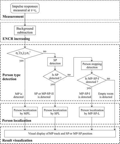
Let us assume that the impulse responses measured by the first and second receiving channels of the radar at the observation-time instant (raw radar signals) are the input signals of the considered signal processing scheme (Figure ). Because ENCR is usually very low for raw radar signals, the stationary background represented especially by clutter is firstly subtracted. For that purpose, a simple but very efficient method known as exponential averaging can be used to advantage (e.g. [Citation31]). According to this method, the background estimate
is obtained by
(2)
(2) where α is a constant weighting factor setting the length of background estimator memory. Then, the radargram with a subtracted background can be obtained by the expression
(3)
(3) By the application of the background subtraction method, the impulse responses with the subtracted background
will be obtained. Later, we will assume that the set of
for
will be available to be applied to the target detection.
Since it is usually not known a priori whether there is MP or SP in the monitored area or whether the monitored area is empty, it is necessary to detect a person's type according to Table in the next step. For that purpose, monitoring of the variance of the impulse responses with the subtracted background can be employed. The mentioned variance can be estimated for the observation-time instant
as
(4)
(4) where
(5)
(5) is the mean of
for
.
As will be illustrated in the next section, possesses a very useful property. If MP is in the monitored area at the time of observation
, then
is relatively high. On the other hand, if
is relatively small, then no MP is located in the monitored area at
. Then it is obvious that
could be employed to detect the presence or absence of MP in the monitored area using the following simple algorithm.
Firstly, the variance of
is estimated according to (Equation4
(4)
(4) ) and (Equation5
(5)
(5) ). As will be shown in the Section 4, the variances
contain not only slowly changing DC component, but also noise components. Then, to smooth
, it is filtered by a median filter, what is formally expressed as follows:
(6)
(6) Now, let us define a variance range as
(7)
(7) Then MP is detected in the monitored area at the observation time instant
, if
(8)
(8) where
is the variance threshold set to
of the variation range given by (Equation7
(7)
(7) ). On the other hand, if
(9)
(9) then no MP is located in the monitored area for
.
If MP is detected by (Equation8(8)
(8) ) for
, then moving person detection, localization, and tracking (MPL) can be used for person localization. On the other hand, if (Equation9
(9)
(9) ) is held, SP could be detected and localized by static person detection and localization (SPL) for
. And finally, if (Equation9
(9)
(9) ) is held and SP is not detected, then MP-SP-I could be situated in the monitored area, or monitored area is empty. MPL, SPL, and the detection and localization MP-I and MP-II will be discussed in the next paragraphs of this Section.
We would like to note that the level of variance depends on the level of signal components obtained due to the reflection of electromagnetic waves from the target and on the ENCR. Because the relative level of the radar echo of the MPs is higher than in the case of SPs or an empty room,
is also higher for MPs than for SPs or an empty room. However, the absolute power of the radar echo depends also on transmitted power, the distance between the target and radar antenna array, on the antenna gain and aperture, and finally on the radar cross-section. The relation among these parameters is expressed by the radar range equation [Citation38]. Then if the distance between the target and radar antenna array would be large and at the same time ENCR would be low, it could happen, that the level of
would be low for MP detection also, and hence the signal processing scheme shown in Figure would not perform correctly.
The outlined possible incorrect performance of the detection of the motion state of the monitored person is limited by two factors. Firstly, the threshold used in (Equation8
(8)
(8) ) and (Equation9
(9)
(9) ) is adaptively changing and at the same time does not depend directly on the absolute values of variance
but the percentage level of the variation range. As a result, if the
is decreased due to a large distance between the target and radar antenna array but if ENCR is high enough the threshold
will be also decreased, and the detection of the motion state of the monitored person should be correct. On the other hand, if ENCR is low, then (Equation8
(8)
(8) ) may not apply even for MP. However, if ENCR is small, the probability of target detection
will be low as well, and a target will not be detected with a high probability. However, under such circumstances, the issue of detection of motion state of a not detected person is irrelevant. Therefore, we can assume that if the ENCR is high enough to detect MP, then the detection of the motion state of the monitored person will be correct. On the other hand, if ENCR is not high enough, the primary problem to be solved is increasing of ENCR level.
3.1. Moving person localization and tracking
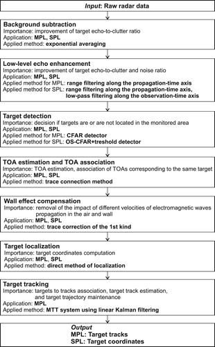
For the detection and localization of MP-I and MP-II, the radar signal processing procedure for MPL has been proposed in [Citation21]. According to this article, MPL consists in the principle of the set of seven basic signal processing phases such as background subtraction, target echo enhancement, target detection, time of arrival (TOA) estimation (including TOA association), wall effect compensation, target localization, and target tracking (Figure ) [Citation16]. For the implementation of these phases, exponential averaging method (background subtraction phase) [Citation31], range filtering (target echo enhancement) (e.g. [Citation39,Citation40]), constant false alarm rate (CFAR) detection (target detection phase) [Citation41], trace connection method (TOA estimation phase) [Citation28], trace correction of the first kind or second (wall effect compensation) [Citation42,Citation43], direct computation (target localization phase) [Citation44], and multiple target tracking (MTT) system (target tracking phase)[Citation29,Citation30] are recommended. As can be seen in Figure , the background subtraction has been applied as the first step of the signal processing scheme shown in Figure . Therefore, this phase does not have to be used again in the MPL employed according to Figure . Note also, that the wall effect compensation phase should be implemented only for through-the-wall person localization. The mentioned methods (especially CFAR, trace connection method, direct computation, MTT system) are too complex to be described in this paper deeply using a set of expressions and/or flow-charts. Therefore, a more detailed discussion of the MPL is unfortunately beyond the scope of this paper. Additional information concerning this topic can be found e.g. in [Citation21,Citation29].
Figure 2. Block diagram of MPL and SPL.
3.2. Static person localization
For SP localization, the radar signal processing procedure for SPL introduced in [Citation22] can be used. In contrast to MPL, SPL considered in this paper consists of six basic phases of signal processing which include background subtraction, target echo enhancement, target detection, TOA estimation, wall effect compensation, and target localization (Figure ). For the implementation of these phases, exponential averaging method (background subtraction phase) [Citation31], range filtering along the propagation-time axis (e.g. [Citation45,Citation46]) and low-pass filtering along the observation-time axis (target echo enhancement phase) [Citation22], trace connection method (TOA estimation phase) [Citation28], trace correction of the first kind or second (wall effect compensation) [Citation42,Citation43], and direct computation method (localization phase) [Citation44] have been proposed. For SP detection, a two-stage detector consisting of a power spectrum estimator (implemented e. g. by Welch periodogram method [Citation47]) [Citation22], order statistics CFAR detector (OS-CFAR) [Citation48] and simple threshold detector [Citation22] can be applied. Similarly to as in the case of MPL, its background subtraction phase has been applied also in the case of SPL as the first step of the signal processing scheme shown in Figure . Therefore, this phase need not be reused in the SPL applied according to Figure . Because of the complexity of most of the methods employed by SPL (especially OS-CFAR, Welch periodogram computation, trace connection method, and direct computation, etc.), a deeper discussion and description of SPL are also beyond this paper. Some useful details concerning the SPL can be found e.g. in [Citation22].
3.3. Localization of person changing nature of his or her movement
Let us consider the detection and localization of MP-SP-I and MP-SP-II. The method of determining the position of the person depends on whether the person is detected at the observation-time as MP or SP. If the person to be detected in the observation time
is in the role of MP, he or she can be detected and localized by MPL. If the person to be detected in the observation-time
is in the role of SP and
s (MP-SP-II), he or she can be detected and localized by SPL. On the other hand, if the person to be detected in the observation time
is in the role of SP and
s (MP-SP-I), then such a person will be neither detected by SPL nor by MPL. Then, to get some estimate of the position of such a person, one can employ the following procedure. Firstly, the time instant of the stopping of the person will be found. Then, the person's coordinates at the instant in time of his or her stopping will be computed by MPL. In the next instants in time, the person is in the role of SP. In this case, the estimate of his or her coordinates will be equal to his or her coordinates estimated for the instant in time of his or her stopping. In the next, the described algorithm of MP-SP-I localization will be referred to as a radar signal processing procedure for MP-SP localization (MP-SP-L). Note, that if no MP or SP is detected, then the monitored area is empty.
3.4. Localization of person moving with unknown type of motion
In the previous paragraphs of this section, we have proposed signal processing procedures for MP, SP, and MP-SP localization. Unfortunately, the person-monitoring system does not usually know the type of person to be localized. Therefore, for real-life scenarios, a signal processing scheme allowing localization of a person moving with an unknown type of motion is needed. Such a scheme is shown in Figure . We can see from this figure that it consists of the earlier described algorithms of the detection of the person's type which are followed by corresponding radar signal processing procedures. As the final step of the considered signal processing scheme, the results of these procedures expressed by the coordinates and/or track of the target are appropriately visualized.
4. Experimental results
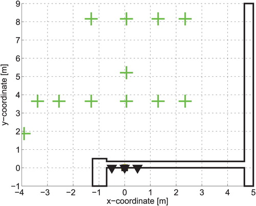
The performance of the introduced signal processing scheme proposed for monitoring of a person moving with the unknown and changing character of movement has been experimentally tested for through-the-wall localization of a single person (in the next “experimental scenario”). The measurement scheme is shown in Figure . The specific positions (P) of the person to be monitored in the experimental scenario can be split into the following nine phases:
| A. | The person entered the empty room through the position P11. | ||||
| B. | The person walked along the trajectory P11-P10-P9-P6-P1-P3-P5. | ||||
| C. | The person was sitting on a chair situated at the position P5 for about 30 s. | ||||
| D. | The person stood up. Then the person walked along with the positions P5-P8-P9-10-P11. Finally, the person left the monitored area through the position P11. | ||||
| E. | The monitored area remained empty for about 10 s. | ||||
| F. | The person entered the empty room again through the position P11. Then the person walked along the trajectory P11-P10-P9-P8-P5. Finally, at position P5, the person sat on a chair. | ||||
| G. | The person was sitting on the chair (position P5) for 30 s. | ||||
| H. | The person stood up and then walked along the trajectory P5-P8-P9-P10-P11. | ||||
| I. | The person left the monitored area through the position P11. | ||||
Figure 3. The measurement scheme of the experimental scenario. The particular distances are in the unit of cm.
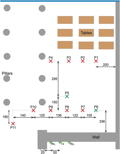
The person was monitored by a multistatic M-sequence UWB radar system (Figure ) [Citation24,Citation49]. The radar antenna array consisted of one transmitting (Tx) and two receiving antennas (Rx). The parameters of the radar and the antennas are summarized in Table . The antenna array layout and its position are outlined in Figure . The radar system was situated behind a brick wall with a thickness of 0.5 m. Note that the base of the coordinate system is situated at the position of Tx. The total measurement time was 115 s. The particular coordinates of the monitored person were estimated by the methods described in the previous section. The obtained results are shown in Figures .
Figure 4. UWB radar system.
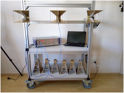
Figure 5. Raw radar signals (radargram). The first receiving channel.
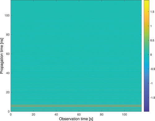
Table 2. UWB radar system parameters.
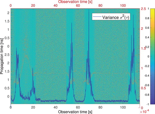
The raw radar signals measured by the described UWB radar system were processed by the signal processing scheme outlined in Figure . According to this scheme, the stationary background was firstly subtracted using the exponential averaging method. Then the algorithm detecting changes in the movement status of the monitored person was applied. The raw radar signals (i.e. so-called radargram), the radargram with the subtracted background, and the variances of the particular impulse responses computed by (Equation4
(4)
(4) ) and (Equation6
(6)
(6) ) (all for the first receiving channel) are depicted in Figures and , respectively. As is visible from Figure , the values of the variance
are relative high, if the person was moving. On the other hand, the values of this variance are relatively small, if the person was sitting on the chair or if the monitored room was empty. Note that similar results can be achieved for the second receiving channel.
Figure 6. Radargram with subtracted background, variances of the impulse responses.
The variances and the filtered variances
of the particular impulse responses computed by (Equation4
(4)
(4) ) and (Equation6
(6)
(6) ), as well as the variance threshold defined by (Equation8
(8)
(8) ) are shown in Figure . Comparing the filtered variance and variance threshold (expressions (Equation8
(8)
(8) ) and (Equation9
(9)
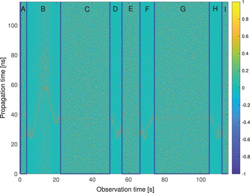
(9) )), eight changes were detected in the movement status of the monitored person (Figure ). As we can observe from this figure, the detected statuses of the motion of the person correspond very well with the particular phases of the person's motion (denoted from A to I) specified at the beginning of this section.
Figure 7. The variances , the filtered variances
, and the variance treshold
.
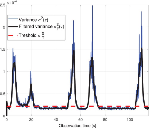
Figure 8. Radargram with the subtracted background with labelling of the particular phases of the person's motion.
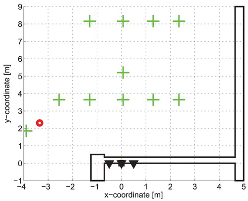
The results of the person-monitoring obtained by the application of this approach are presented in Figures –. In these figures, we can see several kinds of symbols. There are large green “plus symbols”, small red and small blue “plus symbols”, and large dark-green and large blue “plus symbols”. These last two symbols are situated inside of a circle. The large green “plus symbols” indicate the positions P1–P11. The small red and blue “plus symbols” represent the results of the phase of the target localization. The red “plus symbols” corresponds to the estimated positions of the monitored person if he or she is in the role of MP. Note that many of the “red plus symbols” (i.e. the estimated positions of the target) are overlapped by the estimated target track (thick red curve consisting of a set of large thick red circles e.g. in Figure ). On the other hand, the blue “plus symbols” corresponds to the positions of false alarms due to a low level of ENCR and/or electromagnetic wave multipath propagation. Note, that the impact of these false alarm has been suppressed by the MTT system, and hence no further track has been created.
Figure 9. Person monitoring results for the A phase of person motion (empty room).
And finally, the dark-green and blue “plus symbols” situated inside of a circle (Figures , ) represent the true and estimated position of the monitored person if he or she is in the role of SP. The circle with the center in the true position of the target with a radius of 0.4 m represents the so-called tolerance area for SP estimation. Because the size of the tolerance area is comparable with the size of SP (approximately chest diameter), it is clear that if the estimated position of SP is situated inside of the tolerance area, then the accuracy of SP localization can be considered very good. Besides the mentioned symbols, we can see in Figures , , and also a planar strip drawn around the specific positions P indicating the true track of the target if he is in the role of MP. The width of this planar trip is 0.7 m, which corresponds to the size of the MP (span between the left and right hand of MP). Then this planar trip represents a tolerance area that can be applied for an evaluation of the accuracy of the MPL. The importance of the tolerance area for MP is the same as that of SP. I.e. if the estimated position of MP is situated inside of the tolerance area then the accuracy of MP localization can be considered as very good. Let us assume that an estimate of the target position is situated inside of the mentioned tolerance areas including their borders. Then, such an estimate of the position of the target will be referred to as the correct localization of a target.
Figure 10. Person monitoring results for the B phase of person motion (MP trajectory estimated by MPL).
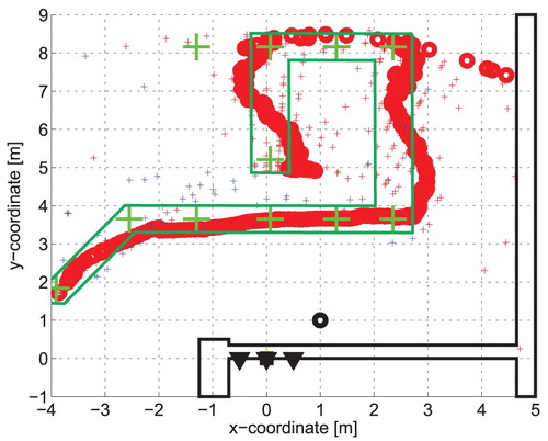
Figure 11. Person monitoring results for the C phase of person motion (SP position estimated by SPL).
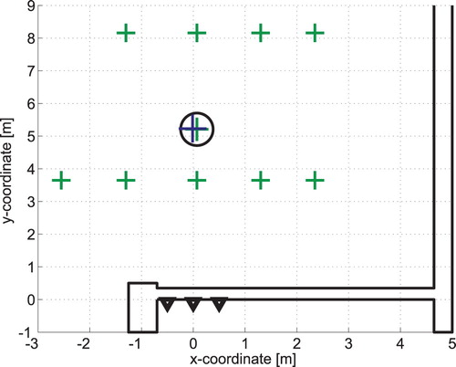
Figure 12. Person monitoring results for the D phase of person motion (MP trajectory estimated by MPL).
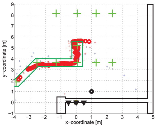
Figure 13. Person monitoring results for the E phase of person motion (MP-SP-I position estimated by MP-SP-L).
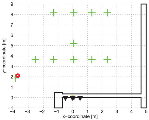
Figure 14. Person monitoring results for the F phase of person motion (MP trajectory estimated by MPL).
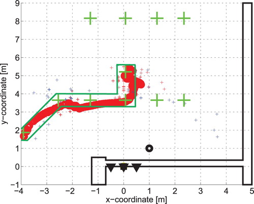
Figure 15. Person monitoring results for the G phase (SP position estimated by SPL).
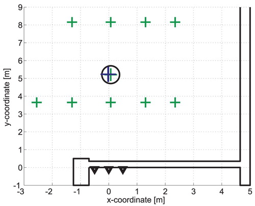
Figure 16. Person monitoring results for the H phase of person motion (MP trajectory estimated by MPL).
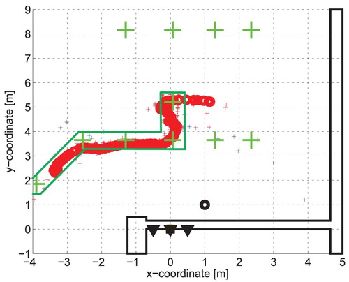
Figure 17. Person monitoring results for the I phase of person motion (MP-SP-I position estimated by MP-SP-L).
A simple visual inspection of Figures – showing estimates of a person's positions during the various phases of his monitoring, confirms that MPL, SPL, MP-SP-L and the proposed signal processing scheme according to Figure can detect the corresponding person's types (listed in Table ) as well as to follow the true track and the true positions of the monitored persons very well.
A slightly deeper look at the performance of these algorithms is provided in Table . In this table, a relative frequency of the correct detection of the person type (in percentage measure) and relative frequency of the correct localization of a target
(as well as in percentage measure) are given for the particular phases of the person monitoring for
. These two parameters have been computed as follows:
(10)
(10)
(11)
(11) where
,
and
are the number of correct detections of the person types within phase k, the number of correct localization of the person within phase k, and the total number of the impulse responses measured within the phase k, respectively. Moreover, the average value of these parameters given by
(12)
(12)
(13)
(13) are shown in Table as well. Note, that
and
express the average relative frequency of the correct detection of the person type
and the average relative frequency of the correct localization of a target
, respectively. Now, we can discuss the obtained results presented in Table . The values of parameters of
and
for a perfect operating monitoring system should be 100%. As follows from Table ,
is approaching this optimum value very well, if the person is in the role MP or SP. In these cases, some differences of
from its optimum value have origin especially in the transition regions, when the role of a person is changing. This situation is illustrated e.g. in Figure . A bit worse, but still well acceptable values of
have been obtained if the monitored room is empty, or if the monitored person is in the role of MP-SP-1. The performance of the person type detection algorithms for these parts of the experimental scenario could be explained by the fact that the level of the noise and clutter is relatively high, and hence
has been decreased.
Table 3. Quantitative analysis of experimental scenario results.
Relative frequency of the correct localization of a target is the best for the case when the monitored person is in the role of SP or if the room is empty. Slightly worse, but still very good results (around 90%) have been obtained for MP monitoring. The target tracks for these cases are shown in Figures , , and . It can be observed from these figures that target tracks come out from the tolerance area if the target is changing the direction of its motion, or if the target is changing his role from MP to SP. This behavior of the MTT has been expected and follows from the application of linear Kalman filters as the tracking filters of MTT. Some improvement of the MTT could be achieved if the linear Kalman filters would be replaced by filters allowing tracking of the maneuvering target e.g. by interacting multiple models (IMM) filters [Citation51].
The values of parameters and
are higher than 90%. These values indicate that the proposed scheme of the person detection type (Figure ), the MPL, SPL, and MP-SP-L could provide a good performance of a person monitoring. These expectations have been confirmed by Figures –.
5. Conclusion
In this paper, we have dealt with signal processing methods aimed at locating a person moving by an unknown and time-varying type of motion. A solution to this challenging issue presented in the form of a novel signal processing scheme focused on localization of a person moving with an unknown type of motion (Figure ) is based on the combination of the algorithm detecting the person type with MPL, SPL, and MP-SP-L. The core of the person type detection algorithm consists in the monitoring of the variance of the radargram with the subtracted background along the observation time axis. The results obtained for the experimental scenario have shown that this algorithm performs very well, while the proposed UWB radar signal processing scheme (Figure ) allows monitoring a person changing the character of his or her motion with good accuracy (Figures –).
The deeper analysis of the issue studied in the paper shows that the proposed signal processing scheme can provide good and robust performance only in the case of single-person localization. However, the signal processing scheme according to Figure can be used also for the localization of several persons if only MP and SP are located in the monitored area. Unfortunately, this algorithm in the presented form cannot be applied directly to multiple person localization moving with shortstops. For such scenarios, a new modification of the algorithm detecting a person moving with short stops has to be developed. In this case, the modification of the MTT system is necessary. It should be focused especially on the algorithm responsible for target tracks maintenance. In this case, the mentioned algorithm should solve the issue of point-to track-association where the particular points and tracks are represented by the results provided by MPL and SPL, respectively. A detailed solution to this task is beyond the scope of this article. It will be studied in our follow up research.
In this paper, we have focused on the issue of short-range UWB sensor applications for people monitoring. However, it is well known that such sensors can be used not only for monitoring of human beings but also for localization and tracking of some moving industrial objects. From this point of view, very good examples related to our paper can be found e.g. in [Citation52,Citation53]. In these papers, UWB sensors have been applied as a tool for the tracking of a crane [Citation52] or an industrial robot [Citation53]. In both cases, a single target moving with short or long stops has been localized and tracked. With regard to the similarity of the scenario studied in our paper and those considered in [Citation52,Citation53], we believe that the signal processing scheme proposed in our paper could be simply adapted also to localization and tracking of some types of moving industrial objects.
Disclosure statement
No potential conflict of interest was reported by the author(s).
Additional information
Funding
Notes on contributors
Mária Švecová
Mária Švecová was born in 1983 in Svidník, Slovak Republik. She received the Master of science degree in Mathematics from Pavol Jozef Šafárik University in Košice, Slovak Republik. She received the Ph.D. degree in Information Electronics from the Technical University of Košice, Slovak Republic. She is currently an Assistant Profesor with the Department of Mathematics and Informatics, Technical University of Košice, Slovak Republic. Her research interests include UWB radar signal processing with a focus on detection and tracking of persons moving behind obstacles as well as breathing detection and localization of motionless persons by UWB sensor and UWB sensor network.
Dušan Kocur
Dušan Kocur was born in 1961 in Košice, Slovakia. He received his Ing. (M.Sc.) and CSc. (Ph.D.) degrees in Radioelectronics from the Faculty of Electrical Engineering, Technical University of Košice, in 1985 and 1990, respectively. Now, he is the full professor at the Department of Electronics and Multimedia Communications of his Alma Mater. His research interests are radar signal processing, UWB technologies, and their applications. His research activities are intent on signal processing and sensor networks. In the field of sensors, he is focused on UWB sensors (radars) and short-range UWB sensor networks to be applied for detection, localization, and tracking of persons, on applications of UWB radars as biometric sensors (contactless measurements of human breathing frequency and his or her heart rate). Besides it, he deals with the issue of real-time operating UWB radar systems employed for the mentioned application fields.
References
- Zito D, Pepe D, Mincica M, et al. SoC CMOS UWB pulse radar sensor for contactless respiratory rate monitoring. IEEE Transactions on Biomedical Circuits and Systems. 2011 Dec;5(6):503–510.
- Kmec M, Helbig M, Herrmann R, et al. M-sequence-based single-chip UWB-radar sensor. In: Ultra-wideband, short-pulse electromagnetics 10. New York: Springer Science + Business Media; 2014. p. 453–461. Available from: https://ui.adsabs.harvard.edu/abs/2014use..book..453K.
- XETHRU X2; 2019. Available from: https://ui.adsabs.harvard.edu/abs/2014use..book..453K.
- Huffman C, Ericson C. Through-the-wall sensors for law enforcement: market survey. ManTech Advanced Systems International, Inc.; 2012. Available from: https://www.justnet.org/pdf/00-WallSensorReport-508.pdf.
- Huffman C, Hayes J, Ericson L. Through-the-wall sensors (TTWS) for law enforcement: test & evaluation. ManTech International Corporation; 2014. Available from: https://www.ncjrs.gov/pdffiles1/nij/grants/245944.pdf.
- Sachs J, Helbig M, Herrmann R, et al. Remote vital sign detection for rescue, security, and medical care by ultra-wideband pseudo-noise radar. Ad Hoc Netw. 2014;13:42–53. Available from: http://www.sciencedirect.com/science/article/pii/S1570870512001357.
- Diraco G, Leone A, Siciliano P. A radar-based smart sensor for unobtrusive elderly monitoring in ambient assisted living applications. Biosensors. 2017 Nov;7(4):55.
- Schires E, Georgiou P, Lande TS. Vital sign monitoring through the back using an UWB impulse radar with body coupled antennas. IEEE Trans Biomed Circuits Syst. 2018 Apr;12(2):292–302.
- Ahmed S, Khan F, Ghaffar A, et al. Finger-counting-based gesture recognition within cars using impulse radar with convolutional neural network. Sensors. 2019 Mar;19(6):1–14.
- Khan F, Leem SK, Cho SH. Hand-based gesture recognition for vehicular applications using IR-UWB radar. Sensors. 2017 Apr;17(4):1–18.
- Choi JW, Yim DH, Cho SH. People counting based on an IR-UWB radar sensor. IEEE Sens J. 2017 Sep;17(17):5717–5727.
- Anishchenko LN, Alekhin MD, Ivashov SI, et al. Bioradiolocation: methods and applications. Proceedings of The First International Aizu Conference on Biomedical Informatics and Technology (ACBIT 2013). Heidelberger Platz 3, Berlin, Germany, D-14197; 2014. (Communications in Computer and Information Science; 404).
- Baldi M, Cerri G, Chiaraluce F, et al. Non-invasive UWB sensing of astronauts' breathing activity. Sensors. 2015 Jan;15(1):565–591.
- Zhang Y, Chen F, Xue H, et al. Detection and identification of multiple stationary human targets via bio-radar based on the cross-correlation method. Sensors. 2016 Nov;16(11):1793.
- Rovňáková J, Kocur D. Short range tracking of moving persons by UWB sensor network. The 8th European Radar Conference (EuRAD 2011); Oct.; Manchester, UK; 2011. p. 321–324.
- Kocur D, Fortes J, Švecová M. Multiple moving person tracking by UWB sensors: the effect of mutual shielding persons and methods reducing its impacts. EURASIP J Wirel Commun Netw. 2017 Apr;68:1–15.
- Švecová M, Kocur D, Demčák J, et al. Through-the-floor localization of a static person by a multistatic UWB radar. Microw Opt Technol Lett. 2019;61(3):825–831.
- Zetik R, Eschrich M, Jovanoska S, et al. Looking behind a corner using multipath-exploiting UWB radar. IEEE Trans Aerosp Electron Syst. 2015 Jul;51(3):1916–1926.
- Kocur D, Švecová M, Novák D. UWB radar based localization of a person changing the nature of their motion state. 2018 International Conference on Radar (RADAR); Brisbane, QLD, Australia; Aug.; 2018. p. 1–6.
- Rovňáková J, Kocur D. UWB radar signal processing for positioning of persons changing their motion activity. Acta Polytech Hungar. 2013;10(3):165–184.
- Kocur D, Rovňáková J, Švecová M. Through wall tracking of moving targets by M-sequence UWB radar. In: Rudas IJ, Fodor J, Kacprzyk J, editors. Towards intelligent engineering and information technology. Berlin, Heidelberg: Springer; 2009. p. 349–364.
- Novák D, Švecová M, Kocur D. Multiple person localization based on their vital sign detection using UWB sensor. In: Goudos S, editor. Microwave systems and applications. InTech; London, United Kingdom; 2017.
- Kocur D, Novák D. UWB sensor based localization of person with the changing nature of his/her movement. Proceedings of the 2nd International Conference on Sensors Engineering and Electronics Instrumental Advances (SEIA'2016); Barcelona, Castelldefels, Spain; IFSA Publishing, S. L.; Sept.; 2016. p. 120–122.
- Sachs J. Handbook of ultra-wideband short-range sensing: theory, sensors, applications. Hoboken, NJ: John Wiley & Sons; 2013.
- Corrigan M, Walton A, Weihong N, et al. Automatic UWB clusters identification. IEEE Radio and Wireless Symposium;San Diego, California; 2009 Jan. p. 376–379.
- Saleh A, Valenzuela R. A statistical model for indoor multipath propagation. IEEE J Sel Areas Commun. 1987;5:128–137.
- Lee M, Lee J. Statistical modeling of indirect paths for UWB sensors in an indoor environment. Sensors. 2017;17(43):1–16.
- Rovňáková J, Kocur D. TOA estimation and data association for through-wall tracking of moving targets. EURASIP J Wirel Commun Netw. 2010 Aug;2010:1–11.
- Rovňáková J. Complete signal processing for through wall tracking of moving targets. LAP LAMBERT Academic Publishing, Germany; 2010.
- Blackman S, Popoli R. Design and analysis of modern tracking systems. Boston, London: Artech House; 1999.
- Zetik R, Crabbe S, Krajnak J, et al. Detection and localization of persons behind obstacles using M-sequence through-the-wall radar. Proc. SPIE 6201, Sensors, and Command, Control, Communications, and Intelligence (C3I) Technologies for Homeland Security and Homeland Defense V, Orlando, FL, USA; 62010I; May; 2006.
- Kocur D, Kazimir P, Hoffmann J. M-sequence UWB sensor signal degradation by narrowband signal. 2015 25th International Conference Radioelektronika (RADIOELEKTRONIKA); Pardubice, Czech Republic; 2015. p. 321–325.
- Kocur D, Švecová M. Signal processing for monitoring of static persons using UWB sensors: a survey. 2019 IEEE MTT-S International Microwave Biomedical Conference (IMBioC); Nanjing, China; Vol. 1; May; 2019. p. 1–3.
- Kocur D, Švecová M, Zetik M. Basic signal processing principles for monitoring of persons using UWB sensors – an overview. Acta Electrotech Inform. 2019 Apr;19(2):9–15.
- Lazaro A, Girbau D, Villarino R. Techniques for clutter suppression in the presence of body movements during the detection of respiratory activity through UWB radars. Sensors. 2014;14(2):2595–2618.
- Lazaro A, Girbau D, Villarino R. Analysis of vital signs monitoring using an IR – UWB radar. Prog Electromagn Res. 2010;100:265–284.
- Proakis J, Manolakis D. Digital signal processing: principles, algorithms, and applications. 3rd ed.Upper Saddle River, New Jersey, USA: Prentice Hall, Inc.; 1995.
- Skolnik M. Radar handbook. 2nd ed. McGraw-Hill Professional, USA; 1990.
- Nag S, Barnes M. A moving target detection filter for an ultra-wideband radar. Proceedings of the 2003 IEEE Radar Conference (Cat. No. 03CH37474); Huntsville, AL, USA; 2003. p. 147–153.
- Nag S, Fluhler H, Barnes M. Preliminary interferometric images of moving targets obtained using a time-modulated ultra-wide band through-wall penetration radar. Proceedings of the 2001 IEEE Radar Conference (Cat. No.01CH37200); Atlanta, GA, USA; 2001. p. 64–69.
- Dutta PK, Arora AK, Bibyk SB. Towards radar-enabled sensor networks. 2006 5th International Conference on Information Processing in Sensor Networks; Nashville, TN, USA; 2006. p. 467–474.
- Rovňáková J, Kocur D. Compensation of wall effect for through wall tracking of moving targets. Radioengineering. 2009 Jun;18(2):189–195.
- Thanh NT, van Kempen L, Savelyev TG, et al. Comparison of basic inversion techniques for through-wall imaging using UWB radar. 2008 European Radar Conference; Amsterdam, Netherlands; Oct; 2008. p. 140–143.
- Švecová M, Kocur D, Zetik R. Object localization using round trip propagation time measurements. 2008 18th International Conference Radioelektronika; Prague, Czech Republic; 2008. p. 1–4.
- Nezirovic A. Trapped-victim detection in post-disaster scenarios using ultra-wideband radar [dissertation]. Netherlands: Delft University of Technology; 2010.
- Nezirovic A, Yarovoy AG, Ligthart LP. Signal processing for improved detection of trapped victims using uwb radar. IEEE Trans Geosci Remote Sens. 2010;48(4):2005–2014.
- Proakis J, Manolakis D. Digital signal processing. Pearson Prentice Hall; 2007. Prentice Hall international editions; Available from: https://books.google.sk/books?id=H_5SAAAAMAAJ.
- Rohling H. Radar CFAR thresholding in clutter and multiple target situations. IEEE Trans Aerosp Electron Syst. 1983;AES-19:608–621.
- m:explore: M-Sequence System; Accessed: 2019-09-10. Available from: https://www.ilmsens.com/products/m-explore/.
- DRH10 Double ridget wavequide horn antenna; RF spin, s.r.o., 2019. Accessed: 2019-09-10. Available from: https://www.rfspin.cz/en/antennas/measurement-antennas/drh10.
- Kirubarajan T, Bar-Shalom Y. Kalman filter versus IMM estimator: when do we need the latter?IEEE Trans Aerosp Electron Syst. 2003 Oct;39(4):1452–1457.
- Jiang S, Skibniewski M, Yuan Y, et al. Ultra-wide band applications in industry: a critical review. J Civil Eng Manag. 2011;17(3):437–444.
- Galajda P, Galajdova A, Slovak S, et al. Robot vision ultra-wideband wireless sensor in non-cooperative industrial environments. Int J Adv Robot Syst. 2018;15(4):1–12.