
 ?Mathematical formulae have been encoded as MathML and are displayed in this HTML version using MathJax in order to improve their display. Uncheck the box to turn MathJax off. This feature requires Javascript. Click on a formula to zoom.
Abstract
This paper presents the results of theoretical and experimental studies of electromagnetic waves backscattering by partially non-reciprocal media. It is proposed to implement a controlled reflector that allows to simulate the polarization properties of an arbitrary partially non-reciprocal medium.
1. Introduction
Environmental monitoring is extremely important and interesting from both scientific and application sides. Contact methods of earth surface and atmosphere monitoring are being actively supplemented by non-contact, remote methods. An ever-greater amount of information is supplied by lidar [Citation1] and acoustic sensing [Citation2], measurements in optical [Citation3], terahertz and microwave ranges [Citation4], radar evaluation of environmental parameters [Citation5–8]. Information value of active monostatic radars in relation to radiophysical properties of the sounding medium is determined by their capabilities in evaluation of its backscattering matrix for each element of the sensor resolution. Modern achievements in the field of radar technology allow to provide correct estimation of the monostatic scatter matrix (MSM) for each studied wave packet, for each element of the sounding space resolution, using the monostatic radars. In this case, the MSM assessment for each element of radar resolution both by coordinates and motion parameters serves as the information response of the measuring system.
As the theoretical studies of MSM show, the ratio of its elements shows not only the properties of the medium itself, but also the presence of a side magnetic field in the effective domain and inverse scatter of electromagnetic waves zone.
Currently, known experimental data of radar polarimetry suggest that in some cases the backscattering matrix of natural objects is not subject to the reciprocity theorem and has an asymmetrical form [Citation9].
Another area where it is necessary to carefully consider the non-reciprocal properties of the environment is precision experiments in finding new interactions [Citation10]. An artificial change in the polarization of backscattering of microwave waves is also used in practice for microwave marking and the creation of sensor systems for interrogating remote devices [Citation11].
This paper presents the results of theoretical and experimental studies of electromagnetic waves backscattering by partially non-reciprocal media. It is proposed to implement a controlled reflector that allows to simulate the polarization properties of an arbitrary partially non-reciprocal medium.
2. Parameterization of the backscattering matrix
Environments, which in different ways affect backward passing of electromagnetic waves are called non-reciprocal media. For example, the rotation of the electromagnetic wave plane of polarization in the longitudinally magnetized ferrite (Faraday effect). Non-reciprocity, in this case, is manifested in the fact that the plane of wave polarization rotates when the ferrite passes in the same direction relative to the magnetization vector regardless of the direction of wave propagation. It turns out that the effective backscattering area of such media is described by an asymmetric operator, which in turn is an expression of the non-invariance of the medium properties to the change of movement of the field wave passing through the medium to the opposite direction. The fact of the MSM asymmetry sets the task of studying the asymmetric complex operators in the space of congruent transformations. It is this type of transformation that describes the representations of MSM in different polarization bases. For symmetric operators, this transformation allows to determine their canonical form of representation (diagonal view), and to introduce a sufficient and non-redundant group of clearly interpreted parameters that characterize the ‘internal’ dispersion properties of the media described by these operators. Briefly note the physical meaning of these parameters: – the angle of ellipticity of the MSM proper basis;
– the angle of the MSM proper basis orientation;
– the MSM proper numbers.
The angle of ellipticity and the orientation angle
determine the ellipsoidal curvature and the orientation of the large axis of the EM wave polarization ellipse, the irradiation of which brings the power of the observed (reflected by the studied medium) signal at the output of the mutual single-channel antenna, which forms the radiation field, to extreme values. The reflection coefficients for two orthogonal waves with an elliptical angle
and
, and an orientation angle
and
+π/2, respectively, are proportional to the proper numbers
and
of the MSM of the studied medium, which are used as extreme values characteristics of the medium reflectivity in single-channel monostatic method.
It should be noted that the monostatic radar measures the integral non-reciprocity of the path and the reflector. Therefore, differential measurements are necessary in case of noticeable non-reciprocity on the sensing path (ionosphere). Normally any non-reciprocal reflector is a long object whose length is distinctly greater than the probing signal wavelength
, i.e.
. The exception is reflection from thin ferromagnetic films near ferromagnetic resonance.
Single-channel monostatic radar is described by the expression:
(1)
(1)
where: up is the observed reflected scalar signal; S – the environment MSM;
– a scalar signal, which sets up the antenna aperture field; T – a transposition sign;
(2)
(2)
– a vector describing the radiation field of a single-channel reciprocal antenna when set up by its scalar signal
. The operator
in (2) describes the polarization properties of the antenna, and belongs to the group of Jones vectors rotations in the space of their stereographic projection on the Poincare sphere. In general, it can be represented in a multiplicative form:
(3)
(3)
and parameterized by two independent parameters
and
that determine the ellipsoidal curvature and orientation of the vector h in the expression (2). The observed signal
in (1) for some
and
(n = 0, 1, 2 …) takes the extreme value (by power) proportional to the MSM proper numbers
. Substituting (2) in (1) we get
(4)
(4)
with
(5)
(5)
where
is the representation of symmetric MSM in its own polarization basis. Detailed statement and proof of the given statements can be found in fundamental works [Citation12,Citation13].
For asymmetric MSM (independent media), it is not possible to bring them to diagonal view by congruently transforming their representation (5), and parameterization of such MSM is based on the orthogonal decomposition in Pauli matrix system supplemented by a unity matrix.
In general, Cartesian MSM of arbitrary type is defined by four complex numbers
(6)
(6)
with
(the consequence of non-reciprocal properties of the media). The operator decomposition
in the Pauli matrix system is defined by the expression
(7)
(7)
where
are Pauli matrices (i = 0, 1, 2, 3),
(8)
(8)
Sp{ } – trace of the operator in curly brackets. The first three elements (i = 0, 1, 2) of the decomposition (7) form a symmetrical operator
(9)
(9)
and the fourth element (i = 3) is an anti-symmetric operator with a weighting factor
(10)
(10)
The
representation of the operator
in an arbitrary polarization basis with parameters
,
is determined by ratio
(11)
(11)
because for any possible L it is true
(12)
(12)
The expression (12) means that the anti-symmetric operator is invariant to the rotations, defined by the operator
, and has the same appearance in all possible representation bases.
This fact brings us to an extremely important conclusion: the difference of MSM off-diagonal elements is invariant to the parameters of the MSM description basis, is caused only by non-reciprocal properties of the environment, and is its objective parameter.
Given that the expression (7) brings the relation
(13)
(13)
where || … || is the sign of the euclidean norm, | … | is the module sign, it can be said that the radar cross-section (RCS) of the medium is a sum of mutual and absolute non-reciprocal reflectors. It is obvious that the decomposition (7) of a symmetric operator
in some polarization basis (native to the scattering medium) leads to its canonical (diagonal) view. And the unambiguous, with precision to the absolute phase, nonredundant representation of an arbitrary operator can be specified by a group of parameters:
– angle of ellipticity and angle of orientation of the proper basis of the scattering medium;
– MSM eigenvalues;
– the non-reciprocity coefficient of the media.
Detailed description of the non-reciprocal gyrotropic media electrodynamics is given in the monograph [Citation14], and the questions of non-reciprocal media parameterization are contained in the works [Citation15,Citation16].
3. Absolutely non-reciprocal reflector
Experimental proof of MSM asymmetry for some real scattering media [Citation12], along with the decomposition (7) and the invariant property (12) of the anti-symmetric operator, allow us to reasonably assume the existence of an absolutely non-reciprocal reflector in nature. Such a reflector shall have unique backscattering properties. When irradiated by a wave of arbitrary polarization, the reflected wave is always orthogonal to the incident. This causes the ‘invisibility’ of such a reflector for monostatic single-channel radars using a reciprocal antenna (i.e. an antenna with the same polarization properties on radiation and reception). Speaking in generally accepted terms of radar polarimetry, we can say that zero polarization waves of an absolute reflector are all possible fully polarized waves.
From the results described in [Citation19], it follows that the MSM asymmetry is caused only by non-reciprocal properties of the medium. This fact makes it possible to distinguish a class of mediums, suitable for the implementation of an absolutely non-reciprocal reflector. It is known that the magnetized para- or ferromagnet has non-reciprocal properties of electromagnetic waves transmission. Consider the situation when the reflector is formed by a planar medium, schematically depicted in Figure , where N is a layer of weakly absorbing longitudinally magnetized ferrite, and M – a perfectly conductive screen.
Figure 1 A reflector in the form of a flat medium in which the N-layer consists of a weakly absorbing longitudinally magnetized ferrite, and the M-layer is a perfectly conducting screen.
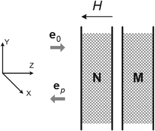
The relation between the falling and reflected
fields is established by the ratio
(14)
(14)
where N is the operator of ‘transmission’ of the ferrite layer when the field wave moves from left to right, Nrev is when the wave moves from right to left. In the expression (14)
,
vectors are written in the same XOY coordinate system, right-sided to the wave
. We do not account for reflections from the ferrite layer boundary, because in practice, the choice of geometry of the volume occupied by ferrite allows to reduce the reverse reflection from the boundary to almost zero. Details for polarization of radiation reflected from the front boundary, as well as change of ellipticity of radiation that passed through the layer and reflected backwards, are provided in [Citation14].
Analysis of the rotation of the centimeter-wave polarization plane in longitudinally magnetized ferrite washer was carried out in [Citation16], and the most detailed description of the electrodynamics of magnetized ferrite is provided in monographs [Citation14,Citation17,Citation18].
The most remarkable quality of a magnetized ferrite, due to its non-reciprocity, is that the reverse passage of the wave has its polarization plane rotated in the same direction and the same angle as at the direct passage. For non-zero magnetic field density, the operator N of the electromagnetic wave transformation in Cartesian polarization basis has the form
(15)
(15)
and the ferrite layer rotates the polarization plane of the passing wave at an angle α, without changing its elliptic parameters.
Angle is a function of magnetic field density H. For small H values, when the magnetization of the ferrite is far from saturation, and especially when
the field corresponding to the longitudinal ferromagnetic resonance values
is proportional to the value M (technical magnetization of ferrite) and the thickness of the ferrite layer d
(16)
(16)
The angle sign depends on the magnetic field polarity.
Waves of right and left circular polarization pass through ferrite with different phase delays. Since the energy absorption for orthogonal circular polarization waves in ferrite is the same, the operator in the expression (14) is identical to the operator
, and expression (14) takes the form (17)
(17)
(17)
Note that if you replace (in the geometry of Figure ) the ferrite layer with a mutual medium whose ‘passing’ properties are described by the P operator, the expression (17) looks like
This follows from the theory of linear interconnected quadpoles, and the backscattering operator of such model
is always symmetrical. For a magnetized ferrite, the backscattering operator is always asymmetrical
(18)
(18)
and at some value
, for which
has the form of an anti-symmetric operator
(19)
(19)
Due to the noted invariance of the anti-symmetric operator (see expression 12) regarding any transformations of the polarization basis (in monostatic case), the studied planar medium at
have unique properties for electromagnetic waves backscattering: all types of polarization of the incident wave are zero for this medium.
In order to verify this statement, an experiment was carried out using an experimental setup, the diagram of which is shown in Figure .
Figure 2. Diagram of the experimental setup.
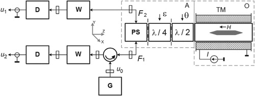
The experimental installation included a ferrite rod placed in a section of a round waveguide, shortened on one side. Solenoid electromagnet TM, on the axis of which the ferrite section was located, allowed to change the degree of the ferrite rod magnetization over a wide range by changing current in solenoid. The two sections of the round waveguide containing the phase non-absorbing plates
and
are connected to each other with the section containing ferrite rod on the one hand, and also with a round flange of the polarization splitter PS on the other side by means of rotating throttle joints. This allowed for quick changes of the phase plates
and
orientation, rotating the section around the axis by angle
for the plate
, and angle
for the plate
. The polarization splitter PS decomposes the input from the round wave flange into two orthogonal, linear-polarized components. W valves are used to match the detection heads D with outputs
and
of the polarization splitter PS.
The measurements were carried out as follows. High frequency 9.5 GHz signal from the generator G (G4-83) output was fed, via the circulator, to the polarization splitter PS input
. With that, a linearly polarized wave is excited at the output of section
inside the round waveguide. The wave's polarization plane is oriented along the OX axis of the XOY coordinate system (see Figure ), formed by orthogonal axes of the polarization splitter PS shoulders. The wave passes through all sections, gets reflected from the shorted end of the last section, and then passes through all sections in the opposite direction. At the PS splitter outputs
and
, the signals
,
are formed according to the ratio:
(20)
(20)
where
is the reflection operator for the section with ferrite, described by the expression (18);
is the transmission operator for the
plate;
is the transmission operator for the
plate. The signals
,
were received by linear detector heads whose output responses were evaluated for different angular positions of phase plates.
As can be seen from Figure , part (A) of the experimental assembly (dashed line) corresponds to the reciprocal antenna of a monostatic radar, the polarization properties of which may vary arbitrarily by specifying the phase plates orientation angles ,
. Part (O) of the assembly corresponds to the studied reflector.
Proceeding from the expressions (18), (19), we can figure that for some value of the current , flowing through the winding of the electromagnet TM, the operator S in the expression (20) must be anti-symmetric, and signals
,
must satisfy the ratio
(21)
(21)
Since the phase plates have eigen orthogonal polarizations and insert negligible losses in the energy of the transitioning waves, the next expressions are valid
(
– Hermitian conjugation sign), and therefore, we have
(22)
(22)
But for any nondegenerate we have the relation
(23)
(23)
and regardless of the angles
of the phase plates orientation in sections
,
, the expression (21) has the form
(24)
(24)
It follows that the amplitude of the signal for a certain magnetic field strength
must always be constant and equal to signal amplitude
of the generator G. At the same time, the amplitude of the signal
must always be zero. For signals
,
amplitude dependences were calculated with different magnetic field intensities (i.e. for different
in (18)) and different values of phase plates orientation angles
:
(25)
(25)
(26)
(26)
Operators of phase plates in Cartesian polarization basis in XOY coordinate system, combined with the axes of polarization splitter PS shoulders, have the form
(27)
(27)
(28)
(28)
Figure shows the calculated dependences of signals ,
amplitudes with different magnetization field values (curve numbers). From the expressions (25), (26) follows that the signals
,
amplitude does not depend on the
− plate orientation angle, and is determined only by two values:
and
.
Figure 3. Calculated dependences of signals u1/u1max (a) and u2/u2max (b) amplitudes with different magnetization field values.
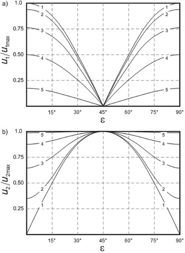
When , the signal
is zero for all possible values of the
– plate orientation angle
. At the same time the signal
in the orthogonal receiving channel is maximum and also does not depend on the
angle.
Experimental dependences of signals ,
amplitudes are presented in Figure . As you can see, the character of curves behavior is almost identical to Figure .
Figure 4. Experimental dependences of signals u1/u1max (a) and u2/u2max (b) amplitudes.
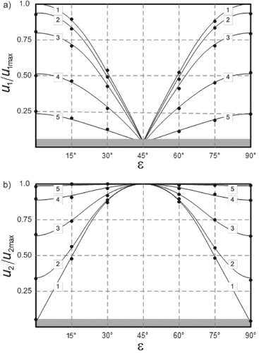
The most noticeable difference at the point of signal suppression (gray area) is explained by the imperfect coordination of the waveguide sections impedances and parasitic reflections from the phase plates and ferrite rod ribs. With a further increase in the magnetic field strength (an increase in the solenoid current
), the curves begin to repeat.
At the same time, the uncompensated surplus of the signal (by amplitude) is, as shown in Figure , less than minus 20 db to its maximum level, which is observed when
and
. When changing the
-plate angle, the
and
values underwent a small modulation, not exceeding 8% of the absolute values at each curve point. Parasite modulation of signals that arises during the
-plate rotation is also explained by the imperfect matching of individual units impedances in the experimental assembly. Comparison of the calculated and experimental data allows us to speak about the existence of an absolutely non-reciprocal reflector. One of the possible designs of such a reflector is determined by part (O) of the Figure experimental assembly at the magnetic field intensity
, when the angle
in the expression (21) is 45°.
3. Conclusion
The results of the work's previous section concerning the synthesis of the absolutely non-reciprocal reflector design allow to specify the method for the controlled radar reflector realization. This reflector allows to simulate the properties of backscattering for any medium [Citation20]. The obvious design solution for the simulator of an arbitrary scatterer is derived from the analysis of the expression (7): the field of an EM wave, scattered back by an arbitrary scatterer, is equivalent to the sum of the fields reflected by the reciprocal and absolutely non-reciprocal reflectors. The use of reflectors spaced by an angle not exceeding the angular resolution of the sounding radar while not exceeding the radar resolution in range allows to simulate an arbitrary scattering medium. At the same time, the control of the reciprocal and absolutely non-reciprocal parts of the simulator effective scattering area is carried out independently by adjusting the parameters of the reciprocal scatterer and the RCS of the absolutely non-reciprocal reflector.
Introduction of the MSM objects estimation methods into the algorithms of monostatic radar operation will allow to receive an additional channel of information for monostatic sounding of surrounding space.
Acknowledgements
We thank Malyutin N.D., Rovkin M.E. for assistance in discussing the results and Malyutin G.A. in preparing the manuscript.
Disclosure statement
No potential conflict of interest was reported by the author(s).
Additional information
Funding
Notes on contributors
Valeriy A. Khlusov
Valery Khlusov received his Doctor of Science degree in 2004 from Tomsk State University of Control Systems and Radioelectronics, Russia. His areas of research are theory and methods of processing vector signals in polarizing radar systems, polarization effects of radio wave propagation and their practical application, the use of complex signals in ranging problems.
Peter V. Vorob'ov
Peter Vorobyov had a PhD in physics and mathematics, until 2004, he worked as a research associate at the G.I. Budker Institute of nuclear physics, Siberian branch of the Russian Academy of Sciences.
References
- Bu Z, Wang Y, Liu J, et al. Comparison and analysis of Aerosol Lidar Network in Mega City of Beijing Using Real Lidar. 2019 International Conference on Meteorology Observations (ICMO); 2019 Dec 28–31. doi:10.1109/ICMO49322.2019.9026098.
- Burkatovskaya YB, Belov VV, Shamanaeva LG, et al. Monte Carlo method in acoustic sounding of the atmosphere. 2015 International Conference on Mechanical Engineering, Automation and Control Systems (MEACS); 2015 Dec 1–4. doi:10.1109/MEACS.2015.7414882.
- David G. Polarization-resolved backscattering from nanoparticles in the atmosphere: field and laboratory experiments. Claude Bernard Lyon 1 University, Physics and Astrophysics Doctoral School. Thesis of Degree of Doctor of Philosophy; 2013.
- Bian M, Dong X, Guo A, et al. Design and implementation of spaceborne Terahertz cloud radar. 2016 46th European Microwave Conference (EuMC); 2016 Oct 4–6. doi:10.1109/EuMC.2016.7824640.
- Vnotchenko SL, Dostovalov MY, Dyakov AV, et al. Aviation four-band radar complex “COMPACT” – features, results and development prospects // proceedings of the XXVIII Russian symposium “radar investigations of natural environments”. St Petersburg. 2013;1:34–44.
- Vnotchenko SL, Moussiniants TG, Ermakov RV, et al. Modern tendencies in the development of airborne synthesized aperture radars for remote sensing of the earth. 2018 XIV International Scientific-Technical Conference on Actual Problems of Electronics Instrument Engineering (APEIE); 2018. p. 439–443. doi:10.1109/APEIE.2018.8545651.
- Cantalloube HMJ. Real-time airborne SAR imaging. Motion compensation and Autofocus issues / Office National d’Etudes et Recherches Aero spaatiales, France, EUSAR; 2012. p. 734.
- Kuznetsov GY, Miloserdov MS, Temchenko VS, et al. Antenna beam broadening optimization in space-borne SAR with AESA. International Conference on Radar Systems (Radar 2017); 2017 Oct 23–26. doi:10.1049/cp.2017.0489.
- Boerner W-M, Yamaguchi Y. A state-of-the-art review in radar polarimetry and its applications in remote sensing. IEEE Aerosp Electron Syst Mag. 1990;5(6):3–6. doi:10.1109/62.54634.
- Vorob'ev PV, Kolokolov LV, Fogel VF. Ferromagnetic detector of (pseudo) Holston bosons. Part World. 1990;1(6):163.
- Kossel M, Benedickter HR, Peter R, et al. Microwave backscatter modulation systems. Conference Paper in IEEE MTT-S International Microwave Symposium Digest. IEEE MTT-S International Microwave Symposium; 2000 Feb. doi:10.1109/MWSYM.2000.862242.
- Kanareykin DB, Pavlov NF, Potekhin VA. The polarization of radar signals, Sovyet Radio (in Russian), Moscow (1966). (English Translation of Chapters 10–12: Radar Polarization Effects. CCM Int. Corp., G. Collier and McMillan, New York, NY. 10023).
- Bogorodsky VV, Kanareykin DB, Kozlov AE. Polarization of the scattered radio radiation of the earth covers. Gidrometeoizdat, Leningrad (in Russian); 1981; p. 279.
- Gurevich AG. Magnetic resonance in Ferrites and antiferromagnets. Moscow: “Nauka”; 1973; (in Russian).
- Khlusov VA. Parameterization of non-mutual media backscattering matrix of nonreciprocal media. Atmospheric Ocean Opt. 1995;8(10):1441 ( in Russian).
- Polivanov KM, Collie YN, Izv KMB. USSR Academy of Sciences, Ser. Fiz., XYIII (1954) 350 (in Russian).
- A.G. Gurevich. Ferrites at microwave frequencies. In Tybulewicz A., editor. Authorized translation from the Russian. London: Heywood and Co., Ltd; 1963. p. viii + 332. 140 s.
- Sul G, Uoker L. Issues of the waveguide propagation of electromagnetic waves in gyrotropic media. Moscow: Inostr. Lit. Publ.; 1955. p. 189 (in Russian).
- Khlusov VA. Transformation of the polarization basis in the radar channel. TU GA; Moscow, 1995. Methods and means of remote sensing: Collection scientific works of MSTU GA; Moscow, 1995.
- Osipov MV, Khlusov VA. Radar Reflector. RU 2398318 C1, H01Q 19/17.