
 ?Mathematical formulae have been encoded as MathML and are displayed in this HTML version using MathJax in order to improve their display. Uncheck the box to turn MathJax off. This feature requires Javascript. Click on a formula to zoom.
ABSTRACT
This paper describes a new design strategy which is used to obtain a fivefold increase in the 3 dB axial ratio bandwidth of linear to circular polarization convertors based on anisotropic frequency selective surfaces composed of single screens of cross slots. The performance improvement is obtained by employing stratified dielectric media to carefully tailor the shape of the TE and TM spectral transmission responses. We demonstrate that a bandwidth of 24.5% can be achieved at a center operating frequency of 10.6 GHz using an array of unequal length cross-slots embedded centrally between two 2.25 mm thick dielectric slabs (εr = 9.0). Moreover it is shown that the inherent self-filtering behavior of the structure provides greater rejection of unwanted signals than designs embedded in lower permittivity material. Computed and experimental axial ratio results are compared to verify the new design methodology.
Introduction
For providing high quality and reliable wireless links, many satellite and terrestrial point to point communications systems use circular polarization (CP) signals in preference to linear polarization (LP) wave propagation [Citation1]. This removes the need to carefully orientate the electric field vector of the transmit and receive antennas and mitigates the effects of multipath scattering and the Faraday effect which can change the plane of orientation of LP waves. CP waveforms are more difficult to generate because to achieve high polarization purity, the vertical and horizontal wave components must meet precise amplitude and phase criteria [Citation1]. The integration of a LP polarized source and a standalone transmission mode polarization convertor is an attractive option for generating CP waves. This enables design optimization of the antenna to be carried out more simply as a single entity, and moreover by the placing the convertor close to the radiating aperture combined polarization conversion, bandpass filtering [Citation2] and polarization agility [Citation3] are achievable. Several different transmission mode polarization convertor topologies have been reported in the literature [Citation4–16]. These arrangements are created by printing an array of continuous zigzag metal strips or weakly resonant discrete conductive elements on the surface of a single or closely spaced multiple dielectric sheets. Many of these structures exhibit low transmission loss outside the 3 dB axial ratio (AR) bandwidth (BW) and therefore are unable to provide high rejection of spurious signals. An alternative solution is to deploy strongly resonant anisotropic frequency selective surfaces (FSS) which are composed of asymmetrically shaped slot elements [Citation17]. This is potentially a better option for applications where the bandwidth requirement is less stringent, and it is desirable to provide additional functionality such as self-filtering capability [Citation2]. However, the drawback of these designs is that the axial ratio (AR) bandwidth (BW) is narrow and the insertion loss is about 3 dB. The latter intrinsic performance limitation can largely be mitigated by cascading two or more identical screens, but this has minimal effect on the bandwidth [Citation17]. The first published study of a single freestanding screen perforated with unequal length cross slots reported a 3 dB AR BW of 2.4% [Citation17], but more recently the authors have shown that this can be increased to 5.0% by optimizing the physical layout of the unit cells, [Citation18]. In [Citation19] a bandwidth of 7.9% was obtained from an arrangement which employed Polytetrafluoroethylene (PTFE) dielectric layers (εr = 2.1) to reduce the roll-off rate of the amplitude response plots above and below the resonant frequency in the TM and TE plane respectively. The purpose of this paper is to present an innovative design strategy which achieves a much wider bandwidth by placing the freestanding slot FSS symmetrically between two identical dielectric slabs with a much higher permittivity (εr=9.0) than reported in [Citation19]. It is shown that this creates an electromagnetic environment which produces much more advantageous shaping of the TE and TM transmission responses than previously observed. The additional design flexibility afforded by the wave behavior is exploited to achieve a fivefold increase (24.5%) in the 3 dB AR BW compared to the freestanding slot LP to CP transformer reported in [Citation18].
The structure of the paper is as follows: Section 2 provides an explanation of the principle of operation of the polarization convertor; in Section 3 the design of the FSS is discussed and simulated performance is presented and discussed. Manufacturing and measurement of the prototype is presented in Section 4 and concluding remarks are included in Section 5.
Principle of operation
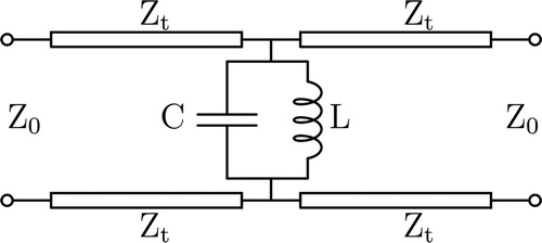
A slant 45° wave impinging on a screen with a unit cell similar to that shown in Figure (a) can be decomposed into electric vectors with equal amplitude and phase in the vertical (TE) and horizontal (TM) directions. On exiting the periodic structure, pure CP waves are transmitted when a phase difference of 90˚ is created between the two orthogonally orientated equal amplitude waves. At resonance an FSS composed of metal slots of length ∼λ/2 is matched to free space (377 Ω) and the signal transmits with very low attenuation. Incident energy of frequency slightly above or below resonance experiences either a capacitive or inductive environment and hence undergoes a phase advance/delay upon transmission from the structure. It is this feature that is used in polarization conversion. The criteria for CP generation is met by adjusting the lengths of the two orthogonal slots in each unit cell, so that one component of the incident wave is exposed to a capacitive and the other to an inductive reactance (longer and shorter slots respectively). In one case this produces a 45˚ phase advance and for the other wave orientation a 45° delay occurs at the crossover frequency where the transmitted power is equal and 3 dB below the value at resonance for the TE and TM waves. The frequency range over which the AR is below 3 dB is then obtained by adjusting the geometry and physical dimensions of the unit cell parameters [Citation17]. Encasing the screen between identical dielectric slabs creates an additional design parameter with which to further increase 3 dB AR BW, provided the unit cell dimensions have been adjusted to account for its presence [Citation19]. The thickness of these slabs are dependent on the operating frequency and the permittivity of the dielectric. Figure (b) shows the unit cell arrangement with the thin FSS embedded between two dielectric slabs of thickness (t). Useful insight into the principle of operation can be obtained from the equivalent circuit model of the structure depicted in Figure . The FSS is modeled as a parallel LC resonant circuit connected to a 377/ (Zt) Ohm transmission line of length “t” at the input and output ports of the circuit. The values of L and C for the vertical and horizontally orientated coupled slots can be obtained using full wave EM simulations in conjunction with the Nelder-Mead method for curve fitting as described by the authors in [Citation20].
Figure 1. Unit cell configuration of (a) a freestanding FSS and (b) FSS embedded between dielectric.
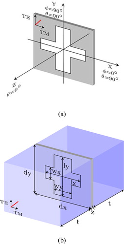
Figure 2. Equivalent circuit model for the dielectric clad resonant aperture FSS Polarization convertor.
Design and simulated performance
CST Microwave Studio was employed to optimize the design and obtain the physical dimensions of the unit cells and the thickness of the dielectric slab for each of the structures (Table ) that were investigated. The Metamaterial Unit-cell Design Environment template was used, with a normal background selected. The ports were moved away by 14 mm distance from the perforated array to ensure higher order modes dissipated before reaching the surface, while unit-cell boundaries were selected along the x and y directions to model an infinite periodic structure. The frequency domain solver was selected to simulate the unit cell at normal and oblique angles of incidence. The FSS screens were modeled with the slots formed on the surface of a 140 µm thick metalized Polyethylene terephthalate (PET) sheet (εr = 2.95, tanδ=0.025), to replicate the material that was used to construct the prototype array reported in [Citation19], and in this study. The perforated sheets are placed in the center of dielectric slabs with relative permittivity of 2.1, 4.5 and 9.0, and in the numerical model the thickness (t) was adjusted for each arrangement as given in Table . Each structure was engineered to work at normal incidence at a center frequency of ∼10.3 GHz. The objective of the design strategy was to reduce the amplitude roll-off rate below the resonant frequency (maximum transmission) of the shorter horizontal (TE) slots and above the resonant frequency for the longer vertical (TM) slots. The maximum 3 dB AR BW is achieved because the amplitude difference and variation from phase quadrature is minimized above and below the center working frequency corresponding to the TE and TM amplitude crossover point where the minimum AR occurs. The spectral transmission amplitude and phase and axial ratio plots are illustrated in Figure where it is shown that the LP to CP convertor modeled with εr=2.1 (PTFE), gives a 3 dB AR BW of 7.9% [Citation19]. In contrast to the monotonic curves exhibited by this structure around the cross-over point, slot FSS embedded in higher permittivity material exhibit more complex amplitude responses, because of the combined effect of the different impedances presented by the periodic array and the dielectric slab. The individual resonances that are generated by the slot array and dielectric slabs are used in our designs to independently optimize the shape of the transmission response plots in the TE and TM planes. The computed spectral transmission for the FSS symmetrically embedded in a substrate with εr = 4.5 shows that an anti-resonance is generated in the TM plane at 7.6 GHz. In conjunction with this, a secondary peak which is excited at ∼9.9 GHz, is used to reduce the amplitude difference between the TE and TM waves below the center working frequency of this polarization convertor. By careful design of the physical dimensions of the slots and thickness of the dielectric layers, a further and much more significant performance improvement is obtained for the arrangement modeled using a slab with a dielectric constant of 9.0. For this structure a stronger anti-resonance occurs at 7.2 GHz and a more prominent secondary peak is generated in the TM plane at 10.9 GHz where the encasing dielectric slabs (total thickness ∼λ/2) presents a good impedance match to free space. This feature exists independently of the slot array [Citation21] which was designed to resonate at 4.3 GHz. The behavior of the transmitted TE waves is more complex than the other two cases studied, because as illustrated in Figure (a), in our design the spectral response was tailored to produce a secondary peak and null at 10.7 and 11.5 GHz respectively. Because the peak to null variation is very small, the TE amplitude response above the center design frequency (10.6 GHz) is significantly flattened. Moreover, it is observed that there are two intersection points at 10.3 and 11.4 GHz (as shown by A and B respectively in Figure (a)), where the amplitude of the TE and TM waves are identical and the phase difference is about 90˚ in both cases. The axial ratio plots depicted in Figure (c) show that this means of shaping the spectral transmission curves produces AR nulls at the two crossover frequencies, which results in a further significant increase in the 3 dB AR BW from 12.3% (εr = 4.5) to 24.5% (εr = 9.0). It is evident that the bandwidth enlargement is more significant above the design frequency and can be attributed to the formation of the AR minimum at the second intersection point. The results depicted in Figure (a) show that better self-filtering is obtained in the 3–13 GHz frequency range compared to the two other dielectric clad structures studied, and for this polarizer design, more than 10 dB signal rejection is achieved above 13 GHz (TE and TM) and below 3 and 8 GHz for TM and TE waves respectively. Moreover the signal rejection obtained is significantly higher than single layer printed LP to CP polarizers based on zigzag patterns [Citation11,Citation12] and discrete FSS elements [Citation4–6]. Figure presents the computed S21 and S11 amplitude responses for this high permittivity structure (εr = 9.0) over the frequency range 9–12 GHz, for the TE and TM wave components. The inherent self-filtering of the polarization convertor is demonstrated above and below the working frequency range (9.3–11.3 GHz), defined by the 3 dB AR bandwidth. For example, at 9 GHz the reflection coefficients are much larger than the transmission coefficients with values obtained from the computer model of −1.2/−1.7 dB (TE/TM) and −6.1/−5.0 dB (TE/TM) respectively. The TE/TM wave responses are of equal amplitude (−3 dB) at 10.4 and 11.3 GHz, and between these two frequencies, the transmission loss is slightly lower.
Figure 3. Computed (a) amplitude, (b) phase and (c) axial ratio responses for arrangements with dielectric material of εr = 2.1, 4.5, 9.0.
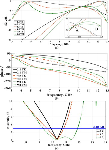
Figure 4. Computed S21 and S11 amplitude responses for the FSS based LP to CP convertor clad with dielectric material of εr = 9.0.
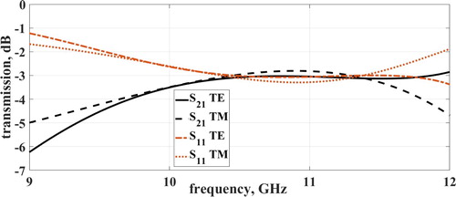
Table 1. Dimensions of FSS unit cells (mm).
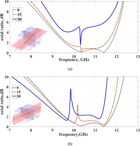
Although these structures are normally deployed at normal incidence in antenna systems [Citation2, Citation3], oblique incidence performance along two cardinal planes () was also simulated for the high permittivity structure. Figure (a) shows the axial ratio responses along the
plane (XZ plane in Figure (a)), where the 3 dB AR BW decreases slightly from 24.5% at normal incidence to 21.8% at
while maintaining a center operating frequency of 10.6 GHz. However the performance degrades significantly at
and the AR is higher than 3 dB except for a narrow band of about 0.5% which is centered at 10.3 GHz. Figure (b) shows the computed axial ratio responses for angles of incidence scanning along the
plane (YZ plane in Figure (a)). As the angle of incidence is increased beyond 0°, the axial ratio plots exhibit good frequency stability but the structure exhibits dual-band operation. At
incidence the lower 3 dB AR BW is 9.2% centered frequency of 9.7 GHz, and for the upper channel the bandwidth is 14.1% centered at 11 GHz. At 30°, the lower bandwidth reduces to 7.2% and the center frequency shifts downwards 9.4 GHz. The computed upper bandwidth is 9.3% centered at 10.9 GHz. The observed degradation in the polarization purity of the transmitted waves increases the minimum AR to 1.3 and 1.6 dB for the lower and upper bands respectively.
Figure 5. Computed axial ratio responses for high permittivity FSS LP to CP convertor (εr=9.0) at oblique angles of incidence from scanning along orthogonal planes
(a) and
(b).
In summary, the higher permittivity structure investigated in this study exhibits a much better LP to CP wave conversion performance than the PTFE (εr=2.1) embedded structure reported in [Citation22], when exposed to waves incident up to at least 15° in both cardinal planes.
Fabrication and experimental results
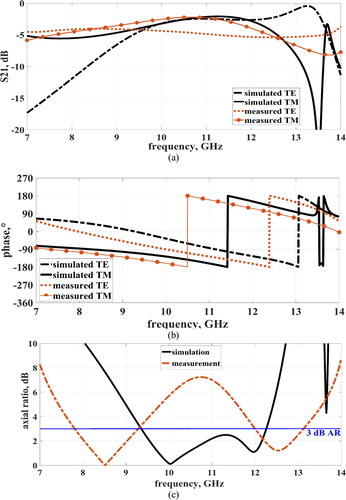
To verify the design methodology, a LP to CP polarization converter was designed using Taconic RF-10 (εr = 10.2 +/- 0.3), loss tangent = 0.0025 substrate. The structure used available material in the laboratory, and was constructed with 6 layers of the substrate with an average thickness of 0.25 mm and 4 layers with an average thickness of 0.64 mm. The copper cladding was stripped from each of the sheets prior to bonding, with the exception of one of the thicker substrates. On this layer, the copper was removed from one side and the FSS patterned sheet was etched on the opposite surface as shown in Figure (a). The individual layers were bonded together using Taconic TacBond ht 1.5 bonding film in a platen press at a pressure of 10 Bar and temperature of 220°C, while the complete structure was held in a vacuum throughout the bonding process. The total time for the bonding process (inclusive of the cooling cycle) was 45 min. Figure (b) illustrates a side view of the bonded structure. As the electrical properties and thickness of the available material differ slightly from the values shown in Table for (εr = 9.0, loss tangent = 0), the dimensions of the patterned array and structure were adjusted to give a simulated amplitude and phase response and 3 dB AR BW of 27% as depicted in Figure (a,b,c) respectively.
Figure 6. Image of the manufactured FSS before embedding process (a) and a side view illustration of the complete embedded structure where X represents a 0.25 mm thick dielectric sheet and Y represents a 0.64 mm sheet (b).
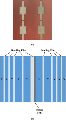
Figure 7. Measured and computed (a) amplitude, (b) phase and (c) axial ratio responses for the manufactured LP to CP polarization convertor.
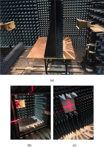
TE and TM wave transmission measurements were made in an anechoic environment using an Agilent PNA 8631A which was connected to two standard gain horns separated by a distance of 140 cm. Between these horns, the device was inserted in the center of a 91 × 91 cm screen covered with radar absorbent material and carefully aligned with the dielectric clad FSS. The transmit horn was adjusted to illuminate the FSS with a slant 45° signal and the receive antenna was mounted onto an NSI 2000 planar nearfield scanner which allowed for automated alignment and rotation of the horn from 0° to 90° in order to record the amplitude and phase of the TE and TM waves. Figure (a,b,c) illustrates the experimental arrangement.
Figure 8 Photograph of the test environment (a), the mounting frame (b) and arrangement with manufactured FSS in place (c).
As shown in Figure (a), a secondary resonance in the TM response is measured at 10.6 GHz, with the TE response plot intersecting at 8.5 and 12.5 GHz. This produces the two axial ratio nulls shown in Figure (c) and demonstrates that the shape of the measured AR response is broadly similar to the results obtained from the numerical simulations. The differences can largely be attributed to the measured TE spectral response, which is particularly sensitive to variations in the material permittivity and the set-up alignment. In addition, the requirement to simultaneously bond all 10 substrate layers to create the 4.4 mm thick structure introduces dimensional and permittivity uncertainties. This has a major impact on the frequency of the two TE/TM amplitude crossover points, which in our case are shown to be separated further apart than the crossovers predicted at 10.0 and 12.0 GHz, giving a measured dual-band performance of 17.3% centered at 8.5 GHz and 9.0% at a center frequency of 12.5 GHz. Table presents a comparision of the measured and simulated responses for the manufactured structure.
Table 2. Comparison of simulated and measured results for the manufactured structure.
Conclusions
The feasibility of employing material with a permittivity in the range of 2.1–9.0 to increase the 3 dB AR BW obtained from a LP to CP polarization converter based on a cross slot FSS has been investigated. Numerical predictions underpinned by experimental results show that the supporting dielectric layer can be used to shape the TE and TM transmission responses in order to satisfy the criteria for CP signal generation over a large frequency range. Our results demonstrate that a fivefold increase in bandwidth is achieved when the freestanding array is symmetrically embedded between two 2.25 mm thick slabs with a relative permittivity of 9.0. In conjunction with this, the self –filtering properties of the structure can be used to reject out of band signals and hence reduce the noise floor when it is integrated with a horn antenna [Citation2]. The improved design can be used as a building block to construct a robust multilayer FSS based polarization convertors which could potentially be engineered to exhibit much lower loss [Citation17] and a further increase in bandwidth. Table provides a comparison of the results obtained for the optimum design reported in this paper, with the performance reported in the open literature for single layer transmission mode FSS based LP to CP polarization convertors.
Table 3. Comparison of optimum FSS LP to CP converter design presented in this paper, with previous published work for transmission mode single layer structures designed for normal incidence operation.
Acknowledgements
The first author is supported by a PhD scholarship funded by the Department for the Economy (DfE) Northern Ireland. The authors would also like to thank Mr. Hong Ma, Mr. Georg Grainger and Dr. Sandeep Kumar for their assistance in manufacturing the structure.
Disclosure statement
No potential conflict of interest was reported by the author(s).
Additional information
Funding
Notes on contributors
Sarah Clendinning
S. Clendinning received her MSci degree in Physics from Queen’s University Belfast in 2017. She is currently a PhD student in electronic engineering at the Center for Wireless Innovation (CWI) at Queen’s University Belfast. Her research interests include polarization conversion using resonant frequency selective surfaces.
R. Cahill
R. Cahill received a BSc degree in Physics from the University of Aston in Birmingham 1979 and a PhD degree in microwave electronics from the University of Kent 1982. He is currently a reader in microwave engineering at Queen’s University Belfast in the UK. His research interests include the development of space qualified Frequency Selective Surfaces (FSS), ultra-thin resistively loaded FSS based microwave absorbers, linear to circular FSS based polarizers, and electronically controlled liquid crystal antennas. He has authored over 210 publications and holds 5 global patents.
D. Zelenchuk
D. Zelenchuk, PhD, Senior Member of the IEEE, is a Lecturer with the Centre for Wireless Innovations, ECIT, Queen's University Belfast, UK. His research interests include antennas and frequency selective surfaces, mobile, automotive and space applications, electromagnetic field theory, material characterization, millimeter-wave circuits, and advanced packaging, propagation in complex environments, and various physical phenomena. He has authored over a 100 publications.
V. Fusco
V. Fusco FREng, FIEEE, FIET, FIAE, MRIA. In 2012 he was awarded the IET senior achievement award, the Mountbatten Medal for seminal contributions in the field of microwave electronics. His fundamental work on active antenna front-end techniques and artificial electromagnetic materials has provided generic advances in low cost phased and self-tracking antenna array architectures. He has written over 550 papers and two books and holds 12 antenna related patents. He co-founded a major research Electronics, Communications and Information technology Research Institute at Queens University Belfast which now employs over 200 people.
References
- Toh B, Cahill R, Fusco V. Understanding and measuring circular polarization. IEEE Trans. Educ. 2003;46(3):313–319.
- Barbuto M, Trotta F, Bilotti F, et al. A combined bandpass filter and polarization transformer for horn antennas. IEEE Antennas and Wirel Propag. Lett. 2013;12:1065–1068.
- Farzami F, Khaledian S, Smida B, et al. Reconfigurable linear/circular polarization rectangular waveguide filtenna. IEEE Trans. on Antennas and Propag. 2018;66(1):9–17.
- Naseri P, Matos S, Costa J, et al. Dual-band dual-linear-to-circular polarization convertor in transmission mode application to K/Ka-band satellite communications. IEEE Trans Antennas and Propag. 2018;66(12):7128–7137.
- Hosseini M, Hum S. A circuit driven design methodology for a circular polarizer based on modified Jerusalem cross grids. IEEE Antennas and Propag. 2017;65:5322–5331.
- Blanco D, Sauleau R. Broadband and broad-angle multilayer polarizer based on hybrid optimisation algorithm for low-cost Ka-band applications. IEEE Antennas and Propag. 2018;66(4):1874–1881.
- Lerner D. A wave polarization converter for circular polarization. IEEE Trans on Antennas and Propag. 1965;13(1):3–7.
- Baoqin L, Wu J, Da X, et al. A linear-to-circular polarization converter based on a second-order band-pass frequency selective surface. Appl Phys A. 2017;123(1):43.
- Mahdi F, Armaki S. Design of metasurface polarization converter for near-field application; stacked conical horn antenna for circular polarization. Int J of RF and Microw Computer-Aided Eng. 2019;29(7):21712.
- Peng F, Hu W, Guo W, et al. Design of a wideband planar linear-circular polarization converter with centrosymmetric dual-loop elements. Prog. In Electromagn Res. 2018;74:83–92.
- Baena J, Glybovski S, Risco J, et al. Broadband and thin linear to circular polarisers based on self-complementary zigzag metasurfaces. IEEE Antennas and Propag. 2017;65(8):4123–4133.
- Peng F, Shen Z, Wen X, et al. A single-layer circular polarizer based on hybrid meander line and loop configuration. IEEE Trans on Antennas and Propag. 2015;63(10):4609–4614.
- Xiaoliang M, Huang C, Pu M, et al. Single-layer circular polarizer using metamaterial and its application in antenna. Microw and Optical Technol Lett. 2012;54(7):1770–1774.
- Wang H, Cheng Y. Single-layer dual-band linear-to-circular polarization converter with wide axial ratio bandwidth and different polarization modes. IEEE Transactions on Antennas and Propag. 2019;67(6):4296–4301.
- Wu S, Zha D, He Y, et al. Design of stable and high-efficiency graphene-based polarizers for oblique angle of incidence in terahertz frequency. Appl. Opt. 2019;58:492–497.
- Ghosh S, Das S, Bhattacharyya S. Transmittive-type triple-band linear to circular polarization conversion in THz region using graphene-based metasurface. Opt Commun. 2021;480:126480.
- Euler M, Fusco VF, Cahill R, et al. Comparison of FSS based linear to circular polarization convertor geometries. IET Microw Antennas and Propag. 2010;4(11):1764–1772.
- Clendinning S, Cahill R, Zelenchuk D, et al. Bandwidth optimization of linear to circular polarization convertors based on slot FSS. Microw and Optical Technol Lett. 2019;61(5):1200–1207.
- Clendinning S, Cahill R, Zelenchuk D, et al. Dielectric embedded bandpass FSS linear to circular polarisation transformers. Proc. 13th European Conference Antennas and Propaga.; 2019 Mar 31-Apr 6; Krakow, Poland. 1-5.
- Clendinning S, Cahill R, Zelenchuk D, et al. Equivalent circuit model for linear to circular polarisation convertors based on bandpass FSS screens. Loughborough Antennas and Propag. Conf.; 2018 Nov 12-13; Loughborough;1-6.
- Callaghan P, Parker EA, Langley RJ. Influence of supporting dielectric layers on the transmission properties of frequency selective surfaces. IEEE Proc. Microw, Antennas and Propag. 1991;138(5):448–454.
- Clendinning S, Cahill R, Zelenchuk D, et al. Influence of dielectric layers on performance of transmission mode frequency selective surface based linear to circular polarization transformers. Microw. and Optical Technol. Lett. 2020; 62(4): 1815–1823.