
 ?Mathematical formulae have been encoded as MathML and are displayed in this HTML version using MathJax in order to improve their display. Uncheck the box to turn MathJax off. This feature requires Javascript. Click on a formula to zoom.
Abstract
When reinforced with conductive fibers, woven composites can exhibit interesting shielding properties. This paper focuses on their response for obliquely incident plane waves in the high-frequency range (500 MHz to 40 GHz). A two-step homogenization technique is carried out. First, the composite response (shielding effectiveness and reflection coefficient) is computed using a 3D finite element simulation, then the effective properties are estimated by implementing an optimization process to solve the inverse problem. Results show that composites effective properties are independent of the angle of incidence and wave configuration. This suggests that oblique incidence scenarios can be studied by homogenizing the material based on the case of normal incidence.
1. Introduction
Composites are engineered by combining two or more materials in order to form a new heterogeneous material having different, usually optimized, properties. Epoxy matrices reinforced with woven fibers are typically used for their lightweight and mechanical strength. When the fiber constituent is, partially or fully, electrically conductive, these materials become good candidates for shielding applications in the automotive and aerospace industries.
Braided fibers are partially conductive when strands running the length (or width) of the fabric are made from a bundle of, usually, graphene-based fibers [Citation1]. In this case, material conductivity is influenced by a number of factors (volume fraction of conductive fibers, frequency, temperature). A wide range of conductivities has been reported for these bundles. Studies in [Citation2–4] show that some carbon fibers exhibit electrical conductivities starting from a few S/m. Whereas other carbon-based fibers can be conductive up to 100 kS/m [Citation5,Citation6]. This flexibility in fiber design has a direct influence on the shielding properties of the manufactured composite. On the other hand, greater shielding effectiveness values can be obtained if metallic fibers are used [Citation7]. In this case, fully conductive fibers made from copper or steel provide the resulting composite with even higher levels of shielding.
Electromagnetic (EM) studies aimed at estimating the Shielding Effectiveness (SE) of woven fiber composites show that three main approaches can be adopted. Studies based on analytical formulas assimilate the woven composite to stacked panels of unidirectional fibers. This provides a workaround for the complex geometry and gives fast results by using mixing rules such as those proposed in [Citation8,Citation9]. Numerically based studies [Citation10,Citation11], while more time consuming, offer a more comprehensive solution as different numerical methods can be used over broad frequency bands and the woven fabric can be taken into account more accurately (elliptically shaped fibers, electrical contact between conducting fibers). Techniques combining analytical, numerical and/or experimental work can also provide estimations of composites EM response. For instance, in [Citation12] measured parameters are implemented into an analytical formula to calculate the transmission coefficient of stratified carbon fiber composites. Experimental investigations can also be conducted separately to obtain estimates of transmission coefficients. This is shown to be the case in [Citation13–15], where coaxial transmission lines and free space measurement systems are used to obtain shielding effectiveness estimates for composite samples.
Composite materials are used for shielding applications in structure form, i.e. complex shielding enclosures. These structures are typically modeled using numerical simulation methods. However, the heterogeneous nature of woven fiber composites at the microscopic level renders large-scale modeling difficult. Replacing the composite with an electrically equivalent medium through an appropriate homogenization method makes it possible to simulate the EM response of heterogeneous composite structures. Because of the limitations of classical mixing formulas [Citation16], in this paper, a numerical homogenization technique is proposed. In previous work [Citation17], the technique is carried out for a normally incident plane wave. However, in most realistic scenarios, the studied materials are subjected to waves with arbitrary angles of incidence and configurations. Thus, in this paper, the method is extended to take into consideration the case of an obliquely incident excitation (both perpendicular and parallel configurations are studied). This generalizes the technique by extending its application domain and allows for a comprehensive study regarding the effect of the incidence angle on the computed equivalent medium.
The paper is divided into two main parts. In the first section, the EM response of homogeneous plates is studied using an analytical formula and a 3D finite element simulation. This prepares the way for the second section in which the homogenization technique is introduced. The response of the composite is computed using the presented finite element simulation, then the inverse problem is solved for the effective properties of the material. Finally, a conclusion is drawn as to the relationship between the angle of incidence and the homogenized medium.
2. Reflection and transmission coefficients for a homogeneous isotropic material
In this first section, the case of an infinite, homogeneous and isotropic plate is considered. The transmission and reflection coefficients are given in analytical form then validated using Finite Element simulation. The methods presented here will then be used in the homogenization process for composites containing woven conductive fibers.
2.1. Analytical calculations
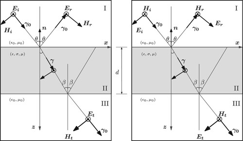
The general EM problem of transmission and reflection in a multilayered medium is studied in [Citation18,Citation19]. For the three-layer medium of Figure , these coefficients can be analytically calculated for both Transverse-Electric TE and Transverse-Magnetic TM cases of a linearly polarized incident plane wave. The reflection coefficient relates the amplitude of the incident wave
to that of the reflected wave
in region I. The transmission coefficient
is directly related to SE. It is defined as the ratio of the transmitted wave's amplitude
(region III) to the incident wave's amplitude
(region I). In dB, these coefficients are expressed as follows:
(1)
(1) where
and
ω is the angular frequency, θ and β are the incidence angles in regions I and II, respectively,
and γ are the propagation constants in regions (I, III) and II, respectively, d is the thickness of the plate represented by region II.
and
are the electrical properties in regions (I,III) and II, respectively, with ϵ the permittivity, σ the conductivity and μ the permeability. The symbol
refers to the configuration of the incident wave.
and
are the Fresnel reflection and transmission coefficients between regions.
Figure 1. Transmission and reflection of an obliquely incident plane wave in a three-layer medium. TE (left) and TM (right) configurations.
2.2. Finite element FE computations
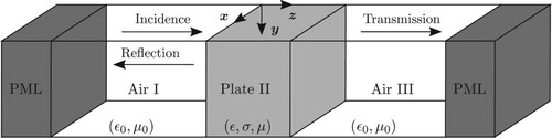
In this section, the validity of the presented analytical formula is verified using the Finite Element Method (FEM). The three-dimensional computational domain of Figure is studied with periodic boundary conditions and Perfectly Matched Layers PMLs which are fictitious layers added to absorb undesired reflected waves [Citation20]. The EM propagation equation is solved for the electric and magnetic fields using Comsol Multiphysics. The reflection and transmission coefficients are then computed.
Figure 2. Computational domain for finite element simulation.
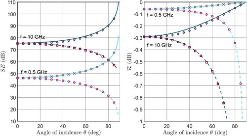
Multiple parametric studies are conducted for different isotropic plates, frequencies and angles of incidence. For the sake of clarity, only one material is presented here. It is a 1 mm thick, non-magnetic plate, having a relative permittivity of 10 and a conductivity of S/m. The SE and reflection coefficient
are computed for both TE and TM cases using FEM and the analytical formula. The results, represented in Figure , are a function of the angle of incidence θ for frequencies
GHz. The good agreement between the analytical and numerical results as well as the matching coefficients in the case of normal incidence (
) justify the validity of the calculation methods. The analytical form has the advantage of giving fast results. It will be used in the homogenization process for estimating the effective electrical properties. The FEM model will serve a double purpose: obtaining the transmission and reflection coefficients for a unit-cell of the woven composite and validating the homogenization process by simulating the response of the resulting equivalent medium.
Figure 3. Shielding Effectiveness SE (left) and reflection coefficient (right) of a homogeneous plate (
,
S/m,
, d = 1 mm) for TE and TM incident waves over different frequencies f: analytical – TE case (straight lines), analytical – TM case (dashed lines) and FEM (markers) results.
3. Homogenization of woven composites
3.1. Studied material and proposed technique
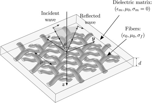
The studied material (Figure ) is a fiber-reinforced composite formed by combining a dielectric matrix and woven conductive fibers. These woven fibers can be made of conductive metals to which an epoxy resin is added according to a sheet molding compound manufacturing process [Citation7]. Otherwise, each strand of fiber is formed by grouping, on the microscopic scale, a number of individual fibers thus forming a bundle of fibers [Citation1]. In this paper, the material is studied on the mesoscopic scale. Each bundle of fibers is modeled as a single fiber having an electric conductivity that is equivalent to the conductivity of the group of fibers that constitutes it. This supposes that the material has already underwent a step of homogenization to get an estimate of the effective conductivity of its bundles of fibers. Reported estimations of this conductivity can vary from a few S/m to a few hundreds of kS/m [Citation2–6] depending on the used material, temperature, frequency and filling ratio within the bundle. Using the mesoscopic scale as a starting point, the proposed homogenization technique can be applied.
Figure 4. Woven fiber reinforced composite material.
The estimation of global effective properties (to go from mesoscopic to macroscopic scale) is done numerically according to a two-step process. The homogenization is based on the shielding effectiveness and reflection coefficient of the material. Thus, in the first step, these coefficients are computed numerically using FEM. The computational domain represented in Figure is maintained, the isotropic plate of region II is replaced by a periodic unit-cell of the woven composite. Floquet boundary conditions are applied to account for this periodicity. Thus, results obtained from this analysis take into account any scattering that can be introduced by braided fibers when illuminated by an incident plane wave. The obtained coefficients ( and
) for a certain material and wave configuration are then used in the second step for estimating the effective properties. The homogenization relies on the existence of a fictitious homogeneous medium (defined by its electrical permittivity
and conductivity
) having the same EM response as the composite. The equivalent properties, based on this assumption, are the solution to an optimization problem. The cost function
is a combination of the simulated coefficients of the composite (
,
) and those of the equivalent plate (
,
) evaluated using the analytical formula validated in the first section.
is written as
(2)
(2) This cost function is minimized using a genetic algorithm [Citation21]. This non-deterministic algorithm is well suited for nonlinear minimization problems where the presence of local minima is a possibility. Although the convergence of genetic algorithms is slower than deterministic methods around the global minimum, the computations that are done here exhibit a fast convergence (a few seconds). The first step consisting in finite element computations remains the most time consuming of the proposed method.
As evidenced by the results of the first section, for a conductive plate, the order of magnitude of the SE is much higher than that of the reflection coefficient. Two regularization coefficients are added to the optimization function to take into account this imbalance. For each configuration and angle of incidence, is multiplied by
and vice-versa. The validity of this model is tested in the next section.
3.2. Results for TE configuration
The presented homogenization technique is carried out for the woven fiber composite of Figure . Material dimensions and properties are given in Table . The composite is considered to be non-magnetic, the effective properties are reduced to one parameter: the effective conductivity . Figure shows the results of the homogenization process for multiple fiber conductivities and a frequency of 0.5 GHz as a function of the angle of incidence in the case of a TE excitation. First, the response of the composite is computed using FEM. Then, the effective conductivity is estimated by solving the optimization problem. Once the equivalent medium is obtained, its coefficients are numerically computed and compared to those of the heterogeneous material. The good agreement between the properties of the composite and those of the equivalent medium shows that the composite can be accurately homogenized using the proposed technique. Moreover, it can be shown that, for the considered frequency of 0.5 GHz, material thickness (in this case approximately equal to
) is smaller than (or has the same order of magnitude as) skin depth δ (for example:
for
S/m and
for
kS/m). This explains the non-negligible effect that angle of incidence has on the obtained shielding effectiveness and reflection coefficient.
Figure 5. Shielding Effectiveness (left) and reflection coefficient
(right) for the composite of Figure and Table (markers) and its equivalent medium (lines) computed using FEM. Case of a TE incident wave at f = 0.5 GHz for different fiber conductivities
and effective conductivities
.
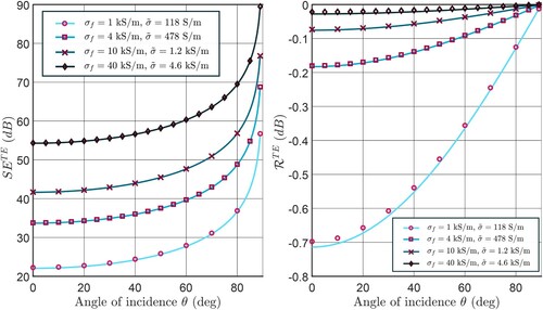
Table 1. Properties and dimensions of the woven composite sample.
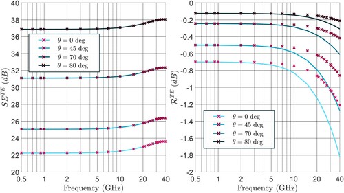
Figure depicts the homogenization results for the composite of Table having kS/m as a function of frequency for different angles of incidence. The results obtained for the reflection coefficient become less accurate when frequency increases. However, if the frequency range is restricted to the region below 10 GHz, the relative error for this composite remains below 20% whatever the incidence angle. On the other hand, examining the obtained shielding and reflection levels leads to the conclusion that absorption loss is dominant for the studied material. This is consistent with the conductive nature of the fibers. Stable shielding levels observed for the lower frequencies account for the resistive behavior of the composite. These levels exhibit a modest rise when frequency increases, which marks the effect of skin depth. Shielding levels then reach a maximum value and start to decrease (not shown here). At this point, the inductive effect created by the braided fibers becomes dominant.
Figure 6. Shielding effectiveness (left) and reflection coefficient
(right) for the composite of Figure and Table (markers) and its equivalent medium (lines) computed using FEM. Case of a TE incident wave for a fiber conductivity
kS/m, different angles of incidence and frequencies.
3.3. Results for TM configuration
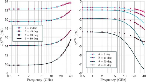
The same study is conducted in the case of a composite (Figure , Table ) illuminated by an obliquely incident, TM wave at f = 0.5 GHz. Results obtained from the homogenization process (Figure ) show a good correlation between the response of the composite plate and that of the equivalent medium computed by solving the optimization problem presented in the paper. The same observations can be made for the frequency study (Figure ). SE results are accurate up to 40 GHz, whereas reflection coefficient estimates deviate from FEM results as frequency increases.
Figure 7. Shielding effectiveness (left) and reflection coefficient
(right) for the composite of Figure and Table (markers) and its equivalent medium (lines) computed using FEM. Case of a TM incident wave at f = 0.5 GHz for different fiber conductivities
and effective conductivities
.
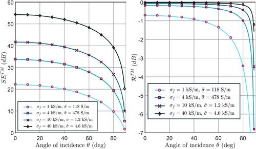
Figure 8. Shielding effectiveness (left) and reflection coefficient
(right) for the composite of Figure and Table (markers) and its equivalent medium (lines) computed using FEM. Case of a TM incident wave for a fiber conductivity
kS/m, different angles of incidence and frequencies.
In essence, the results that are shown in this section as well as the previous one demonstrate the proposed method's ability to estimate braided composites response over a wide range of frequencies. This is especially interesting in the dynamic range because finite element simulations provide, through solving Maxwell's equations, an accurate study of the underlying phenomena. Concretely, these simulations enable the estimation of displacement currents, allow for studying the presence, or absence, of electrical contact between fibers and provide an estimation of a frequency threshold above which the composite becomes mostly inductive and therefore gradually loses its shielding properties. In this regard, it is worth noting that the studied composite constitutes a three-dimensional current network. It can then be modeled using an equivalent electrical network in the quasi-static frequency range [Citation11]. Indeed, in this case, fiber conductivities are known and transfer of electrons from one fiber to another can be modeled supposing that there is direct contact between them. The main advantage of the proposed method resides then in its ability to account for the effect of high frequencies.
3.4. Discussion
The results that are shown in Figures and indicate that effective properties are independent of the configuration and angle of incidence of the EM wave. The computed effective conductivity is however a function of material properties, dimensions and frequency of EM excitation. This suggests that if the composite is homogenized for a normally incident plane wave, then its general response (shielding effectiveness and reflection coefficient for any angle of incidence) can be computed using a simple analytical formula based on the obtained effective property. The effective conductivity at normal incidence becomes an intrinsic characteristic of the material.
4. Conclusion
Composite materials can be used for shielding applications when reinforced with conductive fibers. In this paper, their effective electromagnetic properties are estimated for obliquely incident plane waves using a numerical homogenization technique. Simulation results suggest that, unlike the electromagnetic response of composite materials (shielding effectiveness and reflection coefficient), their effective properties are independent of the angle of incidence and wave configuration. An important inference of this observation is that realistic scenarios where a composite is subjected to an obliquely incident illumination can be accurately studied by homogenizing the material based on a normal incidence approach.
Disclosure statement
No potential conflict of interest was reported by the author(s).
Additional information
Funding
References
- Mirotznik MS, Yarlagadda S, McCauley R, et al. Broadband electromagnetic modeling of woven fabric composites. IEEE Trans Microw Theory Tech. 2012 Jan;60(1):158–169.
- Zhang M, Han C, Cao WQ, et al. A nano-micro engineering nanofiber for electromagnetic absorber, green shielding and sensor. Nano-Micro Lett. 2020 Nov;13(1):27.
- Wen B, Cao MS, Hou ZL, et al. Temperature dependent microwave attenuation behavior for carbon-nanotube/silica composites. Carbon. 2013 Dec;65:124–139.
- Cao MS, Song WL, Hou ZL, et al. The effects of temperature and frequency on the dielectric properties, electromagnetic interference shielding and microwave-absorption of short carbon fiber/silica composites. Carbon. 2010 Mar;48(3):788–796.
- Newcomb BA. Processing, structure, and properties of carbon fibers. Compos Part A: Appl Sci Manuf. 2016 Dec;91:262–282.
- Ebbesen TW, Lezec HJ, Hiura H, et al. Electrical conductivity of individual carbon nanotubes. Nature. 1996 Jul;382(6586):54–56.
- Al Achkar G, Pichon L, Bensetti M, et al. Homogenization of metal grid reinforced composites for near-field low frequency magnetic shielding. Prog Electromagn Res M. 2021;99:153–163.
- Holloway C, Sarto M, Johansson M. Analyzing carbon-fiber composite materials with equivalent-layer models. IEEE Trans Electromagn Comp. 2005 Nov;47(4):833–844.
- Sarto MS, Greco S, Tamburrano A. Shielding effectiveness of protective metallic wire meshes: EM modeling and validation. IEEE Trans Electromagn Comp. 2014 Jun;56(3):615–621.
- Li C, Lesselier D, Zhong Y. Scattering of obliquely incident electromagnetic plane waves by composite panel involving periodic arrays of circular fibers. IEEE Trans Antennas Propag. 2015;63(7):3168–3178.
- Senghor FD, Wasselynck G, Bui HK, et al. Electrical conductivity tensor modeling of stratified woven-fabric carbon fiber reinforced polymer composite materials. IEEE Trans Magn. 2017 Jun;53(6):1–4.
- Diaz Angulo LM, de Francisco PG, Gallardo BP, et al. Modeling and measuring the shielding effectiveness of carbon fiber composites. IEEE J Multiscale Multiphys Comput Tech. 2019;4:207–213.
- Lou CW, Chen AP, Lin CW, et al. Evaluation on manufacturing technique and electromagnetic shielding effectiveness of functional complex fabrics. J Electromagn Waves Appl. 2014;28(9):1031–1043. doi:https://doi.org/10.1080/09205071.2014.899167
- Gupta K, Abbas S, Abhyankar A. Ultra-lightweight hybrid woven fabric containing stainless steel/polyester composite yarn for total EMI shielding in frequency range 8–18 GHz. J Electromagn Waves Appl. 2015;29(11):1454–1472. doi:https://doi.org/10.1080/09205071.2015.1048834
- İlker Mıstık S, Sancak E, Ovalı S, et al. Investigation of electromagnetic shielding properties of boron, carbon and boron–carbon fibre hybrid woven fabrics and their polymer composites. J Electromagn Waves Appl. 2017;31(13):1289–1303. doi:https://doi.org/10.1080/09205071.2017.1348257
- Sihvola A. Electromagnetic mixing formulas and applications. London: Institution of Electrical Engineers; 1999. (Electromagnetics and radar series.
- Al Achkar G, Pichon L, Daniel L, et al. Effective electromagnetic properties of woven fiber composites for shielding applications. IEEE Trans Electromagn Compat. 2020;62(4):1082–1089.
- Chew WC. Planarly layered media. In: Waves and fields in inhomogeneous media. New York (NY): IEEE Press; 1995. p. 45–160.
- Wait JR. Reflection of electromagnetic waves from horizontally stratified media. In: Wait JR, editor. Electromagnetic waves in stratified media. Revised ed. Oxford: Pergamon; 1970. Chapter II, p. 8–63. Available from: http://www.sciencedirect.com/science/article/pii/B9780080066363500082.
- Berenger JP. A perfectly matched layer for the absorption of electromagnetic waves. J Comput Phys. 1994;114(2):185–200.
- Michalewicz Z. Genetic algorithms + data structures = evolution programs. 3rd ed. New York (NY): Springer; 1996.