
F.C. Donders was born on May 27, 1818 in Tilburg, the Netherlands. This Summer, the Donders Institute for Brain, Cognition and Behaviour at Radboud University Nijmegen commemorated the 200th anniversary of his birthday. On June 21, members and colleagues from the Donders Institute undertook an itinerary to follow Donders’ footsteps in the Netherlands by visiting his house of birth, his formidable statue in the city of Utrecht, the original building of the former “Ooglijders Gasthuis,” and finally, his grave in Zuilen’s cemetery, in the outskirts of Utrecht.
Donders became famous as a gifted ophthalmologist, for his studies on eye diseases, and for his many ingenious ophthalmological and optical instruments. He is also well known for his clever reasoning about the psychological processes in the brain by introducing, for the first time, the subtraction technique to estimate the ‘time needed for thought’ in reaction-time tests by comparing different speech-listening-response tasks.Citation1 This same rationale is still used in modern neuroimaging studies, when analyzing fMRI response patterns. Donders was also founder and director of the Netherlands Hospital for Necessitous Eye Patients (“Ooglijders Gasthuis”) in Utrecht, a famous caritative institute, where patients from all layers of society were welcome to be treated, free of charge, for their eye problems, as according to his own words in 1870:Citation2
… the treatment of all patients, with no exception, shall be free of charge, and that medicines, surgical help, and, if so needed, also the optical means, the prosthetic eyes etc. will be offered free of charge. … We require no evidence from them regarding their status of poverty: it suffices that they have an eye disease … The institute, therefore, is solely based on charity.Footnotea
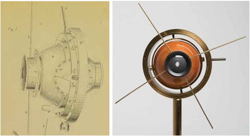
In oculomotor neurophysiology, we know Donders best for his famous law describing the possible orientations of the eye. The concepts behind Donders’ law and Listing’s law (LL) often lead to considerable confusion among students. This also bothered Donders (page 54 in Ref. Citation2), and to that end he designed and built his “phaenophthalmotrope” (from φαίηω = making visible, οφϑαλμοσ = eye, and τροπη = turn; see ).
Figure 1. Original drawing of the phaenophthalmotrope, obtained from Donders’ 11th year reportCitation2, in which he explains how the instrument can be used to illustrate the concept of “pseudotorsion,” which is a result of the coordinate system on a rotating globe, projected onto the Cartesian coordinates of the external world (see the paper by Herb Simonsz and Nick Wade, this issue). The instrument was built in different versions, like the one shown on the right, and was used by his students to learn about Donders’ law, and how to verify its validity by comparing the orientation of after images with earth-fixed vertical lines, when looking at tertiary positions.
In physics, a freely rotating rigid body has three degrees of freedom, and its orientation can be quantified by a horizontal angle, a vertical angle, and a torsional angle (the so-called Euler angles), relative to some starting position, for which all angles are zero (the primary position). Unfortunately, as these three angles are obtained by a series of rotations around three different (nested) axes in a gimbal system, the order in which these rotations are performed (i.e., the precise construction of the gimbal) determines the values of the respective angles. Thus, although the different possible rotation triplets (gimbals) can all specify the same 3D eye orientation, they each yield different values for these angles, including torsion.
Donders’ law, however, states that “with the head erect and looking at infinity, any gaze direction has a unique torsional angle, regardless the path followed by the eye to get there.” Donders’ law thus states that the orientation of the rotating eye has only two degrees of freedom, which are fully specified by its gaze direction. Ruete had nicely demonstrated this law by quantifying the perceived orientation of the green after image of a red cross projected on the fovea, while directing the eye to different secondary and tertiary eye positions.Footnoteb
Because the value (and even the sign) of the torsional angle depends heavily on the selected gimbal (which is the descriptive coordinate system), it has become known in the literature as “pseudotorsion” (see ). This mathematical fact (and inherent ambiguity) has been cause for considerable confusion among researchers, physiologists, and psychophysicists alike, up to this day.
Figure 2. (a) Pseudotorsion arises when specifying an eye position in Listing’s plane through a nested 3D gimbal system, in which only the first axis is head-fixed, and the other two axes are eye-fixed. In the Helmholtz gimbal, the head-fixed axis is horizontal, in the Fick gimbal, it is vertical. (b) In a fully head-fixed system, the eye orientation can be specified by a single-axis rotation around an axis, r, which is perpendicular to the primary and final gaze directions. Listing noted that it is confined to a plane, called Listing’s plane (LP) by his contemporaries, and the primary position is perpendicular to this plane. Listing’s law, hence, states that all torsional components of the eye-position axes are zero: rx = 0. (c) However, when making an eye movement between two tertiary eye positions in LP, here indicated by r1 and r2, the brain needs to select a rotation axis, q, that tilts out of Listing’s plane by angle ψ, according to the so-called “half-angle rule.”Citation3 This axis, therefore, will typically have a true torsional component, although all eye positions during the eye movement remain in LP. It can be shown that the eye positions then follow a straight trajectory in LP, indicated by the difference vector, d = r2−r1 (see ).
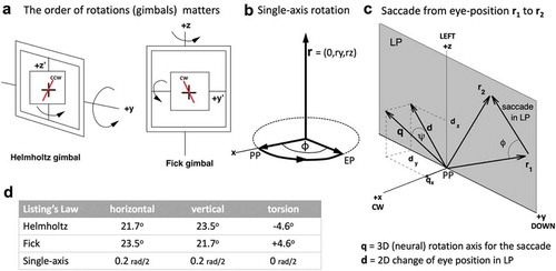
Figure 3. Listing’s law, illustrated for 3,500 eye orientations made by a head-restrained monkey, freely looking around in the laboratory room. Eye movements were measured with the scleral search-coil technique, providing a resolution of 0.1°, or better. Eye fixations are represented by the head-fixed Cartesian components of the 3D rotation axes, expressed in half-radians, but are here shown as angles in degrees, for convenience Citation4 (calculated as angle = 2・arctan(component)). For example, a component of 0.1 half-radians equals a rotation of 11°. The cross at (0,0,0) corresponds to the primary position (PP). Note that the primary position is about 20° upward with respect to the center of the oculomotor range (found at about ry = +0.2, and roughly corresponding to the straight-ahead viewing direction of the animal). The PP has to be determined experimentally from data such as these. Inset in (b): example of a particular eye position, EP, represented by its rotation axis, rEP = (0, −0.2, +0.3), and corresponding to a tertiary position in Listing’s plane of 23 deg upward, and 33 deg left from the primary position.
) shows the two most often-used gimbal systems to describe the 3D orientation of the eye; the table in ) shows the required coordinates for an eye position in Listing’s plane (LP) (described below), when gazing at approximately 21 deg left, and 21 deg downward. The gimbal system used by Helmholtz (and mentioned in Ref. Citation2) first rotates the “hypothetical eye” about a head-fixed horizontal rotation axis to indicate the vertical gaze angle, and then about the nested eye-fixed vertical axis, to attain the required horizontal gaze angle. The final rotation of the cross around the line of sight then needs to be made in the counter-clockwise direction of −4.6° to comply with LL. In the Fick gimbal, the order of the horizontal and vertical axes is reversed, leading to three (!) different values for the same eye orientation. Note, specifically, that the final rotation around the line of sight now should be clockwise over +4.6°! This is the amount of pseudotorsion, which differs by more than 9° for the two systems. Clearly, the real eye does not act as a hierarchical gimbal, and it is therefore much more appropriate to describe eye orientations in a fully head-fixed reference frame. This is the idea behind Listing’s observation.
The German mathematician Johann Benedict Listing realized that any orientation of the eye can be most efficiently described by a single-axis rotation from the primary position (PP) ()). In other words, to specify the eye’s 3D orientation it suffices to provide the three (head-fixed) coordinates of this hypothetical rotation axis: r = (rx, ry, rz) (see ) and the inset in )). In this way, the torsional component of the rotation axis (rx) will be called the true ocular torsion (positive is clockwise). The vertical component of this axis, rz, specifies the horizontal eye direction (positive is leftward), whereas its horizontal component, ry, determines the vertical gaze direction (); positive is downward).
In ), the same eye orientation, as indicated in Table 2D for the Helmholtz and Fix gimbals, is then represented by a head-fixed single-axis rotation from the PP. Listing proposed that Donders’ law could be further constrained by the fact that the rotation axes corresponding to all possible eye orientations lie in a plane LP, and that the primary gaze direction points perpendicular to this plane, i.e., along the x-direction. In this description of eye orientations, the rotation axes all have zero torsion. This leads to the most succinct formulation of LL: rx = 0. Thus, instead of specifying three angles around some arbitrary selection of gimbal axes, 3D orientations of the eye are uniquely described in a head-fixed Cartesian coordinate system of single-axis rotations that bring the eye from the PP to the current orientation.
shows two orthogonal views of measured rotation axes for 3,500 eye fixations of a head-restrained macaque monkey.Citation4 It is immediately clear from these high-resolution data that the eye fixations align very precisely with a plane, as the torsional components of these axes (side view) scatter with a standard deviation of only 0.6 deg around zero torsion.
One final remark concerns the distinction between eye positions (orientations) and actual eye movements. To describe eye orientations, as done so far, one uses a hypothetical rotation of the eye from the PP to the current orientation. The axis, needed to describe this hypothetical rotation, lies in LP (). However, true oculomotor behavior will rotate the eye from any arbitrary tertiary initial position to any other tertiary final position, without ever hitting the PP! Yet, as shows, during the movement, all eye orientations remain in LP.
So, the question arises, about which true axis the eye should rotate in order to keep the eye in LP during the entire movement. It turns out that this axis is not confined to a plane! This problem was not discussed by Donders and his colleagues in the nineteenth century, who could not measure the actual movements of the eye at high-speed resolution, but it has been a topic of intense research from the end 1980s of the 20th century, onward (e.g., Ref. Citation4) ) illustrates how to think about this problem (it unfortunately requires some mathematical background to get the numbers right, see Ref. Citation3). It turns out that the true rotation axis of the eye, q, will typically have a torsional component, rx ≠ 0, which depends on the initial eye position, r1 and the saccade vector, d, which brings the eye to the final eye position, r2Citation4
The major controversy, debated up to this day, is whether this true rotation axis is fully programmed by the brain (i.e., LL is due to “software”), whether it is magically determined by the pulleys of the extraocular muscles (LL is caused by “hardware”), or perhaps by a compromise that somehow embeds both factors.Citation4 In any case, it should be realized that LL only holds for eye movements with the head erect and gazing at infinity. For active eye-head movements, vergence eye movements, vestibular eye movements, and eye-movements under tilted head orientations, LL no longer holds. Taking the full repertoire of ocular motility into account, it seems hard to reconcile 3D eye-movement control and LL as a pure “hardware” property of extra-ocular muscles and pulleys, especially since LL only holds for a very particular (even artificial) behavioral condition.
In summary, the absence of true ocular torsion for eye fixations in Listing’s coordinate system, ()), the concept of “pseudotorsion” as observed in Ruete’s after-image experiments and nicely illustrated by Donders’ phaenophthalmotrope (, ), as well as the eye-position dependent tilt of the true rotation axis of the eye out of LP during active eye movements, like saccades and smooth pursuit ())Citation3,Citation4, have all been topics for lively discussions and controversies regarding the physiological vs. orbital-mechanical origin of LL, about its putative function for visual-oculomotor behavior, and about the control principles underlying the 3D rotational kinematics of the eyes in general.Citation4
It is interesting and amusing to see that many of these discussions and controversies were equally lively, and of a high intellectual standard, between F.C. Donders and his contemporaries. Citation2
Notes
a “… dat de behandeling van alle lijders, zonder uitzondering, kosteloos geschiedt, en dat bovendien de geneesmiddelen, de operatieve hulp, en, zoo nodig, ook de optische middelen, de kunstoogen enz. gratis worden verstrekt. …. Teeken noch bewijs, dat zij tot de minvermogenden behooren, wordt van de lijders gevorderd. ’t Is genoeg, dat ze ooglijders zijn … De stichting is dus uitsluitend instelling van liefdadigheid.”
b Donders’ law in his own words, on page 58 of Ref. Citation2: “Ik overtuigde mij verder, gebruik makende van de nabeelden van een verticalen band, dat, voor elke bepaalde richting der fixatie-lijn, in betrekking tot het rechtstandigen hoofd, langs welke omwegen die richting mocht zijn tot stand gekomen, de stand van den verticalen meridiaan, en daarmede die van het geheele oog, steeds onveranderlijk dezelfde was.”
References
- Roelofs A. One hundred fifty years after Donders: insights from unpublished data, a replication, and modeling of his reaction times. Acta Psychol (Amst). 2018;191:228–233. doi:10.1016/j.actpsy.2018.10.002.
- Donders FC. Elfde jaarlijksch verslag betrekkelijk de verpleging en het onderwijs in het Nederlandsch Gasthuis voor ooglijders [The 11th yearly report of the Netherlands Hospital for Necessitous Eye Patients]. Van de Weijer PW. Utrecht, the Netherlands, pp. 1-195, 1870 (in Dutch).
- Haslwanter T. Mathematics of three-dimensional eye rotations. Vision Research. 1995;35:1727–1739.
- Van Opstal AJ, Hepp K, Hess BJM, Straumann D, Henn V. Two-, rather than three-dimensional representation of saccades in monkey superior colliculus. Science. 1991;252:1313–1315.