ABSTRACT
In self-lubricating sliding contact facilitated with polytetrafluoroethylene (PTFE) composites, the anisotropy in tribological performance was often attributed to the oriented structures of the polymer. However, in this research, it is found that the non-homogeneity introduced by the hard fibres or stiffeners may be the main contributor to the anisotropic tribological performance of the polymeric composites. The interaction between the non-uniformly arranged hard fibres/stiffeners and the metallic counterface was found to be the leading phenomenon of this tribological behaviour. Moreover, the effects from a surface texturing scheme was found capable of establishing intervention to this interaction and reducing the anisotropy. The mechanism of the texturing effects was found related with back-transfer of PTFE and trapping of wear debris.
Graphical abstract
1 Introduction
Anisotropy in tribological performance, as a special characteristic of certain tribo-pairs, has seen constant interest of research. As early as sixteenth century, the anisotropic tribological behaviour was first observed and recorded on Iceland spar – a natural crystal of calcite, as variations in the level of resistance and cut morphology were experienced when it was scratched by a knife along different directions [Citation1]. This phenomenon was then associated with the highly oriented crystallographic structure of Iceland spar. Similarly, natural material such as wood and bamboo also exhibit anisotropic tribological performance due to the singularities in their constitutive structures [Citation2,Citation3]. Among these, the anisotropic tribological performance of the sliding contact can all be attributed to structural non-homogeneity – be it in micro or macro scale.
In modern engineering, the last few decades have witnessed a rapid development in polymeric material and their composites, which may have intrinsic anisotropic properties. As they become widely employed as contact components for their characteristics such as self-lubricating and lightweight, attention has also been attracted on the anisotropy in their tribological performance. For polymeric material, the anisotropy is often associated with the structure of the polymer at molecular level. For instance, friction on polydiacetylene monolayers was at maximum when sliding direction was perpendicular to the oriented polymer backbone axis, but at lowest when the sliding direction and the backbone was in parallel, as found by Carpick et al. through experiments [Citation4], and explained by the anisotropic stiffness of the thin film. Moreover, ultra-high molecular weight polyethylene (UHMWPE), a self-lubricating polymer widely used in prosthetic joints, anisotropy was found as the tribological performance vary greatly from linear sliding to multi-directional sliding [Citation5]. This behaviour was attributed to the stress-induced preferential orientation of softening (featured with micro-ripples and micro-crack on the sliding surface) [Citation5,Citation6]. Therefore, in laboratory studies, for consideration of the anisotropic tribological performance, an extra motor was employed to constantly rotate the composite pin during its reciprocating strokes (in pin-on-plate set-up) or revolutions (in pin-on-disc set-up) [Citation7–9], obtaining a general average of the tribological performance under all different sliding directions. Later on, international standards for polyethylene composite prosthetic joints [Citation10,Citation11] require that the kinematics tested on wear simulators should mimic the motion of joints in human gaits, involving evolution of sliding path in different motions, e.g., in flexion–extension and external-internal rotation of hip joints. Following this model, not only the a more accurate wear rate would be reflected, the wear contour and depth would also be closer to reality [Citation12]. Compared with polyethylene, PTFE (polytetrafluoroethylene) is considered as a high- performance self-lubricant due to its higher thermal stability, inert to chemical reaction and superior frictional performance [Citation13]. In PTFE, the molecular structure is arranged in smooth molecular chains. For this special micro-structure, Tabor and Pooley [Citation14,Citation15] have revealed that the frictional coefficient of PTFE was low when sliding along the direction of the oriented PTFE molecules, but significantly higher perpendicular to the molecular chain. To rationalize this this finding, Breiby et al. [Citation16] analysed the sliding surfaces with grazing incidence x-ray diffraction (GIXRD) and found that the low friction along the molecular backbone was a result of the PTFE transfer film, which has a high degree of molecular alignment. This explanation was then supported by Jang et al. [Citation17] using molecular dynamics (MD) simulation.
Given the frictional properties of the polymers, many composites have been developed by introducing other components (e.g., glass and aramid fibres), aiming at improving specific properties (e.g., wear and temperature resistance). For composites, the inherent heterogeneity in material composition facilitates possibility in anisotropy. To study the orientation-dependence of an epoxy-filled carbon fibre composite, Godet and Play [Citation18] first studied the frictional behaviour of the composite under different three-dimensional orientations, finding that the optimal frictional performance occurs when the carbon fibres were aligned perpendicular with the sliding direction and parallel with the counterface plane. Friedrich et al. [Citation19–22] also conducted a series of studies and formed a catalogue of anisotropy with fibre-reinforced polymer composites and the leading causes, including oriented fracture-propagation, reinforcing effect and variation of wear mechanism etc. For theoretical analysis, there has been the willingness to directly correlate the anisotropy in tribological performance with basic mechanical properties (e.g., elastic modulus and strengths [Citation23]) of the composites. For instance, Ning et al. [Citation24] built a strength-based model to predict the anisotropic wear behaviour for unidirectional continuous fibre-reinforced-polymer (FRP) composites. However, in the experiments from Godet & Play [Citation18] and Rasheva [Citation25], the direction-dependence of friction and wear of FRP composites has not been found directly linked with elastic modulus or tensile/compressive strength. Instead, the anisotropic hardness of the composites was intrinsically an explicit index of the tribological performance in different orientations, as has been proved in several metal matrix composites (MMC) reinforced with unidirectional fibres [Citation26]. From this aspect, it should be noticed that properties like elastic modulus only reveal the bulk properties of the material, while tribological performance is more related with the surface properties. More importantly, the complexity for the analysis of anisotropy in polymeric composites also lies on that the tribological performance can be influenced by different components. To take the epoxy composite as an example again, when reinforced by long aligned carbon nanotubes (ACNs), it was found that a conjoined effect of high-strength carbon fibre and ductile aramid fibre was the leading cause for its outstanding tribological performances in normal sliding direction [Citation21].
However, it is noticed that the discussion on the anisotropic effects from added elements in certain polymeric composites is lacking. For instance, for PTFE, many composites (e.g., glass-fibre filled or interwoven [Citation27,Citation28]) have also been developed for more demanding scenarios (e.g., the spherical plain bearings in aerospace applications), but despite the studies conducted on the anisotropic tribological performance of PTFE composites [Citation29–31], the analysis tend to focus on anisotropic effects from PTFE itself, probably due to the well-established theories stated above. Meanwhile, the effects from other components in the composites, as to whether they may act synergistically or antagonistically (regarding the anisotropy in tribological performance) with the polymer in has not been considered. To address it, the analysis for the anisotropy in tribological performance of PTFE composites needs to be more comprehensive, including the overall contributing factors from the composite constitutes.
Moreover, apart from polymeric materials and composites, conventional metallic surfaces can also exhibit anisotropic tribological performance – despite the isotropic material properties, metallic surfaces can also possess non-homogeneity in the form of topographic features. For instance, on steel surfaces processed to obtain roughness pattern that are apparently oriented, such as the micro-grooves created by machining process like turning and grinding, sliding perpendicular to the micro-groove orientation has been found to result in a considerably larger friction and wear rate than sliding in parallel [Citation32,Citation33]. This behaviour can be explained by the extra hysteresis resistance (caused by repeated change of compressing and decompressing on the surface) when the sliding occurs transversely [Citation34]. The anisotropy led by the oriented topographic features, however, is normally only apparent in running-in period when the micro asperities have not worn out [Citation35]. Similar to surface roughness, surface textures, which are well controlled surface patterning produced by process such as laser texturing [Citation36] and masked etching [Citation37] can also lead to anisotropic tribological behaviour in certain forms. Evolving from Hamilton’s concept of micro-dimples [Citation38], surface texturing have seen developments and industrialized applications in seals (with laser texturing [Citation36,Citation39]), cylinder liners (with cross-hatch honing [Citation40]) and hard-slider disks (with focused ion-beam [Citation41]) etc., and have now become increasingly popular for their bespoke topographic characteristics. Apart from achieving certain common effects such as lubricant reservation [Citation42,Citation43] and contact pressure alteration [Citation44–46], surface textures have also been applied to establish anisotropic tribological behaviour, such as directional friction [Citation47–49].
Recently, increasing number of surface texturing patterns have been tested effective in improving tribological performance of PTFE-metal contact [Citation50–52], with the mechanism of the surface textures in polymeric bearings often attributed to the reservation effect on the transfer film. However, among the studies on the texturing effects for PTFE, the discussion on the impact of anisotropic tribological performance seems missing. Given that in the sliding contact between a polymeric material and textured metallic surface, both surfaces possess a type of non-homogeneity, it is worth discussing how they would interact – whether the texturing effects may vary with the orientation of the polymer composite, and whether surface textures may in turn influence the anisotropy of the self-lubricating system. To understand the interaction between the texturing effects and the anisotropic tribological performance can add knowledge to this novel contact problem, but to date, the investigation of this topic is still lacking.
In this article, to fill the research gap discussed above, the anisotropy of a PTFE composite sliding against a smooth and a textured counterface was studied experimentally. Attention was given to the overall pictures of the tribological behaviour led by the composite instead of solely focusing on the polymer for analysing the anisotropy. Moreover, based on a comprehensive surface analysis series applied to identify the difference in the fundamental tribological phenomenon encountered with smooth and textured counterface, a theoretical scheme was proposed to explain the influence of the counterface texturing to the anisotropy in the tribological performance.
2 Test methodology
In order to investigate the anisotropy in the tribological performance of the PTFE self-lubricating composite, pin-on-plate wear tests simulating the sliding contact between the two component surfaces (i.e., sphere surface in PTFE composite and sleeve surface in steel) were conducted with the composite aligned in different orientations.
2.1 Sample preparation
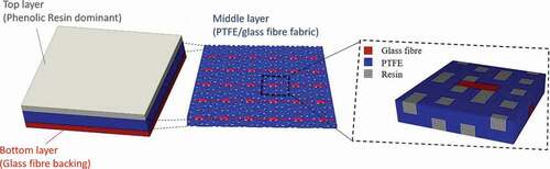
The pin sample used in the wear test was the X1 PTFE/glass fibre composite (manufactured and provided by SKF), which has been widely used as the bearing liner in modern helicopter rotor-heads. As shown in , the composite is a multi-layer composite, in which its middle part (along thickness direction) is a special 2D interwoven fabric of glass fibre and PTFE impregnated and bounded by phenolic resin. Moreover, the resin/PTFE dominant top layer and the glass-fibre dominant bottom layer correspond to the initial stage and final stage when the composite wears. For the sliding wear tests, the samples had the same thickness (280 µm) and square surface area (7 mm×7 mm), and were bounded onto the steel backing with the phenolic resin through the standard manufacturing process for aerospace rod-end bearings conducted in SKF UK Ltd.
Figure 1. Structure of the composite with highlight in the middle layer of PTFE/glass fibre fabric.
Two sets of counterface – one smooth and one textured are prepared for the sliding wear tests. The counterface material is the AMS5630 440 C stainless steel. In its original smooth state, it has the surface hardness of 56 HRC and the average surface roughness at around Rq 0.020 µm.
A dimpling pattern (dimple diameter 20 μm, depth 2 μm) was adopted on texturing the counterface, and the coverage of the textures was set as 1.6%, which was capable to effectively influence the tribological performance in this contact scenario (at larger dimensions or coverages the textures would simply act as micro-abrasives) according to the previous related study [Citation52]. Although in the previous study, certain boosting effects (i.e., reserving transferred PTFE) from counterface texturing had been found with the composite fixed at a single orientation (45°), this test series was designed to find out whether the effects from texturing might vary with various composite orientations, and whether the anisotropic/isotropic tribological performance may be influenced by the textures.
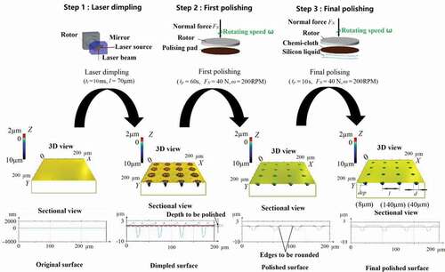
To generate the bespoke dimple pattern (dimple diameter d = 20 μm, depth dep = 2 μm and area coverage pc = 1.6%), laser surface texturing (LST) and a two-step polishing process were adopted. As demonstrated in , the original surfaces were firstly ablated by Ekspla AtlanticHE 1064 picosecond pulsed laser (pulse duration 50 pico-seconds, wavelength of 1064 nm and estimated peak fluence 73.98 J/cm2) at evenly spaced points (distance = 40 μm) for the same dwelling time (4 milliseconds). Then, the surfaces experienced an initial polishing (with Struers LaboSystem machine and a polishing cloth with 1 µm-diameter grits) to remove the inherent material re-deposition, and a final polishing (with MetPrep final polishing cloth and 0.05 µm silica suspension) to round the dimple edges.
Figure 2. Processing scheme for manufacturing the textured surface.
As a result of the two-step polishing, the achieved surface roughness of the textured samples reached a level lower than the original surfaces (Rq 0.015 µm). Therefore, the un-textured steel samples, which would be used as the reference smooth surfaces, were put under the same batch for the two polishing steps to acquire the same surface roughness.
2.2 Sliding wear test
To simulate the relative sliding between the PTFE composite and the counterface in the pitch-control bearings of the real helicopter rotor-heads, linear reciprocating motion is produced through the crank-slider system in a modified BICERI universal wear test machine (). The measurement of the friction force was performed using two full bridges of strain gauges (Vishay L2A-06-062LW-120) bonded on the rectangular shear frame, as shown in ). For the wear rate, in order to achieve a continuous measurement without interruption of the tests, a Linear Variable Differential Transformer (LVDT) was implemented vertically, with its probe in contact with a reference plane at the bottom to measure the descending of the lever incurred by the wear of the liner.
Figure 3. Images of (a) set-up of the reciprocating sliding wear rig and (b) detailed view of the contact and measurement.
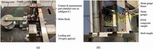
As revealed by a pre-study [Citation53], in which real flight operating data of a helicopter was input to the rotor kinematics, the sliding paths of a spherical plain bearing (e.g., a pitch-control-bearing) have a rather narrow distributing spectrum, centralizing on a main sliding direction (~5.0° deviated from the sleeve circumferential in the case analysed). Considering this, linear reciprocating motion was produced using the crank-slider set-up (as shown in ) in the rig for a more realistic simulation of the relative sliding between the contact surfaces. Then, to investigate the tribological performance of the bearing with the PTFE composite liner bonded in different orientations (e.g., 0º, 45º, 90º, 135º like shown in ) on the sleeve, the composite was aligned in four representative orientations (corresponding to ) relative to the reciprocating sliding direction of the pin-on-plate set-up, as demonstrated in .
Figure 4. Schematic demonstration of the composite aligned at (a) 0°, (b) 45°, (c) 90°, and (d) 135° relative to the main sliding direction in the spherical plain bearing.
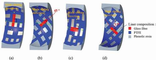
Table 1. Test matrix for wear tests on different counterface types and composite orientations
In the tests conducted, the rotating speed of the rotor was set at 180 RPM (i.e., 3 Hz reciprocating frequency), and the reciprocating stroke length was set as 20 mm. As for the load, a 196 N normal force was applied using weights. With this set-up, the pressure-velocity factor achieved (average sliding speed 0.12 m/s, and nominal contact pressure 40 MPa) mimicked those occurring in the spherical plain bearings of the real helicopter rotor-heads.
2.3 Surface analysis
To analyse the different wear behaviour from varied composite orientations in the sliding wear tests, the FEI Quanta 650 ESEM was used to acquire SEM images of the contact surfaces (both the composite liner and the counterface), employing the Backscattered-Electron (BSE) imaging with optimized low-accelerating-voltage established in previous study [Citation52] for identifying PTFE transfer. Meanwhile, the Bruker Contour GT-I 3D Optical interferometer was employed to obtain the topographic information of the counterface. The analysed surfaces have undergone around half-way (i.e., in steady wear stage) of the full wear tests, and were coated with around 10 nm of carbon-coating (to increase conductivity) prior to SEM analysis.
3 Test results and analysis
3.1 Friction and wear performance
To focus on the comparison of the performance between different composite orientations, for each condition, the representative friction and wear curves (selected from at least three repetitions which are summarised in in the Appendix) were plotted in two groups – with composites in varied orientation angles on smooth counterface () and with dimpled counterface.
Figure 5. Measurement of (a) CoF and (b) wear progression for comparison between composite with different orientations sliding against a smooth steel surface (Rq 0.015 µm).
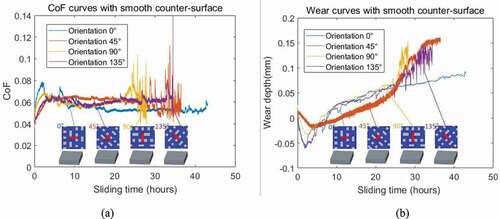
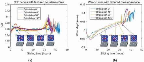
Figure 6. Measurement of (a) CoF and (b) wear progression for comparison between composite with different orientations sliding against a dimpled steel surface (dimple depth 2 µm, diameter 20 µm, coverage 1.6%).
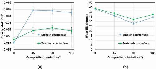
Firstly, with smooth counterface, in terms of the coefficient of friction (acquired as the mean CoF value in the steady-state phase) and wear life (identified as the time till the total wear-out of the composite liner), an optimal angle – 0° and an undesirable orientation – 90° can be identified, as shown in . It can be observed that at the orientation of 0° the PTFE composite had a wear life around 44 hours, exceeding the 90° scenario (around 30 hours) by around 50%. In addition, the steady-state CoF with 0° orientation was around 0.053, considerably lower than that of 90° (around 0.062). Meanwhile, for the other two tested orientations (45° and 135°), the steady-state CoF value was similar with 90°, but the wear life fell in-between the 0° and 90° cases. Overall, the tribological performance was outstanding orientation at 0°, but considerably inferior at 90°. Since this fabric pattern contains similar amount of PTFE orthogonal wefts and warps (represented in blue), these components should induce minimal effect for a 90° orientation change, and therefore should not be the main cause for the significant anisotropy observed. Meanwhile, since the glass fibres (represented in red) are all oriented in one direction in the composite (as longitudinal warps in the unit pattern), and sliding in different angles against an oriented topographic feature was reported to yield varied tribological performance [Citation32,Citation33], the geometry of these hard fibres (close to an elliptical bar) could be a cause of the anisotropy. However, theoretically after the running-in period the top of the glass fibres became flattened out, the difference between parallel (0°) and transverse (90°) sliding should be minor. In fact, significant difference in CoF and wear rate still existed in steady stage as well. Therefore, further analysis is needed to find other possible causes for the anisotropy.
As for the cases with dimpled counterface, the anisotropy in both CoF and wear life had similar patterns with the smooth cases among the four orientations, as in . However, the performance was slightly lifted with each conditions while the gaps between them were moderately reduced. On one hand, the steady-state CoF for all orientations met at around 0.055 despite the small difference (maximum around 0.003) in the earlier period (from 6 to 15 hours). On the other, for wear life all four orientations saw a small improvement, which should be attributed to the reformation of transfer-film by dimples according to the previous study [Citation52]. However, the extension on wear life with 90° orientation was a remarkable 3–5 hours (from the three repeated tests conducted), but the effect on the 0° case was marginal (no more than 1 hour), indicating that the gap between different orientations was narrowed to some extent because of surface texturing. Theoretically, the surface textures have the functions of reserving PTFE transfer and wear debris, and alter contact stress. However, none of these seems to be directly linked to this relieving effect on the anisotropy, particularly the origin of the anisotropy has not been confirmed. Therefore, analysis on the detailed tribological phenomenon occurring during the sliding contact is needed to identify the mechanism.
To sum up, these test results indicated a connection between the tribological performance (particularly in overall wear life) and the orientation of the composite, with 0° being the optimal and 90° being the least favourable. The ranking of the orientations did not vary when counterface textures were introduced, but the difference between them would be reduced. To explain the findings, the following analysis were conducted, aiming at relating these differences with the intrinsic feature of the composite – non-uniform material distribution, and the changes incurred by counterface textures.
3.2 Surface analysis
In order to identify the phenomenon leading to the anisotropy in tribological performance of the composite liner sliding against steel counterface, SEM analysis and surface topographic imaging were conducted on the resultant surfaces acquired in tests around half-way through the steady-wear stage. Meanwhile, comparisons were also conducted between the conditions with the smooth and textured surfaces to investigate the influences from the surface texturing.
3.2.1 Surface analysis on the counterface
3.2.1.1 Analysis on the smooth counterface (for the cause of anisotropic tribological performance)
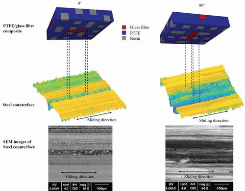
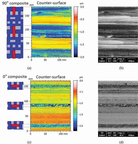
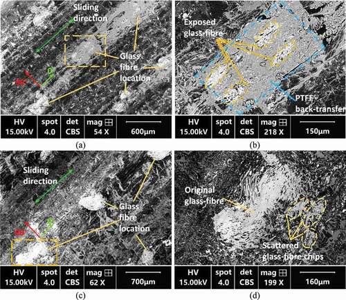
First of all, on the smooth counterface, the two main phenomenon observed were the strip-patterned wear tracks (low valleys in the topographic images), and the ‘thick’ PTFE transfer film (dark areas in the BSE images). What should be noted in this observation was that only the thicker form (micro-metre level) of the PTFE transfer layer was characterised in the BSE images due to the observation scope of the SEM (limited by its penetration depth), while PTFE should also transfer over the entire counterface as uniform monolayer thin film. For those ‘thick’ PTFE transfer layers, mostly they appear on the abrasion tracks, which should be led by the glass fibre woven in the composite judging by the location-matching, as shown in . Therefore, as the projection areas of the glass fibres to the sliding path vary with the altering of fibre orientation, the resultant abrasion tracks differ in widths – the most prominent pair being the composite aligned at 0° and 90°, comparing . During the sliding contact, the drastically-rougher abrasion tracks (Rq>0.4 µm as measured) would act as extra abrasives and cause a considerably higher wear and friction than the non-abraded surface areas. Besides, for PTFE fibre arrangement in the composite, even though every PTFE fibre itself may establish anisotropic tribological behaviour [Citation14,Citation15], the PTFE fibres were interwoven perpendicularly both as wefts and warps in similar content in the composite (as in )), thus should establish similar tribological performance overall regardless of the composite orientation. In all, the varied extent of abrasion with different fibre orientations should be the main cause leading to the different tribological performance in these two aligning orientations. Since the abrasion wear tracks are drastically rougher (Rq>0.4 µm as measured), they would cause a considerably higher wear rate and friction than the smooth counterpart. Even though as indicated by ), PTFE transfer were also contained in the wear-track-regions, the maintaining of it would be constantly affected by the scratching of glass fibres and the as well as the debris. Judging by the test results that orientation of 90 ° saw the worst wear performance and 0° had the best, the benefit in transfer film in wear-track-areas certainly had not exceeded the drawback of abrasion.
Figure 7. (a) Topographic image and (b) SEM image (BSE) of the counterface (initially smooth) half-way through the wear test with composite oriented at 90°; (c) topographic image and (d) SEM image (BSE) of the counterface (initially smooth) half-way through the wear test with composite oriented at 0°.
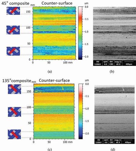
As for the other two orientations (45 ° and 135 °), the resultant widths of abrasion tracks (in-between the widths generated with 0° and 90° orientations) were similar as the fabric patterns were basically symmetrical against the sliding path, as shown in , c). Relating this observation with their tribological performance (mainly wear life) which was also similar (better than the 90° orientation and inferior than the 0° as revealed in chapter 3.1), the conclusion that the anisotropic tribological performance was caused by the varied abrasion extent can be further supported.
Figure 8. (a) Topographic image and (b) SEM image (BSE) of the counterface (initially smooth) half-way through the wear test with composite oriented at 45°; (c) topographic image and (d) SEM image (BSE) of the counterface (initially smooth) half-way through the wear test with composite oriented at 135°.
3.2.1.2 Analysis on the textured counterface (for the influence of counterface textures)
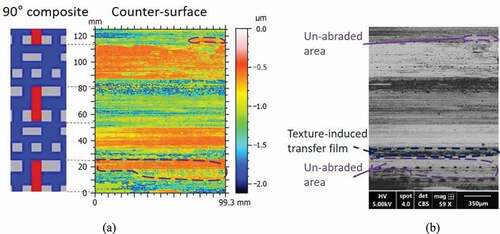
In comparison, for textured counterface, while the basis physical phenomenon occurring on the surfaces generally resembled that on smooth counterface, differences existed on the detailed distribution of wear track areas and transferred PTFE. On one hand, on the counterface, as shown in with 90° composite orientation, certain un-abraded areas, or areas with little abrasion were observed (all marked as ‘un-abraded area’) within the abrasion-track-region. On the other, more ‘thick’ PTFE transfer film was observed outside the abrasion-tracks (i.e., areas not in contact with the glass fibres). Judging by the film morphology along the dimple arrays, the layer should be the one induced by the reservation and redistribution effects from the dimples, like has been shown in the related previous study [Citation52].
Figure 9. (a) Topographic image and (b) SEM image (BSE) of the counterface (initially textured) half-way through the wear test with composite oriented at 90°.
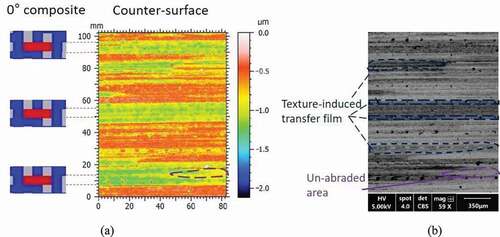
With composite aligned in other angles, similar effects on the abrasion areas and ‘thick’ PTFE transfer can be can be seen, but in different degrees. For instance, with 0° composite orientation, the boost in ‘thick’ PTFE transfer in areas was much more prominent, as marked in . Meanwhile, little was found as smooth areas emerging within the abrasion tracks. This difference was probably due to that the abrasion tracks were narrower, while the areas not abrade by the glass fibres were much wider in this case. Moreover, the difference in the extent of the effects from counterface texturing helps explain why the same texturing pattern can create varied level of influence on the tribological performance, as illustrated in chapter 3.1.
Figure 10. (a) Topographic image and (b) SEM image (BSE) of the counterface (initially smooth) half-way through the wear test with composite oriented at 0°.
In conclusion for the analysis on the counterface, the main cause to the anisotropic tribological performance of the PTFE/glass fibre composite was the orientation-dependent wear track areas resultant on the counterface. Meanwhile, the abrasion tracks were accompanied with the ‘thick’ PTFE transfer. Both phenomenon were well-patterned following the material distribution in the composite, but the dimpled counterface can influence the pattern to a certain degree, yet the mechanism behind the dimples’ effects needs to be further analysed.
3.2.2 Surface analysis on the PTFE composite surface
To supplement analysis on the tribological phenomenon occurring on the interface, and to seek for a more comprehensive explanation of the texturing effects, SEM analysis (with EDX for elemental analysis) was also conducted on the PTFE composite surfaces.
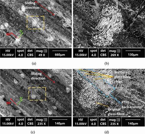
With SEM images of the composite surfaces, a phenomenon that leads to the smoothening effect within the abrasion tracks with dimpled counterface was observed. As shown in ), when the counterface was textured, strips of PTFE back-transfer (marked as ‘PTFE back-transfer’, verified by EDX analysis) were reserved on the composite surface (0° orientation).
Figure 11. (a) SEM image (BSE) of the composite surface (oriented at 0°) sliding against smooth counterface and (b) a magnified view on the glass-fibre area; against (c) SEM image (BSE) of the composite surface (oriented at 0°) sliding against dimpled counterface and (d) a magnified view on the glass-fibre area.
However, for the case with smooth counterface, as shown in ), little back transfer was observed. Meanwhile, more fragments of glass fibres were even found scattered over the composite surface encountering smooth counterface.
Similarly, with 90° composite orientation, like shown in , the back-transfer was more prominent with dimpled counterface. Moreover, it can be seen that this back-transfer can serve as a protective layer, containing the abrasive wear particles from glass fibres (as marked in )), thus alleviating the generation of counterface wear track and further abrasion.
Figure 12. (a) SEM image (BSE) of the composite surface (oriented at 90°) sliding against smooth counterface and (b) a magnified view on the glass-fibre area; against (c) SEM image (BSE) of the composite surface (oriented at 90°) sliding against dimpled counterface and (d) a magnified view on the glass-fibre area.
Therefore, as revealed by the SEM analysis on PTFE composite surfaces, the two main effects from the counterface textures were the boosted PTFE back-transferring and reduced glass fibres spreading. Including thickening the PTFE transfer sheet on the counterface, these effects can actually all be attributed to the reservation function of the counterface textures. To conclude, as demonstrated in , the proposed scheme of the texturing effects is in three aspects:
Figure 13. Schematic diagram of the sliding between the PTFE/glass fibre composite and the dimpled counterface: (a) the starting state of the sliding contact; (b) the generation of PTFE and glass fibre debris from sliding contact; (c) the initial transfer of PTFE, scratching of the counterface and the reservation of debris; (d) the formation of thick transfer layer and back-transfer.
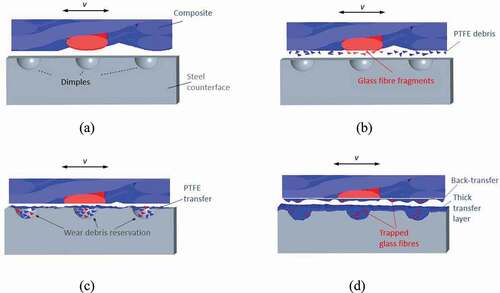
i. Reserving the PTFE debris generated in sliding contact within the dimples, thus forming thickened PTFE transfer layer;
ii. With thickened PTFE layers and more PTFE debris contained within the contact interface, inner shearing within the PTFE layer and back-transferring to the composite surface would occur more frequently;
iii. Indiscriminately, the fragmented glass fibres would also be contained by the dimples, consequently the spreading of these abrasive particles over the contact interface and further three-body abrasion would be prevented.
Linking the surface texture’s effects with its influence on the anisotropy of the tribological performance, a dual-effect mechanism can be proposed to explain its reducing function. On one hand, since the glass fibres on the composite surfaces received more ‘protection’ by the back-transferred PTFE, less fragmentation and counterface roughening would occur. Consequently, the glass-fibre incurred abrasion (the origin of the anisotropic tribological performance of the composite) would be alleviated. This postulation can be supported by the observation of un-worn counterface areas existing within the roughened wear tracks (in ). On the other hand, counterface textures would inevitably cause certain degree of extra micro-abrasions on the PTFE composite surfaces. Different from the abrasions caused by the glass fibres, the micro-abrasions led by the counterface textures would occur uniformly among the PTFE composite surfaces as with the distribution of the dimples. In other words, the overall abrasion wear with dimpled counterface should be less dependent on the glass fibre orientation and distribution in the composite, and therefore show less anisotropic behaviour.
4 Conclusion
This paper investigated the anisotropic tribological performance of a PTFE composite, and studied the influence on the anisotropy from a counterface texture pattern. It was found through the study:
- The origin of the anisotropic tribological performance of the fibre-reinforced-polymer composite can be the fibre-counterface interaction
As found that in the sliding contact between the PTFE/glass-fibre woven composite and the isotropic steel counterface, the counterface can acquire non-homogeneity (in surface topography) essentially by the non-uniform glass-fibre distribution of the composite. The roughness of abrasion track then in turn influence the wear of the composite. This cross-interaction is the mechanism leading to anisotropic tribological performance.
- A uniform pattern of counterface textures may alleviate or overwhelm the anisotropic tribological performance
When a uniform pattern of artificial non-homogeneity (the dimple texture) is introduced on the counterface, the consequent effects can intervene the fibre-counterface interaction. The beneficial back-transfer on account of the surface textures can alleviate the fibre-induced abrasion, while other texture-induced effect such as the thick PTFE transfer should also contribute to a more uniform surface phenomenon. Consequently, the anisotropy in tribological performance can be relieved.
The new finding on the origin of orientation-dependent tribological performance should incite more exploration on the improvement in polymeric composites, including optimization on the alignment orientation, choice on the reinforcing fibre (e.g., substituting glass fibres with other non-brittle material) and optimizing its proportion etc. Moreover, the finding on the texturing renders prospect for applying surface textures for modifying anisotropic tribological performance.
Acknowledgements
The authors are grateful to the support provided, and particularly the technical advice from Dr Johnpaul Woodhead in SKF UK. Ltd.
Disclosure statement
No potential conflict of interest was reported by the author(s).
Additional information
Funding
References
- Hutchins RM.Chapter Five: on the strange refractions of Iceland crystal. In: Treatise Light - Gt Books West World. London: Encyclopedia Britannica; 1952. p. 545–619.
- Vaz M, Fortes MA. Friction properties of cork. J Mater Sci. 2002;33(8):2087–2093.
- Tong T, Arnell RD, Ren LQ. Dry sliding wear behaviour of bamboo. Wear. 1998;221(1):37–46.
- Carpick RW, Sasaki DY, Burns AR. Large friction anisotropy of a polydiacetylene monolayer. Tribol Lett. 1999;7(2/3):79–85.
- Wang A, Sun DC, Yau S, et al. Orientation softening in the deformation and wear of ultra-high molecular weight polyethylene. Wear. 1997;203-204:230–241.
- Shi W, Dong H, Bell T. Tribological behaviour and microscopic wear mechanisms of UHMWPE sliding against thermal oxidation-treated Ti6Al4V. Mater Sci Eng. 2000;291(1–2):27–36.
- Joyce TJ, Thompson P, Unsworth A. The wear of PTFE against stainless steel in a multi-directional pin-on-plate wear device. Wear. 2003;255(7–12):1030–1033.
- Joyce TJ, Monk D, Scholes SC, et al. A multi-directional wear screening device and preliminary results of UHMWPE articulating against stainless steel. Biomed Mater Eng. 2000;10:241–249.
- Joyce TJ, Vandelli C, Cartwright T, et al. A comparison of the wear of cross-linked polyethylene against itself under reciprocating and multi-directional motion with different lubricants. Wear. 2001;250(1–12):206–211.
- ISO/TC 150/SC 4 Bone and joint replacements Technical Committee. ISO 14243–3:2014 Implants for surgery — Wear of total hip-joint prostheses — Part 3: Loading and displacement parameters for orbital bearing type wear testing machines and corresponding environmental conditions for test. 2014.
- ISO/TC 150/SC 4 Bone and joint replacements Technical Committee. ISO 14242–1:Implants for surgery — Wear of total hip-joint prostheses — Part 1: Loading and displacement parameters for wear-testing machines and corresponding environmental conditions for test. 2014.
- Wang XH, Li H, Dong X, et al. Comparison of ISO 14243-1 to ASTM F3141 in terms of wearing of knee prostheses. Clin Biomech. 2019;63:34–40.
- Makinson KR, Tabor D. The friction and transfer of polytetrafluoroethylene. R Soc. 1964;281:49–61.
- Tabor D, Williams DEW. The effect of orientation on the friction of polytetrafluoroethylene. Wear. 1961;4(5):391–400.
- Pooley CM, Tabor D. Friction and molecular structure: the behaviour of some thermoplastics. Proc R Soc A Math Phys Eng Sci. 1972;329:251–274.
- Breiby DW, Sølling TI, Bunk O, et al. Structural surprises in friction-deposited films of poly(tetrafluoroethylene). Macromolecules. 2005;38(6):2383–2390.
- Jang I, Burris DL, Dickrell PL, et al. Sliding orientation effects on the tribological properties of polytetrafluoroethylene. J Appl Phys. 2007;102
- Godet M, Play D. Third-body formation and elimination on carbon-fibre/epoxy composite. Sp Tribol Proc first Eur Sp Tribol. Fracasti,Italy. 1975. 165–173.
- Friedrich K, Voss H, Voss H. Effect of short fibre reinforcement on the fatigue crack propagation and fracture of PEEK-matrix composites. Composites 1986;17(3):205–216.
- Cirino M, Friedricht K, Pipes RB. Evaluation of polymer composites for sliding and abrasive wear applications. Composites. 1988;19(5):383–392.
- Wang H, Chang L, Yang X, et al. Anisotropy in tribological performances of long aligned carbon nanotubes/polymer composites. Carbon N Y. 2014;67:38–47.
- Friedrich K. Polymer composites for tribological applications. Adv Ind Eng Polym Res. 2018;1:3–39.
- Zhang F, Liu K, Wan Y, et al. Experimental and numerical analyses of the mechanical behaviors of three-dimensional orthogonal woven composites under compressive loadings with different strain rates. Int J Damage Mech. 2014;23(5):636–660.
- Ning X, Lovell MR, Morrow C. Anisotropic strength approach for wear analysis of unidirectional continuous FRP composites. J Tribol. 2004;126(1):65–70.
- Rasheva Z, Zhang G, Burkhart T. A correlation between the tribological and mechanical properties of short carbon fibers reinforced PEEK materials with different fiber orientations. Tribol Int. 2010;43(8):1430–1437.
- Hutchings IM. Tribological properties of metal matrix composites. Mater Sci Technol (United Kingdom). 1994;10(6):513–517.
- Sliney HE, Williams FJ. Performance of PTFE-lined composite journal bearings. Am Soc Lubricait Eng Present ASLE 37Th Annu Meet. Cincinnati; 1982.
- Arkles B, Theberge J, Schireson M. Wear behavior of thermoplastic polymer- filled PTFE composites. Lubr Eng. 1977;33:33–38.
- Blanchet TA, Kennedy FE. Sliding wear mechanism of polytetrafluoroethylene (PTFE) and PTFE composites. Wear. 1992;153(1):229–243.
- Lu J, Qiu M, Li Y. Numerical analysis of self-lubricating radial spherical plain bearings and investigations on fatigue damage mechanisms of the liner. Tribol Int. 2016;96:97–108.
- Lu J, Qiu M, Li Y. Wear models and mechanical analysis of PTFE/Kevlar fabric woven liners used in radial spherical plain bearings. Wear. 2016;364-365:57–72.
- Dizdar S. Wear transition of a lubricated sliding steel contact as a function of surface texture anisotropy and formation of boundary layers. Wear. 2000;237(2):205–210.
- Horng JH, Lin JF, Lee KY. The effect of surface Irregularities on the tribological behavior of steel rollers under rolling-sliding contact. J Tribol. 1994;116(2):209–218.
- Menezes PL, Kailas SV. Role of surface texture and roughness parameters on friction and transfer film formation when UHMWPE sliding against steel. Biosurface and Biotribology. 2016;2(1):1–10.
- Wang J, Whitley BW, Cusano C, et al. An experimental study of the effects of surface lay orientations on initial surface damage in point contacts. Tribol Trans. 1992;35(4):583–594.
- McNickle AD, Etsion I. Near-contact laser surface textured dry gas seals. J Tribol. 2004;126(4):788.
- Pettersson U, Jacobson S. Influence of surface texture on boundary lubricated sliding contacts. Tribol Int. 2003;36(11):857–864.
- Hamilton DBWJA, Allen CM, Allen CM. A theory of lubrication by micro-irregularities. ASME J Basic Eng. 1966;88(1):177–185.
- Etsion IKY, Halperin G. Analytical and experimental investigation of laser-textured mechanical seal faces. Tribol Trans. 1999;42(3):511–516.
- Martz BLS. Preliminary report of developments in interrupted surface finishes. J Am Soc Nav Eng. 1950;62:487–504.
- Zhou L, Kato K, Umehara N, et al. Nanometre scale island-type texture with controllable height and area ratio formed by ion-beam etching on hard-disk head sliders. Nanotechnology. 1999;10(4):363–372.
- Vilhena LM, Sedlaček M, Podgornik B, et al. Surface texturing by pulsed Nd:YAG laser. Tribol Int. 2009;42(10):1496–1504.
- Voevodin AA, Zabinski JS. Laser surface texturing for adaptive solid lubrication. Wear. 2006;261(11–12):1285–1292.
- Cupillard S, Glavatskih S, Cervantes MJ. Computational fluid dynamics analysis of a journal bearing with surface texturing. Proc Inst Mech Eng Part J J Eng Tribol. 2008;222(2):97–107.
- De Kraker A, Van Ostayen RAJ, Van Beek A, et al. A multiscale method modeling surface texture effects. J Tribol. 2007;129(2):221–230.
- Tala-Ighil N, Maspeyrot P, Fillon M, et al. Effects of surface texture on journal-bearing characteristics under steady-state operating conditions. Proc Inst Mech Eng Part J J Eng Tribol. 2007;221(6):623–633.
- Lu P, Wood RJK, Gee MG, et al. The use of anisotropic texturing for control of directional friction. Tribol Int. 2017;113:169–181.
- Ito S, Takahashi K, Sasaki S. Generation mechanism of friction anisotropy by surface texturing under boundary lubrication. Tribol Int. 2020;149:105598.
- Lu P, Wood RJK, Gee MG, et al. A novel surface texture shape for directional friction control. Tribol Lett. 2018;66(1):1–13.
- Xiong D, Qin Y, Li J, et al. Tribological properties of PTFE/laser surface textured stainless steel under starved oil lubrication. Tribol Int. 2015;82:305–310.
- Lu C, Shi P, Yang J, et al. Effects of surface texturing on the tribological behaviors of PEO/PTFE coating on aluminum alloy for heavy-load and long-performance applications. J Mater Res Technol. 2020;9(6):12149–12156.
- Ding L, Axinte D, Butler-Smith P, et al. Study on the characterisation of the PTFE transfer film and the dimensional designing of surface texturing in a dry-lubricated bearing system. Wear. 2020;448–449
- Ding L. Surface texturing on dry-lubricated transmissions and power systems to deliver better performance and simplified systems in aerospace engineering (PhD dissertation). Department of Mechanical Engineering, University of Nottingham; 2020.
Appendix
Wear test data summarised from repeated tests in each condition
Figure 14. Measurement of (a) steady-state CoF and (b) wear life of the PTFE composite sliding again the smooth and the textured counterface in different orientations.