
 ?Mathematical formulae have been encoded as MathML and are displayed in this HTML version using MathJax in order to improve their display. Uncheck the box to turn MathJax off. This feature requires Javascript. Click on a formula to zoom.
ABSTRACT
Brazing is a 5000-year-old joining process which still meets advanced joining challenges today. In brazing, components are joined by heating above the melting point of a filler metal placed between them; on solidification a joint is formed. It provides unique advantages over other joining methods, including the ability to join dissimilar material combinations (including metal-ceramic joints), with limited microstructural evolution; producing joints of relatively high strength which are often electrically and thermally conductive. Current interest in brazing is widespread with filler metal development key to enabling a range of future technologies including; fusion energy, Solid Oxide Fuel Cells and nanoelectronics, whilst also assisting the advancement of established fields, such as automotive lightweighting, by tackling the challenges associated with joining aluminium to steels. This review discusses the theory and practice of brazing, with particular reference to filler metals, and covers progress in, and opportunities for, advanced filler metal development.
The nature of brazing
Brazing creates a permanent, strong, metallic bond between (potentially dissimilar) materials. The defining aspect of brazing is the melting of a filler metal in the joint; this alloy must be capable of wetting the base metal [Citation1], and have a liquidus temperature above 450°C (to distinguish from soft soldering), but below the melting point of the materials being joined [Citation2]. In practice this distinction between brazing and soft soldering is frequently blurred; jewellers often refer to their craft as soldering while using filler metals with melting ranges substantially above 450°C, while some advanced filler metals are pushing brazing process temperatures below this boundary. Brazing presents a number of unique features compared to alternative joining technologies, such as adhesives, fasteners or welding, and, as we survey below, it can be a very versatile process.
The principal advantage of brazing when compared to other joining techniques (and one of the main attractions for its use in advanced engineering) is its capability to join widely dissimilar materials, and to do so with minimal modification of the materials being joined. Whilst welding usually provides a stronger joint, it predominantly requires similar base metals and the intensive local heating causes thermal distortion, which is avoided by uniform heating of the assembly in furnace brazing. Nevertheless, brazed assemblies will have somewhat lower operating temperatures than fusion welds, and are often weaker. The strength of brazed joints is commonly greater than the filler metal but less than the parent material. Despite this, if designed and joined correctly, brazed joints can have sufficient strength that failure occurs in the parent material [Citation2].
Brazing development
Brazing is not a recent process. It can be traced back 5000 years to Sumeria and Egypt [Citation2], where evidence exists that ancient Egyptians joined gold and silver using alloys of these metals with copper to suppress the melting temperature. Wall paintings in Egyptian tombs from as early as 1475 BC depict slaves using reed blow pipes and charcoal fires to braze gold. Since these times, increasingly complex filler metals have evolved to meet the challenges of joining more advanced materials. In the 1930s Handy and Harman in the United States developed low temperature (<700°C) silver-containing brazing filler metals (AgCuZnCd and AgCuP systems). Emerging from the Second World War, nickel-based filler metals were invented to cater for the demands of the nascent aerospace industry. Technical progress caused the joining of aluminium alloys and affixing metals to ceramics to become focus areas for development of new brazing filler metals and brazing processes, and the evolution of new materials and requirements to combine them in different ways now demand ever more of brazing.
Recent reports of brazing research include sapphire-sapphire joining for use in aircraft windows and scratch resistant engineering components [Citation3], joining of bulk metallic glasses to steel [Citation4], gold-based filler metals to join graphite to superalloy in the petrochemical and nuclear industries [Citation5], boron free-filler metals for joining corrosion-resistant steel in rocket nozzles and heat exchangers [Citation6], indium-containing alloys for SiO2f/SiO2 composite materials in antenna radomes [Citation7], and filler metals free of radiation sensitive elements (e.g. Ni and Co) for use with tungsten in fusion reactor diverters [Citation8]. As can be seen, industrially pivotal research regarding brazing continues in a multitude of different sectors. Understanding this, it is the intention of this review not to focus on the fundamentals of brazing (which are covered most thoroughly in several handbooks [Citation1,Citation2]) but to assess in detail some of the recent developments, in particular in filler metals, and to highlight the demands modern engineering has for further advancement of brazing.
Filler metals
Filler metal is the term used in brazing to describe the alloy (or elemental metal) which forms the joint. It is placed between two (or more) components (the parent materials), and having a lower melting point than them, is melted and allowed to solidify, forming a joint within a brazing assembly. Optimised filler metal selection depends on a multitude of factors including;
The materials being joined – metallurgical compatibility between filler and parent metals
Service conditions – operating temperature and environment, the type, level and nature (static or dynamic) of mechanical loading or the presence of a corrosive medium (such as an electrolyte enabling galvanic corrosion).
Joint design – appropriate flow properties for the joint clearance used
Brazing process – certain filler metals are not compatible with certain brazing processes (e.g. volatile zinc-containing filler metals in vacuum brazing)
Brazing temperature – limited to avoid changing parent material microstructure and properties (also affected by service conditions, as above)
Filler metal form – e.g. wire, paste, foil etc.
Legal requirements and regulations – certain elements are banned in particular applications (e.g. cadmium-containing brazes were prohibited from use on equipment in the dairy, food and pharmaceutical industries even before the widespread European ban introduced in 2012 [Citation9,Citation10]).
Toxicity – The presence of certain elements within materials for use in biomedical applications is not permitted due to toxicity concerns; e.g. Cu2+ at levels above 0.5 mM is considered cytotoxic to mesenchymal stem cells [Citation11,Citation12].
The materials to be joined and the operating environment of the final joint are usually fixed before filler metal selection occurs. Often, a particular brazing process is preferred which limits applicable filler metals; the joint design and the brazing temperature will refine the choice and secondary criteria will be considered (e.g. aesthetics of the joint, filler metal cost). For ease of use, the filler metal selected should generally be the lowest melting temperature and most free-flowing that satisfies all other requirements of the application.
Several established ‘families’ of filler metal have been developed for joining the more common engineering metals. Seven categories of filler metals are recognised in ISO 17672:2016 [Citation13] ().
Table 1. The standard classifications for filler metals and the applications for each [Citation2,Citation13].
Whilst the ISO17672:2016 standard covers many filler metals, other specialist alloys are also available, including those listed in .
Table 2. Additional filler metal classes not found in ISO17672:2016.
However, as more innovative and complex materials require joining, to themselves and to each other, it is apparent that the filler metals listed above are not always sufficient, providing a potent driving force to develop new (and in many cases, highly specialised) filler metals. As a result, the simple division into classes as above is not extensive enough to encompass all modern filler metals.
Brazing processes
Brazing can be found in many forms (some brief details of common processes are given in , further details can be found in practical guides such as Roberts’ Industrial Brazing Practice [Citation2]), but the basic principles in all cases are similar and can be broadly described with the six stages shown in .
Figure 1. A diagrammatic representation of the 6 main stages required for a brazing operation, stages will vary with each specific brazing process.
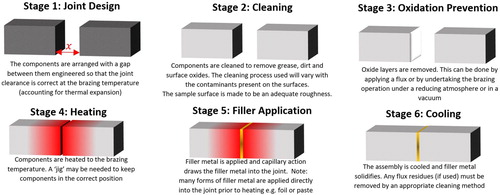
Table 3. A list of some major brazing techniques, the advantages and disadvantages of each, and their common applications.
Oxide removal
Oxide removal is an important part of the brazing process. This is often achieved with a flux; a mixture of complex chemical compounds that becomes molten during the brazing process and forms a layer over the joint, reacting with oxides and removing them from the bonding surfaces. Generally speaking, fluxes are not required in reducing atmosphere or vacuum brazing, but are needed for brazing in air. Brazing of certain materials, such as aluminium, can be undertaken in a vacuum in a manner described as ‘fluxless’, but this requires the presence of magnesium (either in the filler metal, in the base material or as elemental magnesium into the furnace) which acts as an oxygen getter and disrupts the aluminium oxide layer. Fluxes are not impermeable and thus do not prevent oxidation of the surface but will continue to react with and remove oxides formed by oxygen diffusion through the layer. Flux materials can have a wide array of properties, which require matching to the brazing operation.
The brazed joint
Joint factors affecting the brazing process
The strength and reliability of a brazed joint will be influenced by the cleanliness and surface roughness of the materials being joined, the gap between the joining parts and the filler metal selection.
Cleanliness of the joint
Surface contaminants, such as oil, grease, lubricants, dirt and oxide layers, inhibit wetting and capillary flow of the filler metal, and can prevent the flux from acting properly. While it is widely accepted in brazing that surface cleanliness is paramount in ensuring a high quality joint, there has been little systematic investigation of the effects. Bobzin et al. explored pre-cleaning and plasma cleaning of stainless steel and Inconel before brazing, and found that these treatments increased surface energy, and hence gave better wetting and improved joints [Citation17].
Surface roughness
The physical surface texture will affect brazing, and this is described by the lay of the surface (which influences the direction of flow of the filler metal [Citation18]), the waviness and the surface roughness. The latter, a measure of the small scale deviations of a material surface from flatness, is one of the most frequently characterised parameters in brazed joints.
Surface roughness is considered to have a critical impact on wettability and brazed joint quality, and has been investigated for a variety of base metals and molten fillers, with different findings on its influence and optimal characteristics. Most studies find that, at least to a point, smoother surfaces give better wetting and higher joint shear strength; evidence from Cu-9.7Sn-5.7Ni-7P on copper [Citation19] links lower roughness to reduced void volume, and increasing shear strength and surface energy have been found down to an average surface roughness (Ra) of 0.1 µm on copper [Citation20]. Work on brazing of ceramics (alumina, hafnium carbide and silica) by liquid copper, gallium and tin finds that roughening usually causes wettability to decrease [Citation21], and that contact angles between a molten Al drop and a TiN surface decrease with Ra, down to at least Ra = 0.3 µm [Citation22]. Similar results were also seen when roughening a Cu metallised Al2O3 surface, which reduces the wettability of Sn-Bi solders [Citation23].
There is evidence to the contrary however. Hong & Koo found an improved shear strength due to increased wetting with rough surfaces, up to a point where roughness is such that only asperity contacts are bonded, with an optimum Ra of 0.79 µm [Citation24]. From this Zaharinie et al. concluded an intermediate value (which they selected to be Ra = 0.2 µm) may be preferred [Citation19], as roughness increases the joining interface area and provides additional capillary paths for the flow of the brazing filler metal, up to a point where spreading of the filler metal is more difficult, with surface asperities impeding flow. Evidence has also been reported of there being only limited correlation between roughness and wetting, including for filler metals on aluminium nitride [Citation25], and in situations where wetting is dominated by chemical reactions [Citation26], though the range of surface conditions examined was limited.
Overall the sparse population of surface roughness studies (over a wide breadth of filler metal/parent metal combinations) make it hard to draw a clear conclusion on the influence of surface roughness on brazed joints. It is likely that the ideal roughness for each combination of filler metal and parent material will differ, and even within a single system, the range of roughness examined is frequently too low to pinpoint the ideal. From a practical point of view, a common handbook recommendation for surface roughness in brazing is 30–80 microinches RMS [Citation2], converted industrially to a range of Ra = 0.6–1.6 µm (consistent with most milled or machined finishes, [Citation27] ). Further investigation into the influence of surface roughness is needed before a well-supported conclusion on the optimal surface roughness generally for brazing can be made.
Figure 2. The average surface roughness caused by different manufacturing methods. Redrawn from [Citation28]. An acceptable surface finish for brazing is indicated by the red box [Citation27].
![Figure 2. The average surface roughness caused by different manufacturing methods. Redrawn from [Citation28]. An acceptable surface finish for brazing is indicated by the red box [Citation27].](/cms/asset/43ee1077-39cd-476d-93e1-0e4ca2d5f390/yimr_a_1613311_f0002_oc.jpg)
Joint clearance
Another factor affecting the strength of a brazed joint is the joint clearance (the gap between the two pieces of parent material to be joined). This is important in generating the capillary pressure which drives flow into the brazing gap. The pressure difference (Δp) due to capillary action can be found using the Young–Laplace equation:(1)
(1)
R is the radius of curvature of the meniscus and γ is the surface tension of the filler metal (constant for a particular filler metal and temperature, for example, for pure silver at its melting temperature, 1234 K,
is 0.914Nm−2) (see ).
Figure 3. Schematic illustrating the terms of importance in the Young–Laplace equation, which describes the pressure difference caused by capillary action, driving joint penetration by a molten filler metal during brazing.
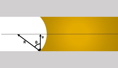
This radius is a function of the contact angle between the filler metal and the surface of the joint, θ, and the joint width, 2a:(2)
(2) As such the pressure difference (Δp) within the joint caused by capillary action can be expressed by
(3)
(3)
Thus, there is an inverse relationship between joint clearance and capillary pressure (), and it would be expected that the tightest joint clearance would give the best filling and the strongest brazed joint. However, the most widely known investigation into this effect, by Leach and Edelson at the Handy and Harman research laboratory in 1939, appears to suggest there is a limit to strength gains with narrower joints. Although the original report is no longer available, the data are commonly reproduced and discussed (e.g. [Citation1]) and can be seen, converted to SI units, in . These data (which correspond to 304 stainless steel butt joints using ISO 17672 Ag350 with a flux paste) indicate that there is an optimum brazed joint width (not the minimum achievable joint clearance), which will evidently vary with parent material and filler metal. It is interesting to note that the joint strength in all cases is significantly higher than the intrinsic strength of the ISO 17672 Ag350 filler metal (275 MPa) [Citation1].
Figure 4. Plot illustrating the trend in capillary pressure with gap width, calculated using the Young–Laplace equation, taking γ (pure silver at Tm) = 0.914Nm−2 and θ = 57°
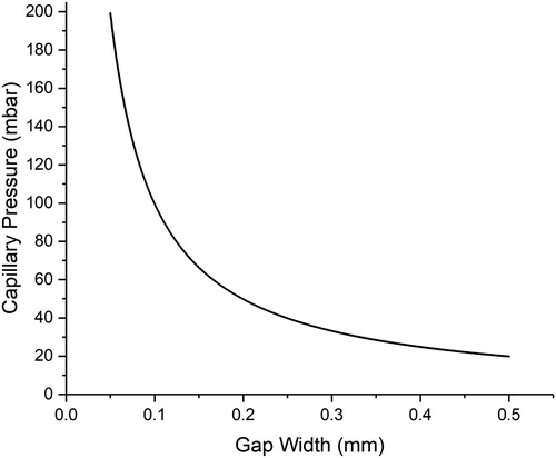
Figure 5. Graph depicting the strength of a brazed butt joint of 304 stainless steel joined with filler metal ISO 17672 Ag350 varying with joint clearance. Joint strength (black) redrawn from data from Leach and Edelson [Citation1]. Intrinsic strength of ISO 17672 Ag350 provided by [Citation1].
![Figure 5. Graph depicting the strength of a brazed butt joint of 304 stainless steel joined with filler metal ISO 17672 Ag350 varying with joint clearance. Joint strength (black) redrawn from data from Leach and Edelson [Citation1]. Intrinsic strength of ISO 17672 Ag350 provided by [Citation1].](/cms/asset/3fefd339-7672-40be-af1e-0b6ac4fb0951/yimr_a_1613311_f0005_oc.jpg)
Later work by Gray [Citation29] produced the data in , showing no strength decrease at joint clearances down to 1 µm. The disagreement between these two experiments likely occurs as the original work by Leach was carried out under flux in air, which inevitably leads to some flux inclusion and joint strength reduction, particularly for a narrow joint, whereas the succeeding work by Gray was performed under vacuum without flux.
Figure 6. Graph of work completed by Gray (replotted) showing tensile strength of samples brazed under reducing atmosphere (dissociated dry ammonia) in a furnace. This demonstrates that the drop off in strength seen in at tighter joint clearances is due to flux inclusions [Citation29].
![Figure 6. Graph of work completed by Gray (replotted) showing tensile strength of samples brazed under reducing atmosphere (dissociated dry ammonia) in a furnace. This demonstrates that the drop off in strength seen in Figure 5 at tighter joint clearances is due to flux inclusions [Citation29].](/cms/asset/448b6d7b-f290-4c0c-8581-4a30483c2cb3/yimr_a_1613311_f0006_oc.jpg)
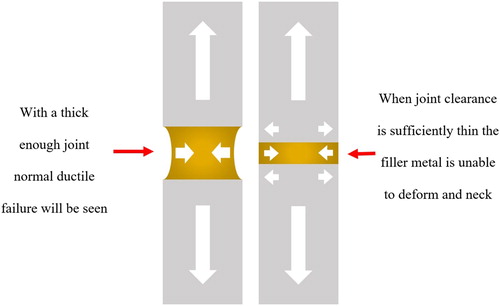
The increase in strength (above that of the filler metal alone) exhibited by brazed joints is due to the joint geometry preventing necking (). The small volume of filler metal is constrained by its metallurgical bond to the parent material, and experiences very high triaxial tension, thus supporting higher nominal loads than it would in bulk, and often failing (where failure is in the joint) with limited ductility.
Figure 7. Diagram illustrating the increase in joint strength seen when tighter joint clearances are used.
Joint characteristics
Mechanical property requirements
Defining the mechanical properties of a filler metal by standard test methods (such as tensile testing) is relatively simple, however, as for a well-designed joint the bulk properties of a filler metal often have little relationship to the physical properties of the joint it creates this is of limited practical use. Other factors, such as proper surface preparation and joint geometry are more in focus in engineering practice, and the mechanical properties of the filler metal are typically neglected. To take the example of a lap joint, if the joint overlap is designed to be 3–4 times the thickness of the thinnest joint member, the assembly would be expected to fail in the parent material and not in the joint itself. If it were desirable to quantify the shear performance of the filler by testing such a joint, then the standard requirements would apply and the joint overlap would have to be less than twice the thickness of the thinnest part of the sample.
Electrical properties
Sometimes brazed joints are used in functional applications where conductivity is required; although the majority of electronics applications make use of lower melting point solders, permitting higher application temperatures may be desirable to increase robustness. Increased joint area (typically to at least 1.5 times the thinnest joint member) may be used to avoid noticeable performance reduction.
The effect of the introduction of a joint on the performance of a conductor can be demonstrated by imagining a uniform cross section conductor of length L, containing a simple joint consisting of a layer of solder or braze of length x ( inset). When current flows through the conductor and joint in series, the total resistance of the assembly, RT, is the sum of the resistances of the conductor, RC, and the filler metal, RFM:(4)
(4) The resistance contribution arises due to the resistivity of the material and its length (as the cross section is the same for each), and so the percentage increase in resistance due to the presence of the joint (i.e. compared to the same length of material without a joint), RI, is given by:
(5)
(5)
Figure 8. Variation in resistance increase with relative joint size for a copper joined by ISO17672 Ag155 filler metal, BS EN ISO 9453:2014 Alloy number 711 solder and pure gold. Until the braze makes up a significant portion (>1%) of the joint length the resistance increase caused by the joint is low (<10% increase in resistance compared to pure copper).
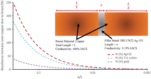
Equation (5) is plotted graphically in for different braze or solder materials joining copper.
From it is seen that when the solder or braze makes up less than 1% of the total conductor length under consideration (x/L < 0.01), the increase in resistance in the examples shown is less than 10%. It is not until the thickness of the joint reaches 10% of the total length that the resistance may be doubled over that of copper alone, though at this level a significant difference between regular filler metals and high conductivity gold is seen. Brazed joints are typically thin, and so for many conductive situations concerned with resistivity over a length greater than a few millimetres, the pressure to reduce the resistivity of these joint materials, compared to the improvement of other parameters such as cost and service temperature, is relatively low. In microelectronics the dimensions can be low however, and consideration of braze/solder conductivity may be important.
Interface types found in brazed joints
The formation of a brazed joint requires the filler to wet the parent material (see section ‘Wetting’) and an interaction between the parent material and components of the filler metal. A bond may be formed by partial dissolution of the parent metal in the filler (erosion of the parent metal can arise if this is too extensive), or diffusion of the filler into the parent material, leading to an interaction zone. Alternatively, (more prevalent in active brazing) there may be a reaction between the two, producing intermetallic compounds at the interface ().
Figure 9. Back Scattered Electron image of the interface between filler metal Ag-155 and high purity copper (left) and low carbon steel (right).
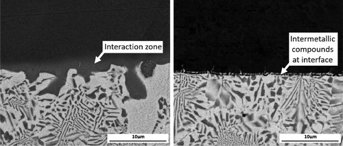
With the goal of understanding the principles behind bonding, recent research has focused on the interfacial interactions present in specific systems of current interest. For example, the joining of titanium (predominately Ti-6Al-4 V due to its aerospace applications) to aluminium (of various alloy specifications including 5A06 [Citation30], A6061-T6 [Citation31] and 5052 [Citation32]) is of interest in aviation for hybrid structures (for example, aluminium honeycomb joined to a titanium skin [Citation33]). Safe use of these hybrid structures demands extensive knowledge and control of the reactions that occur during joining [Citation34]. Takemoto & Okamoto [Citation35] found that the addition of silicon to Al based filler metals used to braze Al to Ti markedly reduced the interfacial zone width without significantly reducing the length of gap filled, up to 10at%Si where Ti7Al5Si12 formed at the interface. Chen et al. [Citation30] discovered that when an Al-12Si filler metal is used the silicon diffuses to the interface and forms intermetallic compounds; the composition and distribution of which vary with heat input.
The interface is of particular interest in dissimilar joints, and other systems receiving attention with regard to interfacial compounds formed in brazing include; SiC [Citation36–38], synthetic diamond [Citation39–41], and tungsten carbide [Citation42,Citation43]. Thus, while there is an abundance of research investigating an array of systems, filler metals and parent materials, there is a lack of a systematic study. This could yield underlying principles determining which combinations of base and filler metals are most likely to be compatible, and allow more informed filler metal selection and development of new filler metals tailored to specific applications.
Common brazing filler metals
Core brazing properties
The variety of alloy compositions that can be used as filler metals is vast, and the selection criteria by which the correct filler metal for the application is chosen will vary dramatically. Nevertheless, certain core behaviours common to all filler metals in any application can be identified; the melting range of the alloy, the wetting behaviour with the materials it is to join and the flow through the joint under brazing conditions. These key behaviours are expanded upon below.
Melting behaviour
A filler metal clearly must melt to operate. The melting behaviour is specified by the solidus and liquidus temperature, with the melting onset temperature (the solidus) and the melting range (the difference between the two points) being most significant for brazing.
The first of these is easy to specify; a filler metal must have a solidus temperature above the maximum temperature it will experience in service, but below the solidus of the lowest melting parent material. The second is more complex; some filler metals have a narrow melting range and some a wide one. Melting range is often linked to flow and this may drive selection (see section ‘Flow’), as may the required heating rate. Narrow melting range (a small temperature range between the solidus and liquidus) alloys can be used with fast or slow heating rates. Using a slow heating rate, such as in furnace brazing, for a filler metal with a wide melting range can result in extensive time where a solid and liquid phase are in equilibrium and coexist [Citation44]. This leads to liquation, where the liquid first formed (of a particular composition distinct from the bulk) flows into the joint gap, becoming physically separated from the solid residue. The resulting chemical inhomogeneity can be detrimental to the strength of the joint, and is often aesthetically displeasing.
Wetting
While not all brazing filler metals need to flow into a joint (where used as foils and pastes they may be pre-placed), wetting of the parent materials is essential. As described by Young’s well-known equation, wetting of a liquid droplet on a solid surface arises from the balance of three surface energy terms: γSL, the interfacial tension between solid surface and liquid, γSV, the surface free energy of the solid, and γLV, the surface tension of the liquid:in which θ is the contact angle between the solid and liquid, with wetting corresponding to θ<90°, and non-wetting to θ>90° [Citation45], ().
Figure 10. A non-wetting liquid with a contact angle (θ) of greater than 90° (left upper) and a wetting liquid with a contact angle of less than 90° (right upper). Redrawn from [Citation46]. An example of a non-wetting liquid within a brazed joint (left lower) and an example of a wetting liquid in a joint (right lower).
![Figure 10. A non-wetting liquid with a contact angle (θ) of greater than 90° (left upper) and a wetting liquid with a contact angle of less than 90° (right upper). Redrawn from [Citation46]. An example of a non-wetting liquid within a brazed joint (left lower) and an example of a wetting liquid in a joint (right lower).](/cms/asset/7adc8de9-b3f5-4fbe-bbf9-42ccd81b3bff/yimr_a_1613311_f0010_oc.jpg)
Many factors influence a filler wetting a base metal including surface roughness, surface cleanliness, presence of oxide layers, temperature, and brazing time [Citation47], which have been studied for various filler metal and surface combinations. In the case of wetting of stainless steel by a copper–silver eutectic, Ni and Sn additions to the eutectic did not produce measurable differences, but the Ti inclusions within the stainless steel being brazed led to wetting occurring at higher temperatures [Citation48]. Small alloying additions can drastically influence wetting characteristics, and titanium has been identified as effective in increasing wetting, demonstrated by the formation of a CuAg2.9at%Ti alloy in situ by placing a small quantity of Ti on top of a CuAg drop on a sapphire surface. A high contact angle was observed for a period of time before good wetting occurred, interpreted as being due to the delay in the Ti dissolving and diffusing to the metal/sapphire interface [Citation49]. Whilst most surface roughness studies utilise testing methods such as the well-known sessile drop test, other techniques exist to assess the influence of topography on wetting. Sekulic interpreted complex topography as a connected network of open microchannels and demonstrated that V-shaped capillary grooves allow liquid brazing filler metals (specifically Al-12Si on Al) to spread significantly more quickly than they would wet a flat substrate [Citation50].
Flow
In some brazing applications the filler metal may need to flow to enter the joint gap, but even when pre-placed, flow characteristics can still be important in making sure that all of the joint gap is filled. Better flowing alloys can penetrate smaller capillary gaps, but if an alloy is too free-flowing in larger gaps it may fail to be retained in the joint, leading to voids and lower strength. The flow of an alloy is primarily dictated by the relative amounts of solid and liquid present at the brazing temperature. If the alloy melts at a single point (e.g. a eutectic composition or a pure metal) then it will be fully liquid at the brazing temperature and will flow easily. An alloy brazed within its melting range will have some quantity of solid and liquid present; if it is largely molten it will flow well, if there is a significant solid fraction the flow will be more sluggish.
Filler metal families
Many different filler metals exist, and are frequently organised into families, (such as in ISO:1762:2016 [Citation13] where the classifications discussed below are established).
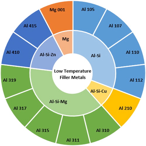
Low temperature brazing filler metals (class Al)
For low melting temperature materials (e.g. aluminium alloys), the fact that a filler metal must have a lower melting temperature than the materials it joins is a significant limitation. Most filler metals used for brazing aluminium are based on the aluminium-silicon system, with silicon supressing the liquidus temperature to 580–630°C ().
Figure 11. Sunburst chart displaying the low temperature filler metals (Class Al) defined in ISO:1762:2016 and the alloy systems they belong to.
In general, aluminium brazing requires more precise control than when brazing other materials. Even with silicon additions the gap between filler and parent metal melting point is low (on occasion as small as 10°C), leading to narrow process windows, and the stable Al2O3 oxide must be removed for successful brazing. Large scale industrial brazing of aluminium was not widely undertaken until 1980 when suitable temperature control was attained by furnace or chloride salt bath brazing, using fluxes with highly corrosive residues that required extensive post-brazing treatments [Citation1]. Vacuum brazing at that stage was too expensive for all but specialist aerospace applications, and although Al brazing in air is possible with some fluxes, these are corrosive (FL10) or require high temperatures, near the melting point of aluminium (FL20), to be activated [Citation51]. However, the increasing demand for air conditioning systems in modern cars required effective heat exchangers, whilst simultaneously the demand for weight reduction led to the replacement of brass and copper with aluminium in these structures. An improved method to braze aluminium was needed and this provided the impetus for the development of the NOCOLOK® (Solvay) brazing process. The flux used in this process is a mixture of fluoroaluminate salts which, once heated to its melting temperature (565–572°C, 5°C below the melting temperature of the standard filler Al-12wt-%Si), dissolves the aluminium oxide layer and prevents further oxidation [Citation52]. This flux requires a nitrogen atmosphere, but not a vacuum and leaves behind a non-corrosive residue. The development of this process, and the flux in particular, permitted aluminium brazing at suitable cost to enable commercialisation of aluminium heat exchangers.
In the fabrication of aluminium heat exchangers and radiators, the filler metal is metallurgically bonded to the aluminium sheet during manufacture, with one side (or both) covered with a layer of aluminium-silicon cladding. The aluminium sheet is then assembled into shape and placed in a furnace to melt the outer cladding layer and form the bond.
With aluminium and its alloys in widespread use, especially in the automotive and aerospace industries, development of aluminium-containing filler metals is ongoing. Many high strength aluminium alloys cannot use the Al-12Si eutectic alloy as the degree of alloying suppresses the parent metal solidus and the use of Al-12Si can cause property degradation and even localised melting [Citation53]. In an attempt to circumvent this, even lower melting point alloys found in the ternary Al-Cu-Si system have been investigated. Unfortunately, whilst copper supresses the melting temperature, it also enables CuAl2 intermetallic formation at the brazed interface, leading to embrittlement. Attempts to remedy this introduced Sn (and Mg as a wetting agent) to form an Al-7Si-20Cu-2Sn-1Mg alloy. A 6061 alloy brazed with this system showed a bonding strength of 196(±19) MPa, a significant improvement above a standard Al-12Si joint which could only demonstrate a 67(±7) MPa joint strength with the same 6061 alloy [Citation54]. Tsao et al. used this filler metal to bond 3003 aluminium alloys at a lower temperature (575°C) than a standard Al-12Si alloy and found the joint strength to exceed the UTS of the 3003 alloy [Citation55].
Further beneficial effects of Mg within the AlSi system include the creation of Mg2Si, with increased spreading (and thus enhanced wettability) correlating with increasing Mg2Si content [Citation56]. Researchers have also added rare earth elements to Al–Si alloys. Small quantities of erbium added into Al-20Cu-7Si filler metal for brazing a 3003 aluminium substrate improved both the wettability and hardness without significantly impacting the melting temperature [Citation53]. Lanthanum and cerium added to Al-12Si alloys showed an increase in wettability on LD2 and LD30 base alloys and a strength increase compared to AlSiMg alloys [Citation57].
Aluminium based filler metals can also join aluminium to titanium, which could lead to structures which are lightweight, have good corrosion resistance and low cost. Germanium and rare earth additions to the base Al-12Si system allowed successful furnace brazing of 6061 aluminium to Ti-6Al-4 V at 530°C [Citation58].
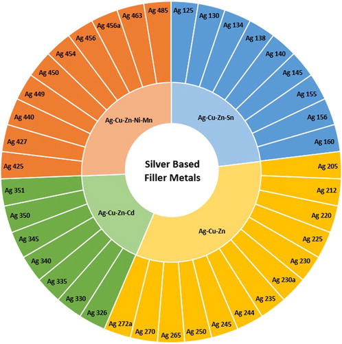
Silver-based alloys
Silver based alloys form a large segment of the market and are viewed as good general purpose filler metals which (depending on other alloy constituents) can wet most common engineering metals, including nickel, copper (and its alloys), low carbon and low alloy steels, stainless steel and tungsten carbide. The full range of ISO 17672:2016 [Citation13] silver based filler metals are shown in .
Figure 12. Sunburst chart displaying the silver based filler metals (Class Ag) defined in ISO:1762:2016 and the alloy systems they belong to.
An obvious drawback of such fillers is the cost, sensitive to the commodity price of silver due to their high silver content, and they thus tend to be used where other alternatives are not possible. Although copper–phosphorus alloys are often preferred when joining copper and its alloys (being used in around 60% of brazed joints on these materials [Citation2]) there are several situations in which they are unsuitable, including where there will be exposure to environmental sulphur [Citation59] or seawater (both of which will lead to rapid corrosion) or if the service temperature is too high (> 150°C). In these cases, silver based filler metals are preferred.
The major constituents of common silver bearing filler metals received attention as early as the 1940s in the case of the silver-zinc binary [Citation60] but the ternary Ag-Cu-Zn system on which most are now based was not evaluated until 1977 [Citation61] and received relatively little further attention, until recently. Interest was reignited when the health concerns of the then dominant cadmium-containing filler metals became known in the late 1970s, causing many companies to rapidly develop alternatives. Investigations conducted into various ternary and quaternary systems based on silver, copper and zinc, including: Ag-Cu-Zn-Ga [Citation62], Ag-Cu-Zn-Ni [Citation62], Ag-Cu-In [Citation63], Ag-Cu-Sn [Citation64] and Ag-Cu-Zn-Sn [Citation62] eventually led to tin being selected as a suitable replacement for cadmium [Citation65,Citation66], with many manufacturers adopting filler metals of the Ag-Cu-Zn-Sn quaternary system. Eventually, legislation introduced in the European Union (Commission regulation (EU) No 494/2011) banned the sale of brazing filler metals with cadmium concentrations ≥ 0.01wt-% (barring specialist military and aerospace applications) [Citation10]. The exact structure of phases, the microstructures and the thermal properties in the Ag-Cu-Zn system are still under investigation, with literature contributions being published as recently as 2018 [Citation67]. It is anticipated that investigations into this family of filler metals in service will continue; however, beyond the development of thrifted alloys with reduced silver, and hence cost (such as Bluebraze, Umicore; 20–35% Ag), composition innovations are improbable.
Copper–phosphorus and copper-based alloys (Class CuP and Class Cu)
Copper is a common component of many brazing filler metals ( and ); providing the ability to wet nickel and (to some degree) iron. Whilst these alloy systems still find widespread use, current development within this family is minimal.
Figure 13. Sunburst chart displaying the copper based filler metals (Class Cu) defined in ISO:1762:2016 and the alloy systems they belong to.
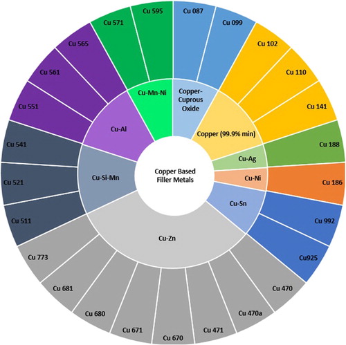
Figure 14. Sunburst chart displaying the copper–phosphorus-based filler metals (Class CuP) defined in ISO:1762:2016 and the alloy systems they belong to.
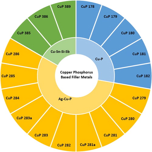
Copper–phosphorus alloys are comprised of a majority copper and 5–7.5wt-% phosphorus. Other minor additions include silver (up to 20wt-%) and tin (up to 7.5wt-%). The primary advantage of copper–phosphorus alloys over other filler metals is that when joining pure copper in air they do not require a flux, leading to time and cost benefits. The phosphorous reacts with atmospheric oxygen to form phosphorus pentoxide, which reacts with surface copper oxide forming a fusible slag, which also does not induce corrosion [Citation2].
There are significant drawbacks to this class however. The alloys tend to be brittle, limiting the forms they are available in (typically directly extruded rod), and the loads which can be safely experienced in service. Any copper alloy containing Ni or Fe (including all brasses) cannot be brazed with copper–phosphorous alloys as the nickel and iron phosphide phases formed are very brittle.
Current research and development on copper and copper–phosphorus-based filler metals is focussed on heat exchangers in the automotive industry [Citation68–71]. Up to the 1970s all vehicles used copper-based radiator systems, while, as noted in the section ‘Low temperature brazing filler metals (class Al)’, from this point increased interest in aluminium for this application was seen. To combat this, in the 1990s the International Copper Association developed copper-brass radiators (and the filler metals used with them). Earlier copper alloys lost their deformation-induced strength at temperatures associated with brazing and were designed to be soldered. When modern ‘anneal resistant’ copper with chromium precipitates was developed, a filler metal was needed for joining them at an appropriate temperature (590–650°C). This led to the development of OKC600 (Aurubis), a copper based filler metal with 4.2wt-% Ni, 15.6wt-% Sn, and 5.3wt-% phosphorus [Citation72]. It was the development of this filler metal (and the CuproBraze® (International Copper Association) process as a whole) that enabled copper-brass heat exchangers to compete with aluminium once again. Aluminium radiator systems have some drawbacks [Citation73], such as losing their strength when operating temperatures exceed 150°C, and in these instances copper alloys may be preferred [Citation68].
However, outside of this particular application current research on copper filler metals is concerned with the behaviour in service and understanding failures, rather than compositional refinement or property enhancement. Examples include investigations into the effects of multiple furnace exposures [Citation74], high cycle fatigue [Citation75] and shield gas influence [Citation76]. With development focussing on materials such as aluminium and nickel superalloys, as well as incorporating ceramics, it is looking less probable that copper based filler metals will be an area of substantial research in the near future.
High temperature brazing filler metals (class Ni, Class Pd and Class Au)
High temperature filler metals are frequently from one of three families, being predominantly based on nickel (class Ni), palladium (class Pd) or gold (class Au) (). No alloy listed in ISO:1762:2016 [Citation13] in any of these three filler metal families has a solidus temperature below 800°C, and as such they are used for brazing in applications where a high service temperature is required and high processing temperature can be tolerated, such as in jet engines and gas turbines. Pd and Au classes also find significant use in vacuum tube type devices and in metal-ceramic joining. Turbine blades in service experience exceedingly high temperatures and the filler metals used to repair them must have a high operating temperature.
Figure 15. Sunburst chart displaying the nickel, palladium and gold based filler metals (Class Ni, Class Au and Class Pd) defined in ISO:1762:2016 and the alloy systems they belong to.
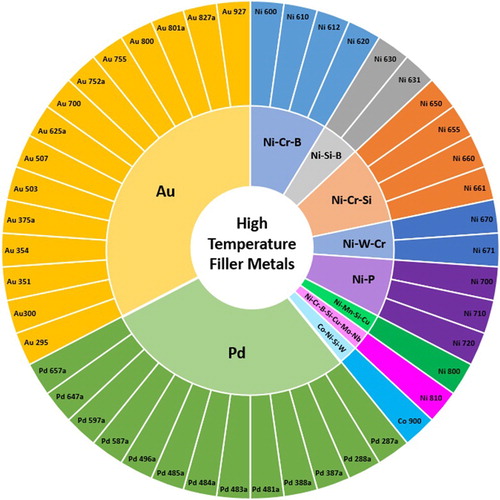
The high temperature brazing filler metals are largely one of two types of alloy:
Eutectic alloy systems (predominantly nickel or nickel-chromium based) with strong melting point depressants such as silicon, boron and phosphorus. They are used where high service temperatures are experienced and good corrosion resistance is necessary, such as in brazing of nickel and cobalt based superalloys and stainless steels.
Solid solution systems based on precious metals (palladium, gold and silver) with nickel and copper additions. They are often used on aerospace components in vacuum or inert gas furnace brazing, and possess good mechanical properties at elevated temperature and good oxidation resistance. The large working range of members of this family make them a good choice for step brazing procedures (where multiple brazed joints are needed but cannot be undertaken in a single operation, and multiple brazing steps are carried out at decreasing temperature, using a lower melting point filler metal each time) [Citation2].
The last 20 years has seen relatively few modifications to brazing filler metals for high temperature applications. Eutectic alloy compositions have seen development of the melting point suppressants with metalloids such as silicon and boron most commonly used, though investigations into phosphorus additions have been made [Citation77]. The incorporation of phosphorus allowed the development of the first iron-based amorphous brazing foil (VITROBRAZE® VZ2099 (Vacuumschmelze) [Citation77]). Other elements have also been investigated as additions including: zirconium and hafnium [Citation78] (which demonstrate homogeneity after brazing as well as desirable capillary characteristics); germanium [Citation79]; and beryllium [Citation6]. The principal advantage for phosphorus is its superior melting point suppression compared to silicon or boron. With increasing phosphorus content, it is possible to reduce the nickel content in favour of iron (reducing cost) without significant increase in the filler metal melting point [Citation77].
Common problems with brazed joint formation
Problems identified with brazed joints can be divided into issues which occur during joint formation (such as porosity, voids and the formation of deleterious intermetallic phases) and those which occur in service (such as corrosion).
Porosity and voids
In the region of the joint, brazing has many of the same characteristics as casting processes, and some similar defects to those encountered in casting may form. Unfilled space within the joint can be classified as either porosity (spherical in nature and resulting from gas entrapment in the molten filler, such as from hydrogen absorption and subsequent release on solidification, or the volatilisation of filler metal constituents) or voids (which can be any size and shape, caused by entrapped gas, flux residues or other contaminants).
Gas and flux filled voids are often more prevalent in slower flowing filler metals [Citation80] as flow of a filler metal through a joint helps to transport gas and molten flux (where used) to a free surface where it can escape. Filler metal flow through a joint can be encouraged by maintaining a temperature gradient across it, with molten filler metals flowing to the hottest point or area. Where critical (e.g. for leak tightness) void content can be assessed non-destructively by ultrasonic methods [Citation81].
Deleterious intermetallic phases
When brazing, a metallurgical bond is formed between filler metal and parent material, demanding an interaction between the two. However, this can lead to the formation of interfacial phases detrimental to the mechanical properties. A good example of this is in the joining of nickel superalloys with nickel-based filler metals containing metalloid elements (e.g. boron, silicon and phosphorus) which suppress the melting point of the filler metal down to 1000–1250°C, whilst simultaneously improving wetting and flow of the filler metal on the superalloy surface [Citation82]. Unfortunately, these melting point suppressants will form brittle intermetallic phases such as nickel borides and nickel silicides within the interface region of the joint which can lead to a reduction in strength and corrosion resistance [Citation82]. Research into alternative melting point suppressants such as hafnium attempts to address these issues; Ni-Hf-Cr filler metals were found to form no brittle phases during brazing and were rollable. Steel samples brazed with these alloys showed tensile strengths of 587 MPa, comparable to conventional Ni-based fillers (although due to the oxygen affinity of hafnium, a vacuum greater than 2×10⁻⁴ mbar was required) [Citation82]. The use of boron-containing nickel-based filler metals to join steels similarly results in deleterious intermetallic phases, but replacement with beryllium avoids phases which reduce joint strength [Citation6].
Repair of superalloy turbine blade components using filler metals with manganese additions as the melting point suppressant has been investigated [Citation83,Citation84]; the solubility of manganese within nickel allows for faster processing as the melting point suppressant does not have to be diffused away from the braze gap to allow solidification as a single phase, which must be done with boron, leading to longer processing times [Citation84]. Studies using germanium instead of manganese found similar results with single phase solidification giving joints with a UTS 90% of that of the parent material when tested at 980°C [Citation79].
Problems occurring in service
In service joints can experience problems due to mechanical loading and corrosion. While good joint design and brazing practice assist in alleviating such issues, these problems are extensive topics in their own right, and will be covered only in the respects that are specific to brazing here.
Mechanical loading
Failure due to mechanical loading is often due to poor joint design; for example, the occurrence of stress concentrations in certain areas (especially sharp corners) may cause local cracking. When designing brazed joints, it is imperative to evaluate where stresses will be experienced and design accordingly (see the section ‘Mechanical property requirements’).
Corrosion
Corrosion is an insidious problem in many materials, and can be particularly complex in brazed joints as they frequently involve different parent materials, a filler metal, and potentially interfacial phases. The presence of different materials in contact (and often in areas that are difficult to observe) provides an ideal environment for high corrosion rates in certain cases, which is often hard to detect. The combination of different materials also presents the risk of generating galvanic couples which could drive accelerated corrosion in aqueous environments; thus the joint assembly and operating environment need to be considered holistically to address corrosion issues, and testing of brazed joints is normally carried out on a case by case basis.
Interfacial corrosion is particularly problematic for stainless steels brazed with common silver-based filler metals (e.g. AgCuZnSn). Exposure to moisture in service dissolves the interfacial bonding layer and joint failure can occur after as little as three months’ immersion in water. A full account of these phenomena has been provided by Jarman [Citation85,Citation86]. This type of corrosion can be effectively prevented by using filler metals not containing zinc or cadmium [Citation1,Citation2].
Galvanic corrosion requires metallic contact between two metals of differing nobility, and an electrolytic connection between them; current will then flow between the two metals and through the electrolyte. The less noble metal becomes an anode and the more noble metal, a cathode, with increased corrosion being observed on the anodic material. It can occur between individual phases in an alloy; in multicomponent filler metal systems with multiple phases, or systems which produce multiple phases after interaction with the parent metal during brazing (microgalvanic corrosion) [Citation87–89].
Galvanic corrosion at a more macroscale also has particular relevance for brazing because the filler metal used is often based on a different metal than the parent material it is joining. The relative area of the cathode and anode can drastically alter behaviour; as it is current density that influences corrosion rates, if the anode is small and the cathode is large then the anode will corrode much more rapidly than if the electrodes were of similar sizes or the cathode was smaller. In brazed joints the braze is often substantially smaller than the parent and thus if the filler metal is less noble, rapid corrosion at the joint could occur. Galvanic corrosion is not restricted to any particular metals, and has been investigated in brazed joints including DHP (Deoxidised High Phosphorus) copper [Citation80], Zircaloy-4 [Citation87,Citation89], steel and titanium [Citation90,Citation91] and Ti-6Al-4V [Citation92].
Dezincification is a particular case of galvanic corrosion in which zinc rich phases are attacked. It occurs in brasses and in Ag-based filler metals which are exposed to seawater (particularly with limited aeration and stagnant water). The corrosion of the zinc-rich phase leaves behind a spongy silver/copper mass which has very poor mechanical properties and may easily fail. Higher silver content provides resistance to dezincification (43wt-% Ag for a ternary AgCuZn filer metal or 50wt-% Ag for a quaternary AgCuZnSn or AgCuZnCd) [Citation2], and it has been claimed that small additions of nickel (2–3wt-%) can enhance dezincification resistance [Citation2,Citation93].
Advanced brazing systems
The materials to be joined evidently have a large role in determining the joining method (for example, high Al/Ti superalloys are difficult to weld and so are brazed, albeit with a nickel plated layer to aid wetting), and also control the brazing filler metal to be used. However, with more advanced materials and more complex requirements for joining in advanced engineering, brazing systems beyond those in the classical groupings discussed in the section ‘Common brazing filler metals’ have been developed in recent years, with major families discussed here.
Active brazing alloys
One of the key features of brazing is its ability to bond a wide range of materials, including ceramics; oxides (e.g. alumina), nitrides (e.g. cubic boron nitride) and carbides (e.g. silicon carbide) in either ceramic-ceramic joining [Citation94–99] or metal-ceramic joining [Citation100–103]. Formerly ceramic brazing would have involved metalising the ceramic, allowing the filler metal to wet and bind to it; active metal brazing can avoid this. Active alloys contain chemically reactive elements, such as titanium, which promote wetting of the filler metal as it reacts with the ceramic. shows the reaction zone thickness with time for brazing Si3N4 at different temperatures with a titanium and non-titanium containing filler [Citation104]. The rate of reaction zone growth is clearly increased with titanium, indicating that the effect is not solely promotion of wetting, and the straight line fit in the root time plot indicates a diffusion mechanism behind the process.
Figure 16. The reaction zone thickness with time for brazing Si3N4 at different temperatures with a titanium and non-titanium containing filler (after [Citation45]).
![Figure 16. The reaction zone thickness with time for brazing Si3N4 at different temperatures with a titanium and non-titanium containing filler (after [Citation45]).](/cms/asset/994e91cc-714f-44ff-a287-c819cbb1095e/yimr_a_1613311_f0016_oc.jpg)
The amount of titanium that can be incorporated into active filler metals is limited by the increase in liquidus temperature tolerable and the risk of reaction with atmospheric oxygen. The chemical activity of the Ti addition can be increased by the inclusion of elements which have a low solubility for Ti, such as indium or tin [Citation105], or silver [Citation106,Citation107]. Alternatively, metallic Ti can be applied independently of the filler metal, as a tri-foil or cored wire, as powder in a polymeric binder [Citation108], or as TiH2, which breaks down to produce titanium at elevated temperature [Citation109,Citation110], forming an alloy in-situ.
Homogenous active metal brazing alloys were developed in the 1980s, and early developments are reviewed in [Citation45,Citation111]. The predominant systems are Cu–Ag alloys with an active element such as titanium [Citation112] zirconium [Citation96] or hafnium [Citation100]. Chromium is used as the active element in the brazing of diamond [Citation39,Citation113] and graphite [Citation114]. Other derivatives of copper systems e.g. Cu-Ti [Citation94] Cu-Pd-Ti [Citation97,Citation98] and Cu-Zn-Ti [Citation99] can also be used as active filler metals, and Cu-Ni-Mn-Nb [Citation101], Ti39.4Ni39.4Nb21.2 [Citation102], and Sn10Ag4Ti [Citation103] have all been investigated as active filler metals. A summary of some of the wide range of active alloys is given in . The sheer number of systems that have been investigated as filler metals for joining metals to ceramics, many as recently as the last 4 years, is a testament to the ongoing importance of this area in materials science [Citation95].
Table 4. Some of the active filler metals reported and used in metal-ceramic joints, with the elements identified as active shown in bold.
Brazing alloys designed to mitigate residual stress
When brazing dissimilar materials (be it metal–metal or metal-ceramic) differential thermal contraction on cooling from the brazing temperature will give rise to residual stresses in the joint [Citation129,Citation130]; indeed, residual stresses sufficient to cause failure can even be formed in joints between the same material just due to the Coefficient of Thermal Expansion (CTE) mismatch with the filler where a thick (∼10 μm) layer of intermetallic is formed [Citation131]. In the plane of the joint, the lower CTE material (usually the ceramic) is placed in compression and the higher CTE material (usually the metal) in tension (while the resulting Poission contraction means that stresses normal to the plane of the joint are compressive in the metal and tensile in the ceramic [Citation132]). Stresses are most intense at the interface, and diminish rapidly with distance away from it [Citation133]. The joint will be stress-free at the brazing temperature, with stresses developing on cooling [Citation130]; therefore, the capability of the filler to accommodate strain is key to the joint strength [Citation117,Citation134].
The residual stress distributions observed are frequently inhomogeneous [Citation130], and are greater in materials with higher yield stresses [Citation135], implying that residual stresses reach sufficiently high levels to cause plasticity. Indeed, good agreement between models and experiment cannot be obtained if only elastic deformation is considered [Citation129]. Stress levels vary greatly with the materials being brazed, the shape and size of the parent components and where in the joint is being examined, but reported values typically reach several hundred megaPascals.
Residual stresses in joints have been assessed by X-Ray Diffraction (XRD) [Citation136] and neutron diffraction [Citation132,Citation133,Citation137] (it is noteworthy that stresses within filler metal layers of normal thickness have not yet been resolved due to the size of sampling volume). For joints between plates which are sufficiently thin to bend under the residual stresses, the induced curvature can be used to gauge the stress level [Citation130], or, where the interface can be accessed, the difference in crack length generated by indentation in a stress free region and that in a region with residual stresses can be used as a measure [Citation138]. Particular materials may allow other techniques, such as peak shifts in Raman spectroscopy where diamond [Citation139,Citation140] or cubic boron nitride [Citation141] are involved in the joint. Stress values are also commonly accessed by Finite Element Modelling methods [Citation135,Citation141–143] (good agreement between such models and experiments have been found [Citation129,Citation134], though microstructure change-dependent effects are not always well captured [Citation144]).
It should be noted that residual stress is not always characterised directly, but inferred from properties such as the variation in shear strength of the joint [Citation145]. In the complex situation of a brazed joint between dissimilar materials it may not be possible to clearly ascribe differences in strength to residual stresses alone, especially as it has been shown that some brazing parameters can affect strength without significantly altering residual stresses [Citation139].
Composite fillers
The addition of other, chemically non-interacting, materials into the filler metal (sometimes confusingly described as fillers themselves) to form a composite filler has been used, initially to reduce cost [Citation146] but more recently to reduce residual stress [Citation147]. In general, the filler metal will have higher CTE than the ceramic, so the added materials are selected for low CTE (such as Si3N4 [Citation121], Al2O3 [Citation123,Citation148], TiN, [Citation122], BN [Citation126] or titanium compounds [Citation149]), and are dispersed in particulate form throughout the filler metal, reducing the overall CTE, and thus the residual stresses. Finite Element Modelling suggests that further reductions are possible with a non-uniform distribution of the added particles [Citation143]. Such additions can also cause strengthening, both as they tend to be high strength ceramic materials [Citation146], and as they act as nucleation sites and refine the microstructure in the joint [Citation149], though it has been reported, for the case of Ti-compounds, that they can reduce the effectiveness of the active metal [Citation149].
When adding particles to the filler metal, there can be difficulty in obtaining a uniform distribution [Citation121] and in finding appropriate particles with good wetting [Citation150]. For this reason, development of filler metals in which second phases are created in situ has occurred. For example, in joining Si3N4 an Ag–Cu filler metal with titanium additions and SiC particles was observed to form fine, homogenously distributed, Ti5Si3 particles [Citation151], and additions of boron to titanium bearing filler metals (e.g. Cu-Al-Ti with TiB2 [Citation150] or WB [Citation145]) can result in the formation of TiB whiskers [Citation152–154].
Ductile interlayers to relieve stress
Residual stresses in the joint may change the conclusion discussed earlier that thinner joints will have greater mechanical performance. Rather, a wider joint, with layers of different characteristics, may be able to accommodate differential strain with plasticity induced in ductile layers [Citation155] leading to there being an optimum joint thickness that is greater than the minimum achievable [Citation156].
A deliberate strategy that utilises this is the inclusion of an interlayer (interlayer brazing). This is often a ductile material that can undergo plastic deformation to accommodate some of the residual stress, though it can also incorporate a harder material to alter CTE [Citation157]. Ductile interlayers, such as copper, result in generally lower residual stresses than hard layers with low CTE, such as molybdenum [Citation158]. Note that, the interlayer is not the filler metal (the part that is responsible for bond formation), but a separate part of the braze material design and structure. Examples of interlayer materials effective at reducing residual stress include aluminium [Citation157], copper [Citation144,Citation159], ceramic-reinforced iron [Citation157] and tungsten [Citation144].
In some situations, thicker interlayers show reduced residual stresses ((a)), while interlayer CTE does not seem to have a great effect, the overall strain field being dominated by the two materials being joined [Citation137]. Models (neglecting the brazing layer) suggest that the CTE of the interlayer may have a more significant influence on the residual stresses if it is high [Citation160]. Analytical approximations to Finite Element models have been developed by Park et al. for the strain energy in the ceramic as a measure of the risk of fracture [Citation155]. The equations, used to generate (b) showing predicted ceramic strain energy for circular joints of increasing radius, for different interlayer materials, indicate that there is no sensitivity to the interlayer thickness, provided this is less than the joint width. The strongest sensitivity is to the joint area (cubic dependency) and the yield stress of the interlayer (squared dependency). It is noteworthy that the experiments showing an effect of interlayer thickness in (a) use niobium as an interlayer, which, with high yield stress, is predicted in (b) to permit higher stress levels to form.
Figure 17. (a) Neutron diffraction-determined residual stress levels for the ceramic in a MoSi-stainless steel joint with increasing interlayer thickness, replotted from [Citation137] and (b) the calculated strain energy (a measure of the fracture risk) following the analytical equations in Park et al. [Citation155], for different joint radii, r, in a joint between zirconia and Ni superalloy, using a series of different interlayer materials (Cu, Ni, Ti and Nb).
![Figure 17. (a) Neutron diffraction-determined residual stress levels for the ceramic in a MoSi-stainless steel joint with increasing interlayer thickness, replotted from [Citation137] and (b) the calculated strain energy (a measure of the fracture risk) following the analytical equations in Park et al. [Citation155], for different joint radii, r, in a joint between zirconia and Ni superalloy, using a series of different interlayer materials (Cu, Ni, Ti and Nb).](/cms/asset/761f1d04-0769-4bf8-85ae-f9bd0eca3bed/yimr_a_1613311_f0017_oc.jpg)
The idea of the interlayer as a phase within which deformation releases residual stresses suggests that promotion of yielding may be desirable. The yield strength of a material can be influenced by the incorporation of controlled porosity [Citation161]. This also provides gaps at the interface, allowing for further stress reduction (a square pattern cut into the interlayer by Electro Discharge Machining can result in joints of a higher strength than those without gaps, even though the bonding area is reduced [Citation162]).
Interlayers consisting of porous metals (woven wire mesh, foams or sponges) have been applied [Citation163]. For example, Ag-Cu-Ti fillers have been used for metal-ceramic joining with an interlayer of 0.2–0.6 mm 316 stainless steel foam (of unspecified porosity or pore dimensions) [Citation163], 0.2 mm thick nickel foam (of the electrodeposited type, with porosity >90% and pore diameter around 1 mm) [Citation142,Citation164], and with 3 mm of copper foam (porosity >96% and nominal pore size 0.6 mm) [Citation165] showing significant predicted residual stress reduction and experimental shear strength increase (in the case of the copper foam, a greater increase than when the same quantity of copper was included as a dense foil interlayer). Foams have even been further engineered for the purpose by inclusion of carbon nanotubes [Citation166] and it has also been claimed that some foam materials can react with active filler metal components and reduce the formation of undesirable brittle phases [Citation165,Citation166].
Alloys for small contact area joints
For many joining methods, thin sections, which easily melt or undergo shape change can pose challenges. Brazing does not suffer from this limitation, and is frequently used to connect faces to honeycomb cores in sandwich panels () (honeycomb foils can have thicknesses of ∼100 µm [Citation167]), and has been found to be effective for metallic foams [Citation168,Citation169]. In these investigations, it is frequently found that the brazed joint area, which is more massive than the thin honeycomb cores, is stronger than the core itself as the stresses developed in the joint are lower [Citation169–171]. Where foams are explored for heat exchange, brazing has been found to lead to the lowest thermal resistance of assessed bonding methods [Citation172]. Brazing is also used to bond metal foams as cores in sandwich panels [Citation173] and in making porous metals from woven wire, as reviewed in [Citation174].
Figure 18. A section of a nickel-based honeycomb sandwich. The face sheet of the honeycomb sandwich is marked I, the core is marked II and the brazing region is marked III [Citation167]. Reprinted from Materials Characterisation, 60, Qiuming Zhang & Xiaodong He, Microstructural Evolution and mechanical properties of a nickel-based honeycomb sandwich, 178–182., Copyright (2009), with permission from Elsevier.
![Figure 18. A section of a nickel-based honeycomb sandwich. The face sheet of the honeycomb sandwich is marked I, the core is marked II and the brazing region is marked III [Citation167]. Reprinted from Materials Characterisation, 60, Qiuming Zhang & Xiaodong He, Microstructural Evolution and mechanical properties of a nickel-based honeycomb sandwich, 178–182., Copyright (2009), with permission from Elsevier.](/cms/asset/7744a162-75e2-40f7-ba6a-49b1a720e535/yimr_a_1613311_f0018_ob.jpg)
Brazing of thin sections may be for high temperature use where adhesives will not serve and high strength and resistance to oxidation may be requirements. As well, erosion (dissolution of the parent metal to a high degree) must be considered. Brazed honeycomb sandwich panels may be encountered in thermal protection in reusable space launch vehicle designs, such as the NASA X-33 vehicle [Citation175], abradable seals in jet engines [Citation176] or in catalytic converters [Citation177]. Such situations normally see nickel superalloy face sheets and honeycomb cores, which can be brazed with conventional nickel alloys (e.g. ISO 17972-Ni620 [Citation167,Citation178,Citation179] or ISO 17972-Ni650 [Citation176]; ISO 17972-Ni620 can also join stainless steels [Citation180]). Mobile species in nickel brazing can however lead to problematic erosion (which is described in [Citation177]). Novel alloys developed in the Ni-Pd-Fe-Si system avoid boron and gain high temperature strength from the iron content [Citation181].
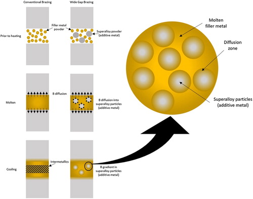
Wide gap brazing
In some instances, brazing is used in repair, rather than manufacture. Here, many of the aims are the same; to form a permanent, high strength joint between two materials, which can withstand service conditions. The difference is that the join is made along a failure (fracture or fatigue usually) and hence the conformation between the surfaces is not as exact as in engineered joints. This leads to the method being termed Wide Gap Brazing; joint thicknesses are greater than 0.127 mm [Citation182] (this latter reference provides an extensive review of the subject).
Wide Gap Brazing was invented by GE, and was originally applied to aviation vanes. The principle () is to combine powders of the filler metal (e.g. nickel-boron) and the additive metal (of similar composition to the metal being joined, usually a superalloy), possibly with a binder. The additive metal acts to 1) partially fill the void space; 2) provide an accessible sink for the melting point suppressants to diffuse into, 3) create narrow gaps within the joint, which are penetrated by the filler metal by capillary action and 4) permit alloy composition adjustment in the joint region [Citation183]. The brazing thermal treatment melts the filler metal which interacts with the joint surfaces and the additive metal powder, allowing the boron to diffuse away from the filler, and give a high temperature joint. It is important to note that the additive metal is not an inert component (a ‘filler’ in the filler metal), but its presence allows an intermetallic-free joint to be formed, with correspondingly better properties [Citation184]. Many other versions of the process have since been developed, using (largely proprietary) compositions of filler metal and superalloy. These are applied for repairs to turbine components, both in aviation and in power generation [Citation185].
Figure 19. Schematic of the wide gap brazing method.
It is important for strength, ductility [Citation186,Citation187], creep and fatigue performance [Citation185,Citation188] that there is sufficient time and temperature for the joint to form with little voiding and for dispersion of the melting point suppressant to avoid brittle intermetallics. On the other hand, as the melting point suppressant is taken up by the additive metal particles there is a risk they will melt. Should this happen, the re-solidification microstructure can form a hard eutectic, which displays poor fatigue life [Citation189]. Resistance to re-melting can be achieved by ensuring the additive particle size is not too small, and that brazing is carried out without additional superheat. The goal is that the solidification in the joint is isothermal, being brought about by the change of composition as the molten filler metal interacts with the solid additive metal [Citation182]. Very little interdiffusion takes place in the solid state, but it is rapid once liquid; use of a foil form of filler metal has been found to increase the densification and to result in reduced formation of intermetallic phases [Citation190].
Wide gap brazing has proved a useful repair strategy for a number of components in turbines; however, approaching the mechanical properties of new materials requires detailed process understanding and optimisation for each specific repair [Citation188]. This limits the method from use for certain critical parts, such as rotatives, and a better systematic understanding of how to achieve the best mechanical properties could widen the field of application.
The process can also be used where the usual small tolerances needed for brazing are not readily achievable, such as in the assembly of very large or difficult to machine components. In such a setting the process has also been used to bond dissimilar materials (nickel superalloy and stainless steel) [Citation191] ().
Figure 20. Wide gap brazed microstructure. Scanning Electron Micrographs of 304 stainless steel to X-750 Ni superalloy joints, braze at 1423 K, (a) using 4777 filler metal only, and (b) 4777 filler metal with 30vol% additive metal [Citation191]. Reprinted from Journal of Materials Processing Technology, 113, X.W Wu, R.S Chandel, H.P Seow, H Li, Wide Gap Brazing of stainless steel to nickel-based superalloy, 215–221., Copyright (2001), with permission from Elsevier.
![Figure 20. Wide gap brazed microstructure. Scanning Electron Micrographs of 304 stainless steel to X-750 Ni superalloy joints, braze at 1423 K, (a) using 4777 filler metal only, and (b) 4777 filler metal with 30vol% additive metal [Citation191]. Reprinted from Journal of Materials Processing Technology, 113, X.W Wu, R.S Chandel, H.P Seow, H Li, Wide Gap Brazing of stainless steel to nickel-based superalloy, 215–221., Copyright (2001), with permission from Elsevier.](/cms/asset/bd0bc1d3-9404-43e5-a671-96dd8d9d5005/yimr_a_1613311_f0020_ob.jpg)
With additive repair now being considered in aerospace to allow the repair of high value components [Citation192], wide gap brazing understanding could be applied in building up deposited repairs, which would be particularly appropriate for application in powder-based additive technologies.
Future challenges
For much of its history, brazing has needed to develop new filler metals, improving properties to meet various challenges, such as higher strength and operating temperature, and reducing the cost (notably in the filler metal families based on precious metals). However, the developments now required for brazing take filler metal development beyond a traditional metallurgical focus and will require the input of other research communities in uncovering new understanding and making the technological developments needed; this includes materials scientists working on ceramics and nanotechnology, those developing functional materials and devices, the users of advanced characterisation facilities and materials modellers. We present some of the most pressing challenges and significant opportunities below.
Key applications
Brazing will be a critical joining process for the implementation of many advanced technologies currently coming to the fore. Research is already underway in the field of joining nanoscale electronics (highly miniaturised electronic components utilising nanoparticles, nanowires and nanotubes [Citation193]), where it is the joining of nanoscale components (rather than the synthesis of the nanomaterials themselves) that is limiting development, with poor bonding between components or substrates leading to mechanical and electrical failures [Citation194]. Carbon nanotubes have been vacuum brazed using a commercially available Ti doped AgCu active brazing filler metal [Citation195] and silver nanowires joined using Au80Sn20 solder [Citation196]. Whilst nanowires can also be joined via direct fusion methods, joining of nanoparticles is harder as controlling the melting depth is challenging and particles tend to melt fully and coalesce. As nanoscale brazing or soldering does not require any melting of the nanoparticles, it offers a potential route to circumvent this issue [Citation197]. Nanobrazing can be performed on mixtures of nanoparticles using a laser of a specific wavelength such that the photon energy matches the absorption band of one type of particle, which is heated and melts, with the other nanoparticles remaining solid. This has been applied to Au and Pt [Citation198], and Ag and Pt [Citation197], but further research is required for wider exploitation. For widespread use of any nanojoining technique further understanding will be needed on the fundamental aspects of the process, such as the driving forces behind the joining mechanisms, the influence of surface topography, and the effect of crystal orientations, particularly for dissimilar material joining [Citation193]; an area in which brazing has always excelled.
Another prime area where brazing innovation is essential is in the joining of components within Solid Oxide Fuel Cells (SOFCs, devices which produce electricity from oxidising a fuel, with higher efficiency and reduced environmental impact than most other power generation methods [Citation199]). Within fuel cells each cathode-electrolyte-anode cell is joined to others to produce a ‘stack’ providing useable power output, and the joints must withstand high operating temperatures. Many different joining methods have been used but brazing, and in particular a recently developed technique known as reactive air brazing (RAB) [Citation200], is the most commonly used method [Citation201]. Reactive Air Brazing utilises a filler metal consisting of a noble metal (Ag) and a reactive metal (Cu). During brazing in air (which is required to prevent electrochemical degradation of the cathode materials which can occur under vacuum [Citation202]) the reactive metal oxidises, improving the wettability of the braze on the ceramic. Since emerging as a leading technique for joining SOFC fuel cell stacks, much development of RAB filler metals has ensued, including the incorporation of porous nickel interlayers to replace copper as the reactive metal [Citation199], and Al2TiO5 ceramic to adjust the thermal expansion coefficient [Citation203]. Density Functional Theory calculations have been used to suggest potential multi-cation oxides (such as CuAlO2, CuGaO2 and Cu3TiO4) which may be superior to CuO in the next generation of reactive air brazes. With the assistance of ab-inito modelling techniques, little-employed in filler metal development previously, these innovative new approaches in brazing will assist in reaching the prize of negligible emissions and high efficiency (45–60% [Citation204]) offered by SOFCs.
Increased operating temperature (retaining strength and corrosion resistance) is still a focus for development, but the authours would argue that there is a case for research on filler metals with lower melting temperatures as well. Extending the temperature envelope covered by brazing-like processes to temperatures below the traditional (but arbitrary) 450°C and closing the gap between many brazing filler metals and soft solders would meet a number of needs, including allowing for increased temperature margin of safety for electrical interconnects, brazing of highly alloyed high-strength aluminium grades (for example, the 7000 series) for aerospace heat exchangers and the bonding of functional materials, such as thermoelectrics or novel electrode materials in SOFCs, with sufficient capability for the required operating temperatures, but without a processing temperature where the properties of the material will be altered. Development of such filler metals will require understanding of systems containing the low melting point elements, which are currently little explored, and ways to control the microstructure to reduce the deleterious effect of the intermetallic phases which typically result from the use of significant amounts of melting point suppressants. Alternative approaches are possible, and nanoparticle additions have been used to lower process temperatures to <370°C in RAB filler metals [Citation205].
There is also a need for improvement in one of the most distinctive features of brazing, the ability to form thermally-stable joints between dissimilar materials. As designs are optimised for efficiency, it is increasingly common to want to use different materials for different parts of a component. Automotive lightweighting may favour the replacement of steel with aluminium, but this is not a wholesale substitution, and so joining steel to aluminium has become one of the most pressing of modern brazing challenges. Joint formation can be achieved, though it is still considered difficult [Citation206], due to the extremely low solid solubility of Fe in Al and the formation of hard, brittle intermetallic phases at the interface, which are highly detrimental to the mechanical strength of the joint [Citation207]. Modification of filler metals to reduce the size of the intermetallic layer has been attempted, including Si additions in Al for joining 5A05 aluminium alloy and AISI 321 stainless steel [Citation208]; Mg additions in Al for joining 5052 aluminium alloy and galvanised mild steel (unfortunately unsuccessful due to high hot cracking sensitivity caused by the Mg) [Citation207]; and Zr additions to Zn-15Al filler metals to join AA 6061 aluminium alloy to 304 stainless steel [Citation206]. Whilst some success has been noted (the Zr additions reduced the intermetallic layer thickness and increased shear strength by 10%) more progress is needed to produce interfaces which are sufficiently reliable, particularly after exposure to elevated temperatures for prolonged periods. Additionally, optimisation of heat input, to reduce the quantity of intermetallic compounds formed has been identified as a key area for future research to improve the joint strength between Al and Fe [Citation209]. Finally, although it is known that silicon in aluminium filler metals can control the growth of intermetallic layers by forming a ternary Fe-Al-Si phase ahead of the brittle Fe-Al binary, the specifics of how the intermetallic layer is formed is still not known and could benefit from systematic study [Citation209].
New directions for development and research
Brazing is a practical subject and has perhaps concentrated more on the what than the why; filler metals are developed for specific applications and assessed against the important criteria in each case, while fundamental understanding of the processes is less explored. As a result, the use of advanced characterisation techniques in the field has been less extensive than in other areas of modern materials research. One example of the power of X-ray Computed Tomography (XCT) to observe joint filling is shown in work from fusion engineering to bond a copper cooling pipe and a tungsten monoblock. The method was used find voids caused by a lack of wetting, and was capable of resolving defects as small as 10 μm in size [Citation210]. Other methods capable of assessing residual stresses on a finer scale and to greater precision would be of great use in engineering filler metals and brazed joints for bonding ceramics to metals for use in cutting tools for arduous environments.
It is likely that significant discoveries could be made by in operando observation of the brazing process, both to determine the flow of the filler metal (the XCT work above was post-braze only), and also to track the development of the phase structure (particularly intermetallics) within the joint region. Particularly challenging for characterisation would be the boron used as a melting point suppressant in nickel brazing alloys, but tracking how this constituent moves and the phases it exists in during brazing would be extremely valuable knowledge for process optimisation.
One area that has not been ignored in brazing is the potential for the discovery of new alloys motivated by the developments in High Entropy Alloys [Citation211]. While there is still some debate about their physical metallurgy [Citation212], one concept advanced is that where there are multiple elements present in high relative proportions (close to equiatomic) the high levels of entropy will favour solid solutions over intermetallic compounds. The formation of brittle intermetallics is a challenge in some areas of brazing, and the presence of multiple elements in the filler metal could facilitate bond formation between dissimilar materials. Some attempts have already been made in using HEA compositions as filler metals [Citation213,Citation214] and it is likely that there will be further developments in HEA compositions designed specifically for brazing [Citation215].
As a final example, it may be that as well as other communities contributing to advances in brazing, the knowledge from the field may be of benefit to other areas. Additive Manufacturing (AM) technology is developing rapidly, with attention now being paid to the design of specific alloys suited to the process. In doing this, researchers most often make comparison to welding [Citation216], with a need for material to undergo melting and solidification in contact with its own solid. But as AM becomes more complex, with developments into the use of AM for repair, and employing in-situ alloy formation, multiple materials or graded structures, some of the approaches from brazing may become valuable.
Summary
Brazing has been used in many engineering feats since it was first employed as a joining technique in antiquity. However, it is a testament to the versatility of the technology that it is still pivotal for some of the biggest engineering challenges facing mankind. Filler metals are adapted to particular joints, and advances in materials necessitate continuing development of filler metals. This progress will help push the boundaries in established technologies such as gas turbines and in the automotive industry and the development of new filler metals and processes will pave the way for leaps forward in clean energy generation (SOFCs and nuclear fusion) and in the rapidly progressing field of nanotechnology as development of nanoelectronics becomes the next challenge of the information age. It is the view of the authors that development of new filler metals and new brazing processes will be imperative across all these fields and more, and that despite being a technology 5000 years in development, brazing’s most advanced challenges are only just beginning to unfold.
Acknowledgements
The authors would like to acknowledge useful discussions with Phillip Webb of VBC Group, Dr Nicholas Ludford of TWI and Michael Clover and Dalton O’Brien of Johnson Matthey Metal Joining.
Disclosure statement
No potential conflict of interest was reported by the authors.
Additional information
Funding
Bibliography
- American Welding Society. Brazing handbook. 5th ed Miami (FL): American Welding Society; 2007.
- Roberts P. Industrial brazing practice. 2nd ed Boca Raton (FL): CRC Press; 2013.
- Guo W, Wang T, Lin T, et al. Bismuth borate zinc glass braze for bonding sapphire in air. Mater Charact. 2018;137:67–76.
- Kim J, Lee T. Brazing method to join a novel Cu54Ni6Zr22Ti18 bulk metallic glass to carbon steel. Sci Technol Weld Join. 2017;22:714–718.
- Jin W, He Y, Yang J, et al. Novel joining of dissimilar materials in the graphite/Hastelloy N alloy system using pure Au doped with Si particles. Mater Charact. 2017;131:388–398.
- Ivannikov AA, Kalin BA, Sevryukov ON, et al. Study of the Ni–Si–Be system as a base to create boron-free brazing filler metals. Sci Technol Weld Join. 2018;23:187–197.
- Bo C, Wen-Jiang Z, Wen-Wen L, et al. Joining of SiO2f/SiO2 composite to Ti-6Al-4 V using Ag-Cu-In-Ti brazing fillers, the joint strengths, and microstructures. Weld World. 2017;61:833–837.
- de Prado J, Sánchez M, Utrilla MV, et al. Study of a novel brazing process for W-W joints in fusion applications. Mater Des. 2016;112:117–123.
- Davis JR. ASM Specialty handbook: copper and copper alloys. Materials Park (OH): ASM International; 2001; 305.
- European Commission. Commission regulation (EU) No 494/2011. Off J Eur Union. 2011;54:2–5.
- Okulov IV, Pauly S, Kühn U, et al. Effect of microstructure on the mechanical properties of as-cast Ti-Nb-Al-Cu-Ni alloys for biomedical application. Mater Sci Eng C. 2013;33:4795–4801.
- Burghardt I, Lüthen F, Prinz C, et al. A dual function of copper in designing regenerative implants. Biomaterials. 2015;44:36–44.
- ISO/TC 44. Brazing — filler metals (ISO 17672:2016) [Internet]. 3rd ed British Standards Institution; 2016; Available from: https://www.iso.org/obp/ui/#iso:std:iso:3677:ed-3:v1:en
- Shapiro AE. Brazing of conventional titanium alloys. ASM Handbook, New Ed. 2016;6:36–43.
- Specification for filler metals AWS A5.8M/A5.M-2011.
- Batista RI. Brazing of refractory and reactive metals. ASM Handbook, Vol 6 Welding, Brazing, Solder. 1993;6:941–947.
- Bobzin K, Öte M, Wiesner S. Investigation of the effect of contaminations and cleaning processes on the surface properties of brazing surfaces. IOP Conf Ser Mater Sci Eng. 2017;181:012027.
- Zhao H, Elbel S, Hrnjak P. Influence of surface morphology on wetting behaviors of liquid metal during aluminum heat exchanger fabrication. Proceedings of the 15th International Refrigeration and Air Conditioning Conference; 2014 July 14–17; Purdue, IN: p. 1–8.
- Zaharinie T, Huda Z, Izuan MF, et al. Development of optimum process parameters and a study of the effects of surface roughness on brazing of copper. Appl Surf Sci. 2015;331:127–131.
- Elsawy AH, Fahmy MF. Brazing of Si3N4 ceramic to copper. J Mater Process Technol. 1998;77:266–272.
- Hitchcock SJ, Carroll NT, Nicholas MG. Some effects of substrate roughness on wettability. J Mater Sci. 1981;16:714–732.
- Sobczak N, Pietrzak K. Effect of substrate preparation on wetting in Al-TiN system. Proceedings of the 3rd international conference on high temperature capillarity; 2000 Nov 19–22; Kurashiki, Japan; 2001 p. 173–178.
- Chen YY, Duh JG, Chiou BS. Effect of substrate surface roughness on the wettability of Sn-Bi solders. J Mater Sci Mater Electron. 2000;11:279–283.
- Hong IT, Koo CH. The study of vacuum-furnace brazing of C103 and Ti-6Al-4 V using Ti-15Cu-15Ni foil. Mater Chem Phys. 2005;94:131–140.
- Taranets NY, Jones H. The influence of surface roughness and pre-oxidation state on the wettability of aluminium nitride by commercial brazes. J Mater Sci. 2004;39:5727–5734.
- Li Y, Liu W, Sekulic DP, et al. Reactive wetting of AgCuTi filler metal on the TiAl-based alloy substrate. Appl Surf Sci. 2012;259:343–348.
- Schwartz MM. Brazing. 2nd ed. Materials Park (OH): ASM International; 2003.
- Oberg E, Jones FD, Horton HL, et al. Machinery’s handbook 26: A reference Book for the mechanical Engineer, Designer, manufacturing Engineer, Draftsman, Toolmaker, and Machinist. 26th ed. New York City (NY): Industrial Press; 2000.
- Gray TH. No Title. Pittsburgh (Pa): Westinghouse Research Labs.
- Chen S, Li L, Chen Y, et al. Si diffusion behavior during laser welding-brazing of Al alloy and Ti alloy with Al-12Si filler wire. Trans Nonferrous Met Soc China (English Ed). 2010;20:64–70.
- Cao R, Sun JH, Chen JH. Mechanisms of joining aluminium A6061-T6 and titanium Ti–6Al–4 V alloys by cold metal transfer technology. Sci Technol Weld Join. 2013;18:425–433.
- Chen WB. Microstructure and mechanical properties of tungsten inert gas welded–brazed Al/Ti joints. Sci Technol Weld Join. 2016;21:547–554.
- Zhu Z, Lee KY, Wang X. Ultrasonic welding of dissimilar metals, AA6061 and Ti6Al4 V. Int J Adv Manuf Technol 2012;59:569–574.
- Winiowski A, Majewski D. Braze welding TIG of titanium and aluminium alloy type Al - Mg. Arch Metall Mater. 2016;61:133–142.
- Takemoto T, Okamoto I. Intermetallic compounds formed during brazing of titanium with aluminium filler metals. J Mater Sci. 1988;23:1301–1308.
- Zhong Z, Hou G, Zhu Z, et al. Microstructure and mechanical strength of SiC joints brazed with Cr3C2 particulate reinforced Ag-Cu-Ti brazing alloy. Ceram Int. 2018;44:11862–11868.
- Valenza F, Gambaro S, Muolo ML, et al. Wetting of SiC by Al-Ti alloys and joining by in-situ formation of interfacial Ti3Si(Al)C2. J Eur Ceram Soc. 2018;38:3727–3734.
- Tian WB, Sun ZM, Zhang P, et al. Brazing of silicon carbide ceramics with Ni-Si-Ti powder mixtures. J Aust Ceram Soc. 2017;53:511–516.
- Chen J, Mu D, Liao X, et al. Interfacial microstructure and mechanical properties of synthetic diamond brazed by Ni-Cr-P filler alloy. Int J Refract Met Hard Mater. 2018;74:52–60.
- Mukhopadhyay P, Raghava Simhan D, Ghosh A. Challenges in brazing large synthetic diamond grit by Ni-based filler alloy. J Mater Process Technol. 2017;250:390–400.
- Mukhopadhyay P, Ghosh A. On bond wear, grit-alloy interfacial chemistry and joint strength of synthetic diamond brazed with Ni-Cr-B-Si-Fe and Ti activated Ag-Cu filler alloys. Int J Refract Met Hard Mater. 2018;72:236–243.
- Zhang X, Liu G, Tao J, et al. Brazing of WC-8Co cemented carbide to steel using Cu-Ni-Al alloys as filler metal: microstructures and joint mechanical behavior. J Mater Sci Technol. 2018;34:1180–1188.
- Amirnasiri A, Parvin N, Haghshenas MS. Dissimilar diffusion brazing of WC-Co to AISI 4145 steel using RBCuZn-D interlayer. J Manuf Process. 2017;28:82–93.
- Arenas MF, Acoff VL, Reddy RG. Physical properties of selected brazing filler metals. Sci Technol Weld Join. 2004;9:423–429.
- Akselsen OM. Advances in brazing of ceramics. J Mater Sci. 1992;27:1989–2000.
- Eustathopoulos N, Voytovych R. The role of reactivity in wetting by liquid metals: a review. J Mater Sci. 2016;51:425–437.
- Kogi S, Kajiura T, Hanada Y, et al. Wetting and spreading behavior of molten brazing filler metallic alloys on metallic substrate. International Symposium on Interfacial Joining and Surface Technology. 2014;61:012017–(6 pages).
- Kozlova O, Voytovych R, Devismes MF, et al. Wetting and brazing of stainless steels by copper-silver eutectic. Mater Sci Eng A. 2008;495:96–101.
- Voytovych R, Robaut F, Eustathopoulos N. The relation between wetting and interfacial chemistry in the CuAgTi/alumina system. Acta Mater. 2006;54:2205–2214.
- Sekulic DP. Wetting and spreading of liquid metals through open microgrooves and surface alterations. Heat Transf Eng. 2011;32:648–657.
- BS EN 1045:1997. Brazing. Fluxes for brazing. Classification and technical delivery conditions. British Standards Institution; 1997. Available from: https://bsol.bsigroup.com/Bibliographic/BibliographicInfoData/000000000001153747
- Markovits T, Takács J, Lovas A, et al. Laser brazing of aluminium. J Mater Process Technol. 2003:143–144:651–655.
- Shi YW, Yu Y, Xia ZD, et al. Study on Al-Cu-Si braze containing small amount of rare earth erbium. Front Mater Sci China 2008;2:351–356.
- Chuang TH, Tsao LC, Tsai TC, et al. Development of a low-melting-point filler metal for brazing aluminum alloys. Metall Mater Trans. 2000;31:2239–2245.
- Tsao LC, Weng WP, Cheng MD, et al. Brazeability of a 3003 alloy with Al-Si-Cu-based aluminum filler metals. J Mater Eng Perform. 2002;11:360–364.
- Yang T, Zhang D, Wang K, et al. Aluminium-silicon-magnesium filler metal for aluminium vacuum brazing wettability and characteristics of brazing microstructure. Mater Trans. 2016;57:983–987.
- Wang S, Zhou H, Kang Y. The influence of rare earth elements on microstructures and properties of 6061 aluminum alloy vacuum-brazed joints. J Alloys Compd. 2003;352:79–83.
- Chang SY, Tsao LC, Lei YH, et al. Brazing of 6061 aluminum alloy/Ti-6Al-4 V using Al-Si-Cu-Ge filler metals. J Mater Process Technol. 2012;212:8–14.
- Brown L. Copper Development Association, Cost-Effective Manufacturing: Joining of Copper and Copper Alloys. Report; CDA Publication No. 98. 1994.
- Andrews KW, Davies HE, Hume-Rothery W, et al. The equilibrium diagram of the system silver-Zinc. Proc R Soc A Math Phys Eng Sci. 1941;177:149–167.
- Chang YA, Goldberg D, Neumann JP. Phase diagrams and thermodynamic properties of ternary copper-silver systems. J Phys Chem Ref Data. 1977;6:621–674.
- Zhongmin L, Songbai X, Xianpeng H, et al. Study on microstructure and property of brazed joint of AgCuZn-X(Ga, Sn, In, Ni) brazing alloy. Rare Met Mater Eng. 2010;39:397–400.
- Sisamouth L, Hamdi M, Ariga T. Investigation of gap filling ability of Ag-Cu-In brazing filler metals. J Alloys Compd. 2010;504:325–329.
- Basri DK, Sisamouth L, Farazila Y, et al. Brazeability and mechanical properties of Ag–Cu–Sn brazing filler metals on copper-brazed joint. Mater Res Innov. 2014;18:S6-429–S6-432.
- Wierzbicki J, Malec W, Stobrawa J, et al. Studies into new, environmentally friendly Ag-Cu-Zn-Sn brazing alloys of low silver content. Arch Metall Mater. 2011;56:147–158.
- Watanabe T, Yanagisawa A, Sasaki T. Development of Ag based brazing filler metal with low melting point. Sci Technol Weld Join. 2011;16:502–508.
- Dimitrijević SP, Manasijević D, Kamberović Ž, et al. Experimental investigation of microstructure and phase transitions in Ag-Cu-Zn brazing alloys. J Mater Eng Perform. 2018;27:1570–1579.
- Hasap A, Noraphaiphipaksa N, Kanchanomai C. Torsional strength and failure of copper alloy brazing joint. Eng Fail Anal. 2015;48:174–184.
- Tapper L, Ainali M. Interactions between the materials in the tube-fin-joints in brazed copper-brass heat exchangers. Proc. 2001 Veh. Therm. Manag. Syst. Conf. Nashville, Tenessee; 2001. p. p-363.
- Cotton N. Back to the future with copper brazing. Mach Des. 2008;80:50–55.
- Shabtay YL, Ainali M, Lea A. New brazing processes using anneal-resistant copper and brass alloys. Mater Des. 2004;25:83–89.
- Rissanen PT. inventor; Outokumpu Oy, assignee. Copper alloys to be used as brazing filler metals. United States Patent; US 5,378,294 1995 Jan 3.
- Scheel J, Gustafsson B. Cuprobraze mobile heat exchanger technology. Outokumpu Copper Strip AB, Sweden. SAE Technical paper series. 2000.
- Cortese ME, Neill RFO. A study of the effect of multiple braze furnace exposures on 304L stainless steel copper-brazed assemblies. Dana Corporation. SAE technical paper series. 2004.
- Basak S, Pal TK, Shome M. High-cycle fatigue behavior of MIG brazed galvanized DP600 steel sheet joint—effect of process parameters. Int J Adv Manuf Technol. 2016;82:1197–1211.
- Quintino L, Pimenta G, Iordachescu D, et al. MIG brazing of galvanized thin sheet joints for automotive industry. Mater Manuf Process. 2006;21:63–73.
- Hartmann T, Vacuumschmelze DN. New amorphous brazing foils for exhaust gas applications. Proceedings of the 4th International Brazing and Soldering Conference 2009 April 26-29; Orlando, Florida, USA. 2009; p. 110–117.
- Khorunov K, Maksymova S, Samokhin S, et al. Brazing filler metals containing Zr and Hf as depressants. Trans JWRI. 2001;30:419–424.
- Dinkel MK, Heinz P, Pyczak F, et al. New boron and silicon free single crystal-diffusion brazing alloys. Proceedings of the International Symposium on Superalloys (2008). 2008;211–220.
- Aminazad AM, Hadian AM, Ghasimakbari F. Investigation on corrosion behaviour of copper brazed joints. Procedia Mater Sci. 2015;11:672–678.
- Tillmann W, Sievers N, Pfeiffer J, et al. Examination of the porosity in reactive Air brazed joints by ultrasonic testing. Adv Eng Mater. 2014;16:1437–1441.
- Lugscheider BE, Humm S. High-Temperature brazing of superalloys and stainless steels with novel ductile Ni-Hf-based filler metals. Adv Mater. 2002;4:138–142.
- Piegert S, Laux B, Rösier J. Design of a braze alloy for fast epitaxial brazing of superalloys. IOP Conf Ser Mater Sci Eng. 2012;33:012028.
- Laux B, Piegert S, Rösler J. Braze alloy development for fast epitaxial high-temperature brazing of single-crystalline nickel-based superalloys. Metall Mater Trans A Phys Metall Mater Sci. 2009;40:138–149.
- Jarman RA, Myles JW, Booker CJL. Interfacial corrosion of brazed stainless steel joints in domestic tap water. Br Corros J. 1973;8:33–37.
- Jarman RA, Linekar GAB, Booker CJL. Interfacial corrosion of brazed stainless steel joints in domestic tap water. II Metallographic Aspects Br Corros J. 1975;10:150–154.
- Kim KH, Lee JG, Lee GJ, et al. Compositional effects of Zr-rich multi-component brazing alloys on the corrosion of Zr alloy joints. Corros Sci. 2014;88:328–336.
- Kvryan A, Livingston K, Efaw C, et al. Microgalvanic corrosion behavior of Cu-Ag active braze alloys investigated with SKPFM. Metals (Basel). 2016;6:91.
- Lee JG, Lee GJ, Park JJ, et al. Corrosion behavior in high-temperature pressurized water of Zircaloy-4 joints brazed with Zr-Cu-based amorphous filler alloys. J Nucl Mater. 2017;488:204–209.
- Lee MK, Park JJ, Lee GJ, et al. Corrosion of Ti-STS dissimilar joints brazed by a Ag interlayer and Ag-Cu-(Pd) alloy fillers. J Nucl Mater. 2011;409:183–187.
- Lee MK, Park JJ, Lee JG, et al. Phase-dependent corrosion of titanium-to-stainless steel joints brazed by Ag-Cu eutectic alloy filler and Ag interlayer. J Nucl Mater. 2013;439:168–173.
- Lee MK, Lee JG. Mechanical and corrosion properties of Ti–6Al–4V alloy joints brazed with a low-melting-point 62.7Zr–11.0Ti–13.2Cu–9.8Ni–3.3Be amorphous filler metal. Mater Charact. 2013;81:19–27.
- Takemoto T, Okamoto I. Effect of composition on the corrosion behavior of stainless steels brazed with silver-base filler metals. Welding Journal. 1984;63:300–307.
- Nishino T, Urai S, Okamoto I, et al. Ti3SiC a phase in SiC / SiC joint brazed with Cu4T57 alloy. J Mater Sci Lett. 1990;9:1417–1418.
- Xiong H, Chen B, Zhao H, et al. V-containing-active high-temperature brazes for ceramic joining. Weld World. 2016;60:99–108.
- Vianco PT, Walker CA, Smet DD, et al. Understanding the run-out behavior of a Ag-Cu-Zr braze alloy when used to join alumina to an Fe-Ni-Co alloy. Weld J. 2016;95:36–42.
- Liu CF, Zhang J, Zhou Y, et al. Effect of holding time on the self-joining of silicon nitride. J Alloys Compd. 2009;471:217–221.
- Liu CF, Zhang J, Meng QC, et al. Joining of silicon nitride with a Cu76.5Pd8.5Ti15 filler alloy. Ceram Int. 2007;33:427–431.
- Zhang J, Liu CF, Naka M, et al. A TEM analysis of the Si3N4 / Si3N4 joint brazed with a Cu-Zn-Ti filler metal. J Mater Sci. 2004;39:4587–4591.
- Lugscheider E, Tillmann W. Development of new active filler metals in a Ag-Cu-Hf system. Weld J Res Suppl. 1990;69:416–421.
- Li J, Sheng G, Huang L. Additional active metal Nb in Cu-Ni system filler metal for brazing of TiC cermet/steel. Mater Lett. 2015;156:10–13.
- Liu YZ, Zhang LX, Liu CB, et al. Brazing C/SiC composites and Nb with TiNiNb active filler metal. Sci Technol Weld Join. 2011;16:193–198.
- Chang SY, Hung YT, Chuang TH. Joining alumina to Inconel 600 and UMCo-50 superalloys using an Sn10Ag4Ti active filler metal. J Mater Eng Perform. 2003;12:123–127.
- Nakao Y, Nishimoto K, Saida K. Bonding of Si3N4 to metals with active filler metals. Trans Japan Weld Soc. 1989;20:66–76.
- Nicholas MG, Valentine TM, Waite MJ. The wetting of alumina by copper alloyed with titanium and other elements. J Mater Sci. 1980;15:2197–2206.
- Tillmann W, Lugscheider E, Xu R, et al. Kinetic and microstructural aspects of the reaction layer at ceramic/metal braze joints. J Mater Sci. 1996;31:445–452.
- Wang H, Cao J, Feng J. Brazing mechanism and infiltration strengthening of CC composites to TiAl alloys joint. Scr Mater. 2010;63:859–862.
- Kozlova O, Braccini M, Voytovych R, et al. Brazing copper to alumina using reactive CuAgTi alloys. Acta Mater. 2010;58:1252–1260.
- Liu GW, Qiao GJ, Wang HJ, et al. Pressureless brazing of zirconia to stainless steel with Ag-Cu filler metal and TiH2 powder. J Eur Ceram Soc. 2008;28:2701–2708.
- He P, Liu D, Shang E, et al. Effect of mechanical milling on Ni-TiH2 powder alloy filler metal for brazing TiAl intermetallic alloy: the microstructure and joint’s properties. Mater Charact. 2009;60:30–35.
- Elssner G, Petzow G. Metal_ceramic joining. Isij Int. 1990;30:1011–1032.
- Wang N, Wang DP, Yang ZW, et al. Interfacial microstructure and mechanical properties of zirconia ceramic and niobium joints vacuum brazed with two Ag-based active filler metals. Ceram Int. 2016;42:12815–12824.
- Chattopadhyay AK, Chollet L, Hintermann HE. Experimental investigation on induction brazing of diamond with Ni-Cr hardfacing alloy under argon atmosphere. J Mater Sci. 1991;26:5093–5100.
- Zhang J, Wang T, Liu C, et al. Effect of brazing temperature on microstructure and mechanical properties of graphite/copper joints. Mater Sci Eng A. 2014;594:26–31.
- Fan D, Huang J, Wang Y, et al. Active brazing of carbon fiber reinforced SiC composite and 304 stainless steel with Ti-Zr-Be. Mater Sci Eng A. 2014;617:66–72.
- Liu XP, Zhang LX, Sun Z, et al. Microstructure and mechanical properties of transparent alumina and TiAl alloy joints brazed using Ag-Cu-Ti filler metal. Vacuum. 2018;151:80–89.
- Laik A, Mishra P, Bhanumurthy K, et al. Microstructural evolution during reactive brazing of alumina to Inconel 600 using Ag-based alloy. Acta Mater. 2013;61:126–138.
- Kuzumaki T, Ariga T, Miyamoto Y. Effect of additional elements in Ag-Cu based filler metal on brazing of aluminum nitride to metals. ISIJ Int. 1990;30:1135–1141.
- Shi JM, Zhang LX, Pan XY, et al. Microstructure evolution and mechanical property of ZrC-SiC/Ti6Al4 V joints brazed using Ti-15Cu-15Ni filler. J Eur Ceram Soc. 2018;38:1237–1245.
- He Y, Zhang J, Lv P, et al. Characterization of the Si3N4/42CrMo joints vacuum brazed with Pd modified filler alloy for high temperature application. Vacuum. 2014;109:86–93.
- Zhao YX, Wang MR, Cao J, et al. Brazing TC4 alloy to Si3N4 ceramic using nano-Si3N4 reinforced AgCu composite filler. Mater Des. 2015;76:40–46.
- Wang T, Liu C, Leinenbach C, et al. Microstructure and strengthening mechanism of Si3N4/invar joint brazed with TiNp-doped filler. Mater Sci Eng A. 2016;650:469–477.
- Zhou YH, Liu D, Niu HW, et al. Vacuum brazing of C/C composite to TC4 alloy using nano-Al2O3strengthened AgCuTi composite filler. Mater Des. 2016;93:347–356.
- Wang Z, Wang G, Li M, et al. Three-dimensional graphene-reinforced Cu foam interlayer for brazing C/C composites and Nb. Carbon N Y. 2017;118:723–730.
- Zhang ZY, Xiao B, Duan DZ, et al. Investigation on the brazing mechanism and machining performance of diamond wire saw based on Cu-Sn-Ti alloy. Int J Refract Met Hard Mater. 2017;66:211–219.
- Yang ZW, Zhang LX, Ren W, et al. Interfacial microstructure and strengthening mechanism of BN-doped metal brazed Ti/SiO2-BN joints. J Eur Ceram Soc. 2013;33:759–768.
- Sciti D, Bellosi A, Esposito L. Bonding of zirconia to super alloy with the active brazing technique. J Eur Ceram Soc. 2001;21:45–52.
- Liu HB, Zhang LX, Wu LZ, et al. Vacuum brazing of SiO2glass ceramic and Ti-6Al-4 V alloy using AgCuTi filler foil. Mater Sci Eng A. 2008;498:321–326.
- Levy A. Thermal residual stresses in ceramic-to-metal brazed joints. J Am Ceram Soc. 1991;74:2141–2147.
- Bing K, Eigenmann B, Scholtes B, et al. Brazing residual stresses in components of different metallic materials. Mater Sci Eng A. 1994;174:95–101.
- Lee HT, Chen MH, Jao HM, et al. Influence of interfacial intermetallic compound on fracture behavior of solder joints. Mater Sci Eng A. 2003;358:134–141.
- Vila M, Prieto C, Zahr J, et al. Residual stresses in ceramic-to-metal joints: diffraction measurements and finite element method analysis. Philos Mag. 2007;87:5551–5563.
- Wang X-L, Hubbard CR, Spooner S, et al. Mapping of the residual stress distribution in a brazed zirconia-iron joint. Mater Sci Eng A. 1996;211:45–53.
- Galli M, Botsis J, Janczak-Rusch J, et al. Characterization of the residual stresses and strength of ceramic-metal braze joints. J Eng Mater Technol. 2009;131:021004.
- Jiang W, Gong J, Tu S, et al. A comparison of brazed residual stress in plate-fin structure made of different stainless steel. Mater Des. 2009;30:23–27.
- Iancu OT, Munz D, Eigenmann B, et al. Residual stress state of brazed ceramic/metal compounds, determined by analytical methods and X-ray residual stress measurements. J Am Ceram Soc. 1990;73:1144–1149.
- Vaidya RU, Rangaswamy P, Bourke MAM, et al. Measurement of bulk residual stresses in molybdenum disilicide / stainless steel joints using neutron diffraction. Acta Metall. 1998;46:2047–2061.
- Grunder T, Piquerez A, Bach M, et al. Residual stress in brazing of submicron Al2O3 to WC-Co. J Mater Eng Perform. 2016;25:2914–2921.
- Buhl S, Leinenbach C, Spolenak R, et al. Influence of the brazing parameters on microstructure, residual stresses and shear strength of diamond-metal joints. J Mater Sci. 2010;45:4358–4368.
- Buhl S, Leinenbach C, Spolenak R, et al. Microstructure, residual stresses and shear strength of diamond-steel-joints brazed with a Cu-Sn-based active filler alloy. Int J Refract Met Hard Mater. 2012;30:16–24.
- Zhu Y, Ding W, Xu J, et al. An investigation of residual stresses in brazed cubic boron nitride abrasive grains by finite element modelling and Raman spectroscopy. Mater Des. 2015;87:342–351.
- Sun R, Zhu Y, Guo W, et al. Microstructural evolution and thermal stress relaxation of Al2O3/1Cr18Ni9Ti brazed joints with nickel foam. Vacuum. 2018;148:18–26.
- Galli M, Botsis J, Janczak-Rusch J. Relief of the residual stresses in ceramic-metal joints by a layered braze structure. Adv Eng Mater. 2006;8:197–201.
- Martens L, Tillmann W, Lugscheider E, et al. Strength and microstructure of brazed cemented carbide and silicon nitride joints. J Mater Process Technol. 1996;58:13–23.
- Dai X, Cao J, Wang Z, et al. Brazing ZrO2 ceramic and TC4 alloy by novel WB reinforced Ag-Cu composite filler: microstructure and properties. Ceram Int. 2017;43:15296–15305.
- Coad BC. inventor; GTE products corporation, assignee. Brazing compositions United States patent US4409181A. 1983 Oct 11.
- Zhu M, Chung DDL. Improving the strength of brazed joints to alumina by adding carbon fibres. J Mater Sci. 1997;32:5321–5333.
- Si X, Cao J, Song X, et al. Reactive air brazing of YSZ ceramic with novel Al2O3 nanoparticles reinforced Ag-CuO-Al2O3composite filler: microstructure and joint properties. Mater Des. 2017;114:176–184.
- Miao Q, Ding W, Zhu Y, et al. Brazing of CBN grains with Ag-Cu-Ti/TiX composite filler – the effect of TiX particles on microstructure and strength of bonding layer. Mater Des. 2016;98:243–253.
- Yang M, Lin T, He P, et al. Brazing of Al2O3 to Ti-6Al-4 V alloy with in situ synthesized TiB-whisker-reinforced active brazing alloy. Ceram Int. 2011;37:3029–3035.
- Zhang J, He YM, Sun Y, et al. Microstructure evolution of Si3N4/Si3N4 joint brazed with Ag-Cu-Ti+SiCp composite filler. Ceram Int. 2010;36:1397–1404.
- Yang M, Lin T, He P, et al. In situ synthesis of TiB whisker reinforcements in the joints of Al2O3/TC4 during brazing. Mater Sci Eng A. 2011;528:3520–3525.
- Yang M, Lin T, He P. Microstructure evolution of Al2O3/Al2O3 joint brazed with Ag-Cu-Ti+B+TiH2 composite filler. Ceram Int. 2012;38:289–294.
- Niu GB, Wang DP, Yang ZW, et al. Microstructure and mechanical properties of Al2O3/TiAl joints brazed with B powders reinforced Ag-Cu-Ti based composite fillers. Ceram Int. 2017;43:439–450.
- Park J-W, Mendez PF, Eagar TW. Strain energy distribution in concentric ceramic-to-metal joints. Acta Mater. 2002;50:883–899.
- Kar A, Ghosh M, Ray AK, et al. Effect of interfacial thickness and residual stress on the mechanical property of the alumina-stainless steel braze joint interface. Mater Sci Eng A. 2008;498:283–288.
- Suganuma K. Recent advances in joining technology of ceramics to metals. ISIJ Int. 1990;30:1046–1058.
- Zhou Y, Bao FH, Ren JL, et al. Interlayer selection and thermal stresses in brazed Si3N4-steel joint. Mater Sci Technol. 1991;7:863–868.
- Qu D, Zhou Z, Yum Y, et al. Mechanical characterization and modeling of brazed tungsten and Cu-Cr-Zr alloy using stress relief interlayers. J Nucl Mater. 2014;455:130–133.
- Park JW, Mendez PF, Eagar TW. Strain energy release in ceramic-to-metal joints by ductile metal interlayers. Scr Mater. 2005;53:857–861.
- Goodall R, Mortensen A. Physical metallurgy. 5th ed. Laughlin D, Hono K, editors. Amsterdam, The Netherlands: Elsevier; 2014.
- Park JW, Eagar TW. Strain energy release in ceramic-to-metal joints with patterned interlayers. Scr Mater. 2004;50:555–559.
- Shirzadi AA, Zhu Y, Bhadeshia HKDH. Joining ceramics to metals using metallic foam. Mater Sci Eng A. 2008;496:501–506.
- Zhu Y, Qi D, Guo W, et al. The braze joint between Al2O3 to 1Cr18Ni9Ti using a nickel foam. Weld World. 2015;59:491–496.
- Lin JH, Luo DL, Chen SL, et al. Control interfacial microstructure and improve mechanical properties of TC4-SiO2f/SiO2joint by AgCuTi with Cu foam as interlayer. Ceram Int. 2016;42:16619–16625.
- Ba J, Lin J, Wang H, et al. Carbon nanotubes-reinforced Ni foam interlayer for brazing SiO2-BN with Ti6Al4 V alloy using TiZrNiCu brazing alloy. Ceram Int. 2018;44:3684–3691.
- Zhang Q, He X. Microstructural evolution and mechanical properties of a nickel-based honeycomb sandwich. Mater Charact. 2009;60:178–182.
- Longerich S, Piontek D, Ohse P, et al. Joining strategies for open porous metallic foams on iron and nickel base materials. Adv Eng Mater. 2007;9:670–678.
- Jarvis T, Voice W, Goodall R. The bonding of nickel foam to Ti-6Al-4 V using Ti-Cu-Ni braze alloy. Mater Sci Eng A. 2011;528:2592–2601.
- Nowacki J, Moraniec K. Evaluation of methods of soldering AlSi and AlSi-SiC particle composite Al foams. J Mater Eng Perform. 2015;24:426–433.
- Shirzadi AA, Kocak M, Wallach ER. Joining stainless steel metal foams. Sci Technol Weld Join. 2004;9:277–279.
- De Jaeger P, T’Joen C, Huisseune H, et al. Assessing the influence of four bonding methods on the thermal contact resistance of open-cell aluminum foam. Int J Heat Mass Transf. 2012;55:6200–6210.
- Song YF, Xiao LR, Zhao XJ, et al. Fabrication, microstructure and shear properties of Al foam sandwich. Mater Manuf Process. 2016;31:1046–1051.
- Kang KJ. Wire-woven cellular metals: the present and future. Prog Mater Sci. 2015;69:213–307.
- Blosser ML. Development of metallic thermal protection systems for the reusable launch vehicle. Langley Research Center, Hampton, Virginia. Space technology and applications international forum (STAIF - 97) 1997.
- Potter DJ, Chai YW, Tatlock GJ. Improvements in honeycomb abradable seals. Mater High Temp. 2009;26:127–135.
- Bode H, Gao W. Oxidation behaviour and phase stability at and above 700°C in brazed areas of metal-supported automotive converters with honeycomb structures made of ultra-thin FeCrAIRE materials for diesel applications. Mater High Temp. 2005;22:367–374.
- Zhang QM, He XD. Microstructure evolution and mechanical properties of nickel based honeycomb sandwich. Mats Sci Tech. 2009;25:1432–1436.
- Zhang Q, He X, Li Y. Microstructure evolution and mechanical properties of a nickel-based honeycomb sandwich aged at 900°C. Mater Sci Eng A. 2011;530:202–207.
- Mehrizi S, Hadian AM, Hadian A, et al. Interfacial phenomena in brazing of a stainless steel face sheet to a honeycomb core. Adv Mater Res. 2009;83-86:1236–1242.
- Rabinkin A. Melting characteristics, glass-forming ability and stability of Ni-Pd-Si and Ni-Pd-TM-Si alloys in the concentration range 10–22 at. % Si. Mater Sci Eng A. 1990;124:251–258.
- Huang X, Miglietti W. Wide gap braze repair of gas turbine blades and vanes—a review. J Eng Gas Turbines Power. 2012;134:010801–(17 pages).
- McGuire D, Huang X, Nagy D, et al. Effect of tungsten addition on the nucleation of borides in wide gap brazed joint. J Eng Gas Turbines Power. 2010;132:062101.
- Zhang J, Zhang Z, Sun J, et al. Effect of gap filler on microstructure of wide gap brazing seam. Mater Trans. 2000;41:1073–1076.
- Miglietti W, Du Toit M. High strength, ductile braze repairs for stationary gas turbine components—part I. J Eng Gas Turbines Power. 2010;132:082102–(12 pages).
- Lim LC, Lee WY, Lai MO. Nickel base wide gap brazing with preplacement technique part 1 – effect of material and process parameters on formation of macrovoids. Mater Sci Technol. 1995;11:1041–1045.
- Henhoeffer T, Huang X, Yand S, et al. Microstructure and high temperature tensile properties of wide gap brazed cobalt based superalloy X-40. Mater Sci Technol. 2010;26:431–439.
- Miglietti W, Du Toit M. High strength, ductile braze repairs for stationary gas turbine components—part II. J Eng Gas Turbines Power. 2010;132:082103–(10 pages).
- Osoba LO, Ojo OA. Influence of solid-state diffusion during equilibration on microstructure and fatigue life of superalloy wide-gap brazements. Metall Mater Trans A. 2013;44:4020–4024.
- Corbin SF, Murray DC, Bouthillier A. Analysis of diffusional solidification in a wide-gap brazing powder mixture using differential scanning calorimetry. Metall Mater Trans A. 2016;47:6339–6352.
- Wu XW, Chandel RS, Seow HP, et al. Wide gap brazing of stainless steel to nickel-based superalloy. J Mater Process Technol. 2001;113:215–221.
- Matthews N. Aircraft Sustainment and repair. 1st ed. Jones R, Baker A, Matthews N, et al., editors. Oxford, UK: Butterworth-Heinemann; 2018.
- Zhou Y, Hu A. From microjoining to nanojoining. Open Surf Sci J 2010;3:32–41.
- Cui Q, Gao F, Mukherjee S, et al. Joining and Interconnect formation of nanowires and carbon nanotubes for nanoelectronics and nanosystems. Small. 2009;5:1246–1257.
- Wu W, Hu A, Li X, et al. Vacuum brazing of carbon nanotube bundles. Mater Lett. 2008;62:4486–4488.
- Li Q, Chen Z, Zhang X, et al. Au80Sn20 based targeted noncontact nanosoldering with low power consumption. Opt Lett. 2018;43:4989–4992.
- Liu L, Huang H, Hu A, et al. Nano brazing of Pt-Ag nanoparticles under femtosecond laser irradiation. Nano-Micro Lett. 2013;5:88–92.
- Mafuné F, Kohno Jy, Takeda Y, et al. Nanoscale soldering of metal nanoparticles for construction of higher-order structures. J Am Chem Soc. 2003;125:1686–1687.
- Zhou Q, Bieler TR, Nicholas JD. Transient porous nickel interlayers for improved silver-based solid oxide fuel cell brazes. Acta Mater. 2018;148:156–162.
- Kim JY, Hardy JS, Weil KS. Novel metal-ceramic joining for planar SOFCs. J Electrochem Soc. 2005;152:J52.
- Chao CL, Chu CL, Fuh YK, et al. Interfacial characterization of nickel-yttria-stabilized zirconia cermet anode/interconnect joints with Ag-Pd-Ga active filler for use in solid-oxide fuel cells. Int J Hydrogen Energy. 2015;40:1523–1533.
- Phongpreecha T, Nicholas JD, Bieler TR, et al. Computational design of metal oxides to enhance the wetting and adhesion of silver-based brazes on yttria-stabilized-zirconia. Acta Mater. 2018;152:229–238.
- Kiebach R, Engelbrecht K, Grahl-Madsen L, et al. An Ag based brazing system with a tunable thermal expansion for the use as sealant for solid oxide cells. J Power Sources. 2016;315:339–350.
- Stambouli AB, Traversa E. Solid oxide fuel cells (SOFCs): a review of an environmentally clean and efficient source of energy. Renew Sustain Energy Rev. 2002;6:433–455.
- Gorji AH, Simchi A, Kokabi AH. Development of composite silver/nickel nanopastes for low temperature joining of yttria-stabilized zirconia to stainless steels. Ceram Int. 2015;41:1815–1822.
- Yang J, Xue S, Sekulic DP. An impact of zirconium doping of Zn-Al braze on the aluminum-stainless steel joint. J Mater Eng Perform. 2017;26:358–365.
- Su Y, Hua X, Wu Y. Influence of alloy elements on microstructure and mechanical property of aluminum-steel lap joint made by gas metal arc welding. J Mater Process Technol. 2014;214:750–755.
- Song JL, Lin SB, Yang CL, et al. Effects of Si additions on intermetallic compound layer of aluminum-steel TIG welding-brazing joint. J Alloys Compd. 2009;488:217–222.
- Singh J, Arora KS, Shukla DK. Dissimilar MIG-CMT weld-brazing of aluminium to steel: a review. J Alloys Compd. 2019;783:753–764.
- Barrett TR, Evans LM, Fursdon M, et al. Virtual engineering of a fusion reactor: application to divertor design, manufacture, and testing. IEEE Trans Plasma Sci. 2019;47:889–896.
- Zhang Y, Zuo TT, Tang Z, et al. Microstructures and properties of high-entropy alloys. Prog Mater Sci. 2014;61:1–93.
- Pickering EJ, Jones NG. High-entropy alloys: a critical assessment of their founding principles and future prospects. Int Mater Rev. 2016;61:183–202.
- Bridges D, Zhang S, Lang S, et al. Laser brazing of a nickel-based superalloy using a Ni-Mn-Fe-Co-Cu high entropy alloy filler metal. Mater Lett. 2018;215:11–14.
- Tillmann W, Wojarski L, Manka M, et al. Eutectic high entropy alloys – A novel class of materials for brazing applications. Proceedings from the International Brazing & Soldering Conference. 2018. P. 142–148.
- Snell R. The development of novel silver brazing alloys [dissertation]. University Of Sheffield; 2018.
- Thomas M, Baxter GJ, Todd I. Normalised model-based processing diagrams for additive layer manufacture of engineering alloys. Acta Mater. 2016;108:26–35.