
 ?Mathematical formulae have been encoded as MathML and are displayed in this HTML version using MathJax in order to improve their display. Uncheck the box to turn MathJax off. This feature requires Javascript. Click on a formula to zoom.
ABSTRACT
Research on powder-based additive manufacturing of aluminium alloys is rapidly increasing, and recent breakthroughs in printing of defect-free parts promise substantial movement beyond traditional Al–Si–Mg) systems. One potential technological advantage of aluminium additive manufacturing, however, has received little attention: the design of alloys for use at T > ~200°C, or ~1/2 of the absolute melting temperature of aluminium. Besides offering lightweighting and improved energy efficiency through replacement of ferrous, titanium, and nickel-based alloys at 200–450°C, development of such alloys will reduce economic roadblocks for widespread implementation of aluminium additive manufacturing. We herein review the existing additive manufacturing literature for three categories of potential high-temperature alloys, discuss strategies for optimizing microstructures for elevated-temperature performance, and highlight gaps in current research. Although extensive microstructural characterisation has been performed on these alloys, we conclude that evaluations of their high-temperature mechanical properties and corrosion responses are severely deficient.
Introduction
Existing AM studies on Al alloys
Research on aluminium (Al) alloys has become firmly established in the field of additive manufacturing (AM). Within the past five years, the number of publications focused on laser powder bed fusion (LPBF) of Al alloys has increased from ∼50 to ∼250 publications per year, behind only steels and Ti alloys [Citation1]. This trend is not surprising given the critical industrial role that Al alloys play as high-strength, lightweight structural materials. AM provides a further benefit with its ability to produce complex component shapes with enhanced weight savings and functionally graded components. By taking a subset of 100 of the most cited publications in the field, Kusoglu et al. [Citation1] determined that the majority of studies on LPBF of Al, ∼65%, have been limited to near-eutectic Al–Si–(Mg) alloys due to their favourable processability and weldability. This is expected because the Al–Si–(Mg) alloys possess small freezing ranges, thereby minimising their hot cracking tendency [Citation2]. Recent advances in AM processability have led to an additional ∼30% of studies devoted to variants of commercial wrought alloys, such as Al–Cu–(Mg) and Al–Mg. The latter alloys were previously plagued by extensive hot cracking issues in AM due to their large solidification range. Several strategies recently developed to combat this issue include the introduction of solutes that reduce the freezing range of the alloys, such as Si [Citation3–5], substrate/powder bed preheating [Citation6], mixing of elemental powders [Citation7], or promoting the formation of an equiaxed grain structure through chemical modification [Citation8,Citation9].
Existing reviews of AM for Al [Citation10–18] are largely focused on processing/property relationships in Al–Si–(Mg) alloys. Processing conditions during AM are notoriously complex and resulting materials properties can be significantly affected by changes in beam/powder interactions, preferential evaporation of elements, scan strategy, scan speed, laser power, powder layer thickness, spot size, powder size/morphology, substrate temperature, processing atmosphere, and even the make and model of the AM equipment. The effects of these factors are often determined using parametric studies, with subsequent examinations of the resulting microstructures and mechanical properties. The management of residual stresses and reduction of microstructural defects deleterious to mechanical performance is also critical. Defects include porosity (gas and lack-of-fusion), thermal cracking, and hot tearing/cracking. Although the results of parametric studies are understood qualitatively and used to build defect-free parts, a major challenge remaining is understanding the physical processes that occur during beam/powder/melt pool interactions and the role of thermal history during processing (also termed intrinsic or in-situ heat treatment in some studies) as components are built layer-by-layer [Citation19]. The application of a volumetric energy density model is often used to correlate microstructural features to thermal history, but the model is too simplistic to capture the complex physical processes occurring during AM processing [Citation10].
Philosophy of review
Although there is a large body of literature on AM for Al, much of that work is technology focused, i.e. focused on the production of complex, defect-free components with comparable or superior properties to conventionally manufactured components. While process optimisation is important – especially for Al alloys where the process window is small or non-existent – the exclusion of alloy design from AM research represents a significant missed opportunity: the ability to design entirely new alloys with properties not achievable using conventional processing. For Al, this opportunity manifests in the ability to design alloys for high-temperature use.
It is well-known that commercial cast and wrought Al alloys cannot be used for structural applications in the 200–450°C temperature range as their strengthening precipitates coarsen and dissolve, creating a technological gap for lightweight alloys that is currently filled by ferrous, Ti, and Ni-base alloys. shows that as the strength of conventional 7xxx and 2xxx Al alloys decreases with temperature, an opportunity space opens between the Al alloys and Ti–6Al–4V at T > 200°C [Citation20]. The prevalent AM Al–Si–(Mg) alloys and AM versions of wrought alloys also suffer from a decrease in strength with temperature. The potential high-temperature alloys which fill the opportunity space should be characterised by high specific strength and stiffness relative to conventional alloys at T > ∼0.5Tm, where Tm is the absolute melting temperature of Al, 933 K, and thermal stability, i.e. the ability to maintain a given microstructure and strength for hundreds of hours at temperature. The alloys should also be resistant to time-dependent (creep) deformation and high-temperature oxidation resistance. Rapidly solidified Al alloys currently satisfy these criteria but since they are not bulk alloys, no commercial alternatives exist which fill the opportunity space between conventional Al and Ti alloys.
Figure 1. Schematic of the tensile strength of conventional wrought and aged Al alloys showing significant drop-off at increased temperatures, and a reference line for an Al alloy with the same specific strength at Ti–6Al–4V (after [Citation20]). Used with permission from Elsevier.
![Figure 1. Schematic of the tensile strength of conventional wrought and aged Al alloys showing significant drop-off at increased temperatures, and a reference line for an Al alloy with the same specific strength at Ti–6Al–4V (after [Citation20]). Used with permission from Elsevier.](/cms/asset/3704271f-ac73-4033-99a3-225025183031/yimr_a_1951580_f0001_oc.jpg)
Through a review of emerging AM technology for high-temperature Al alloys, we seek to highlight an entirely new generation of AM Al alloys possessing unique compositions and microstructures that are particularly well-suited for elevated temperature service, filling the critical technological need in the 200–450°C temperature range. We will focus on three broad categories of AM alloys that show promise for high-temperature performance: (i) high-temperature precipitation strengthened alloys with thermally stable strengthening precipitates (denoted HTPSAs), (ii) alloys with a high volume fraction (>10%) of intermetallics (denoted HiFI alloys), and (iii) ceramic dispersion alloys (denoted CDAs), where the dispersoids include but are not limited to oxides, carbides, nitrides, and borides. Each of these alloy classes arises from a rich body of metallurgical research: The HTPSAs include the well-known precipitation strengthened high-temperature Al alloys within the casting community, characterised by nanometric-L12 strengthening phases which are coarsening resistant up to ∼400°C and provide remarkable strength and creep resistance per atomic percent of alloying element addition [Citation21–24]; the AM HiFI alloys are inspired by rapidly solidified/powder metallurgy alloys developed in past decades that have not reached commercial viability, and are characterised by high volume fractions (>∼20%) of thermally stable precipitates which are coarsening-resistant up to ∼450°C, high specific strengths at ambient and elevated temperatures, and excellent creep resistance [Citation25–31]; the CDAs have inherent thermal stability due to non-reactivity of the strengthening dispersions with the Al matrix at high temperatures, and conventionally processed materials with >∼20 vol.-% reinforcements have demonstrated excellent creep resistance [Citation32–37]. Note that from an alloy design perspective, these categories are not mutually exclusive, e.g. an alloy may exhibit characteristics of both HTPSA and HiFI alloys. We delineate the three alloy categories for ease of discussion in this review. Currently, studies on these three alloy categories comprise only ∼10% of the existing research publications on AM of Al alloys [Citation1], but they are arguably the most impactful studies given the significant and disruptive implications for the energy and transportation sectors (e.g. increased engine operating temperature and efficiency, lightweighting and cost reduction) [Citation38]. Furthermore, the recent advances in the printability of various Al alloys demonstrate that from a processing standpoint, it is possible to move beyond Al–Si–(Mg) for AM of Al. Although we will discuss some features of AM processing as it relates to alloy design, processing features and challenges will not be the primary focus of this review as they are covered extensively in existing review papers. For comprehensive discussions of the processing conditions surrounding AM of Al, readers are referred to the reviews cited in Section ‘Existing AM studies on Al alloys’.
Organisation of review
We begin with a discussion of some basic solidification theories and microstructures observed in potential AM high-temperature Al alloys. There are several features unique to AM processing which offer potential performance advantages over conventionally processed high-temperature Al alloys, including solute supersaturation [Citation39–41], refined microstructural features (both second phases and fcc grains) [Citation42–46], and the ability to produce increased volume fractions and/or number densities of coarsening- and transformation-resistant strengthening phases. Microstructural features of AM are then discussed in the context of mechanical properties. Reproduction of ambient-temperature cast or wrought alloy properties in Al AM components has been of primary interest to researchers thus far. However, because most of the studied alloys do not possess inherent thermal stability (i.e. Al–Cu or Al–Si), the high-temperature mechanical behaviours of these alloys are not well-documented. We review the most recent studies on high-temperature mechanical properties of alloys designed for elevated-temperature service and provide critical commentary on creep resistance. Creep studies of AM Al alloys are nearly absent from existing literature, despite being crucial for considerations of component lifetime [Citation47–49].
A discussion of the corrosion properties of additively manufactured Al is included, as this is a key consideration for materials used in extreme environments. There is emerging evidence that the corrosion resistance of Al AM components in the Al–Si–(Mg) and Al–Cu systems is superior to that of conventionally cast components, partly due to refined microstructural constituents [Citation50,Citation51]. However, studies are still emerging for high-temperature alloys.
Finally, we include a discussion of the economic issues surrounding AM of Al. AM of inexpensive and highly castable Al does not provide the same economic advantages as it does for expensive and difficult to machine Ni-based superalloys and Ti alloys [Citation52]. Thus, the economic driving force for widespread use of Al alloys in AM must come from entirely new alloys with superior properties, i.e. high-temperature strength and stability, that result from and can be tuned with AM processing. The recent movement in the field beyond the Al–Si–(Mg) systems signals a critical turning point in the development of Al AM. This review seeks to inform and guide researchers in the design of novel high-temperature AM Al alloys, an area the authors believe contains the most significant scientific and commercial promise. Although this review is not specific to any single type of AM process, we will focus on powder-based methods such as LPBF and directed energy deposition (DED) as they are most widely studied and commercially utilised. All alloy compositions are in wt-% unless otherwise noted.
Solidification, microstructure, and processing
Although a detailed discussion of the rich history of literature related to solidification theory at high cooling rates is not within the scope of the present review, we will begin with a brief summary of a few key concepts that are informative for understanding the design of new Al alloys for AM. We then highlight several microstructural features of potential high-temperature Al alloys unique to AM processing. These microstructural features will be revisited during discussion of high-temperature mechanical properties in Section ‘High-temperature mechanical properties and thermal stability’. The three categories of alloys, HTPSAs, HiFI, and CDAs, are discussed separately.
Solidification theory
Melt pool geometry and the columnar to equiaxed transition (CET)
(a) shows a schematic of a typical AM melt pool, with heat source moving at constant velocity Vb. The melt pool is defined by the isotherms at the liquidus () and solidus (
) temperatures, with Vb related to the local velocity of the liquidus isotherm (Vliq) by the angle φ. The solid–liquid interface velocity VS–L is therefore a function of the shape of the weld pool:
(1)
(1) Note that at high translational speeds for the heat source, the melt pool will become teardrop-shaped, and
will always be <Vb since φ cannot equal 0° [Citation55].
Figure 2. (a) Schematic of a melt pool formed during laser additive manufacturing for quasi-static conditions with the laser moving at a constant speed along velocity vector and showing a representative path (white arrow) along the liquidus isotherm which is also shown (b) projected on the y–z plane (after [Citation53]). The solidification conditions along this path are represented schematically in (c) with respect to the solid–liquid interface velocity,
, and the magnitude of the resultant thermal gradient,
, and compared against an example prediction of columnar and equiaxed grain formation (after [Citation54]).
![Figure 2. (a) Schematic of a melt pool formed during laser additive manufacturing for quasi-static conditions with the laser moving at a constant speed along velocity vector Vb and showing a representative path (white arrow) along the liquidus isotherm which is also shown (b) projected on the y–z plane (after [Citation53]). The solidification conditions along this path are represented schematically in (c) with respect to the solid–liquid interface velocity, V, and the magnitude of the resultant thermal gradient, G, and compared against an example prediction of columnar and equiaxed grain formation (after [Citation54]).](/cms/asset/6565fb94-ce91-48ef-881b-6962dc1af3f8/yimr_a_1951580_f0002_oc.jpg)
If the melt pool cross-section is projected onto the y–z plane as shown in (b), then several distinct regions of comparatively different thermal conditions may be identified. The fusion zone contains material that has been completely melted and resolidified. Slightly further from the axis of the heat source, the material will only partially remelt. Further away, material in the heat affected zone may experience high enough temperatures to affect microstructural changes in the solid-state without melting. In most cases, the ‘melt pool boundary’ (MPB) often identified in post-mortem characterisation of AM Al microstructure likely consists of some combination of the partially remelted and heat affected zones.
A solidification phenomenon that is relevant here is the columnar to equiaxed transition (CET) as a function of thermal gradient (G) and solid–liquid interface velocity (V). (c) shows regions of columnar and equiaxed grains as a function of G and V. At slow liquid–solid interface velocity (<10−6 m s–1) and high thermal gradients (>104 K m–1), the perturbations at the interfaces may be too low and the interface may move in planar mode. As the velocity increases, solute rejection occurs with a planar front. The rejected solute then causes perturbations to grow out at a faster rate if they are constitutionally undercooled ahead of the solidification front and if the tip radius does not create too large of a capillary undercooling. Undercooling from perturbation growth may then lead to homogeneous or heterogeneous nucleation of equiaxed dendrites, producing adjacent columnar and equiaxed regions. Although the above phenomenon is well established in welding literature [Citation56–58], under AM conditions it is quite possible to have values of G and V that go back and forth across the CET conditions due to spatially and temporally varying thermal signatures as layers are sequentially built [Citation59].
For example, within the fusion zone of the AM melt pool in (a,b) a path may be visualised that travels along the contour of the solid–liquid interface. Moving from the outermost region of the melt pool towards the centre V tends to increase from a minimum that approaches zero, across several order of magnitude to a maximum approaching the heat source velocity Vb. Simultaneously, the magnitude of G begins at a maximum at the melt pool edge and decreases over several orders of magnitude to reach a minimum at the melt pool centreline. The ratio G/V also varies massively around the edge of the melt pool, from near zero when φ = 0° to infinity when φ = 90°. The variations in G and V on the scale of an AM melt pool can be overlaid on the schematic of CET in (c). Under idealised circumstances, the edge of the melt pool will thus tend to favour columnar grains, while equiaxed grains will be most likely to appear at the melt pool centreline [Citation58].
Interestingly, the sensitivity of the solidification mode under varying G and V is more complicated in eutectic alloys, since the above changes may overlap with phase selection phenomena as well [Citation46]. Furthermore, the number of grain nucleants, e.g. oxide particle contaminants in the melt, intentionally added inoculant particles, and dendrite fragmentation, will significantly affect the CET behaviour [Citation59], with an increased number of nucleants enhancing the tendency for equiaxed grain formation.
Solute trapping
In most conventional solidification processes, micro-segregation is considered to fall between the lever approximation, which assumes diffusion rates in both solid and liquid to be infinitely fast relative to the solidification rate, and the Gulliver-Scheil model, which assumes infinitely fast diffusion in the liquid, but no diffusion in the solid. A range of back-diffusion models consider conditions between these extremes [Citation60]. However, these models all assume that the compositions at the solid–liquid interface maintain equilibrium. For high solidification rates, such as those found in processes like welding [Citation61], powder atomisation, melt spinning, and indeed, additive manufacturing, interfacial equilibrium is often not maintained. In these cases, the non-equilibrium condition at the solid–liquid interface is often described by the classic Aziz model [Citation62], which expresses the velocity-dependent partition coefficient, , as:
(2)
(2) where
is the equilibrium partition coefficient, equivalent to the ratio of the solid composition to liquid composition. The solutal Peclet number,
, is given as
(3)
(3) where
is the width of the solute diffusion zone at the solid–liquid interface,
is the velocity of the solid–liquid interface, and
is the mass diffusivity of the solute element in the liquid. Although this model is simple and valid only for planar interfaces, it has been successfully applied to explain a number of experimental observations, and has also been verified by first-principles calculations [Citation63]. More importantly, the simple form of the model offers an important insight: as the solid–liquid interface velocity increases, the velocity-dependent partition coefficient tends to approach unity. That is, the solidified metal tends to approach the nominal composition of the alloy for very high solidification rates (i.e. solute trapping). Depending on the alloying elements of concern, these effects may become apparent for solid–liquid interface velocities on the order of 0.1–1 m s–1.
shows an example of velocity-dependent partitioning behaviour estimated for eutectic Si and Zr in corresponding Al-rich binary alloys. Silicon is eutectic with respect to Al (k0 < 1) and is a common alloying addition in AM Al alloys. Zirconium is peritectic with respect to Al (k0 > 1) and, as described in subsequent sections, is a potent addition for both grain refinement and strengthening through precipitation of nanometric L12–Al3Zr precipitates in AM Al alloys. Given that for quasi-static heat transfer conditions the maximum solid–liquid interface velocity approaches the velocity of the heat source, the range of maximum interface velocities may be estimated for process conditions common in LPBF [Citation10,Citation53]. As shown by , it might be expected that significant extended solubility of Si might be observed, depending on both the specific process, and on location within the melt pool. Experimental data for additively manufactured Al–10Si–0.3Mg supports this hypothesis [Citation41].
Figure 3. Estimated velocity-dependent partition coefficients in Al showing Si and Zr as example solute elements. Partitioning is predicted to vary substantially over a range of solid–liquid interface velocities that might be expected from LPBF process conditions [Citation10,Citation53].
![Figure 3. Estimated velocity-dependent partition coefficients in Al showing Si and Zr as example solute elements. Partitioning is predicted to vary substantially over a range of solid–liquid interface velocities that might be expected from LPBF process conditions [Citation10,Citation53].](/cms/asset/70541041-59b0-470d-996b-2b484af4d348/yimr_a_1951580_f0003_oc.jpg)
Interestingly, although Zr is expected to exhibit the opposite behaviour of Si, experimental results have demonstrated significant supersaturation in Al for high-velocity processing conditions as opposed to the expected high volume fraction of Zr-rich intermetallics [Citation64]. The Zr supersaturation is likely a result of the growth competition between Al-rich dendrites and Al3Zr primary intermetallic particles. At high growth velocities, experimental observations have shown that Al3Zr nucleation is suppressed [Citation64]. The formation of Al dendrites is therefore preferred at high growth velocities, even with several times the normal amount of Zr in solution and even though the partition coefficient is smaller than the equilibrium value. This effect causes the observed phenomenon in which primary Al3Zr cuboids solidify at the MPBs (Section ‘Grain structures’), where the solid–liquid interface velocity is lowest, while a super-saturated solid-solution of Zr in Al dendrites forms at higher velocities near the melt pool centre [Citation9,Citation64,Citation65]. The unexpected behaviour of Zr is an example of non-equilibrium solidification microstructure selection, successfully demonstrated in welding [Citation46,Citation66,Citation67] and adapted to additive manufacturing [Citation68] to help explain otherwise unusual microstructural features.
High-temperature precipitation strengthened alloys (HTPSAs)
Al–Mg alloys modified with Sc, known commercially as Scalmalloy©, were first introduced by Schmidtke et al. in 2011 [Citation69] and have generated significant interest due to their favourable AM processability, high strength, and ability to be heat treated. Similar age-hardenable Addalloy© Al–Mg alloys modified with Zr alone as an alternative to expensive Sc were introduced in 2018 by Croteau et al. [Citation9]. Together, these are the most studied AM HTPSAs. The Mg solute acts as a solid solution strengthener, while the Zr and Sc solutes precipitate out from liquid matrix as micron-scale primary L12-structured Al3(Sc,Zr) trialuminide phases upon fabrication and secondary L12-structured nanoprecipitates upon heat treatment; the latter contribute to alloy strength by precipitation hardening and have high thermal stability and coarsening resistance. In recent years, Zr/Sc modification has been applied to several alloy systems beyond Al–Mg such as Al–Cu [Citation65,Citation70,Citation71], Al–Zn–Mg [Citation72,Citation73], and Al–Mn–Mg [Citation74].
Grain structures
A common feature of as-fabricated AM HTPSAs containing Zr/Sc is a bimodal ‘fan-shell’ or ‘peacock-tail’ grain structure, consisting of bands of submicron equiaxed grains close to the melt pool boundaries (MPBs) and micron-scale columnar grains spanning the melt pools. Examples for different alloy compositions are shown in (a–e).
Figure 4. (a–d) Examples of the bimodal ‘fan-shell’ grain structure in AM HTPSAs alloys modified with Zr/Sc. Bands of submicron equiaxed grains tend to form close to the MPBs, with micron-scale columnar regions forming in the melt pools. Images are electron backscatter diffraction (EBSD) inverse pole figure (IPF) maps of as-printed samples along the build direction (z-direction, see inset in e). A fully equiaxed structure with bands of refined grains is obtained with the use of feedstock powders functionalised with ZrH2 nanoparticles in (e). (a) Al–4.6Mg–0.66Sc–0.42Zr–0.49Mn [Citation75]; (b) Al–1.5Cu–0.8Sc–0.4Zr [Citation70]; (c) Al–5.8Zn–2.3Mg–1.6Cu–0.4Sc–0.25Zr with detail of equiaxed grains in (d) [Citation90]; (e) Al–5.4Zn–2.25Mg–1.54Cu + 1 vol.-% ZrH2 nanoparticles [Citation8]. Used with permission from Elsevier and Springer Nature.
![Figure 4. (a–d) Examples of the bimodal ‘fan-shell’ grain structure in AM HTPSAs alloys modified with Zr/Sc. Bands of submicron equiaxed grains tend to form close to the MPBs, with micron-scale columnar regions forming in the melt pools. Images are electron backscatter diffraction (EBSD) inverse pole figure (IPF) maps of as-printed samples along the build direction (z-direction, see inset in e). A fully equiaxed structure with bands of refined grains is obtained with the use of feedstock powders functionalised with ZrH2 nanoparticles in (e). (a) Al–4.6Mg–0.66Sc–0.42Zr–0.49Mn [Citation75]; (b) Al–1.5Cu–0.8Sc–0.4Zr [Citation70]; (c) Al–5.8Zn–2.3Mg–1.6Cu–0.4Sc–0.25Zr with detail of equiaxed grains in (d) [Citation90]; (e) Al–5.4Zn–2.25Mg–1.54Cu + 1 vol.-% ZrH2 nanoparticles [Citation8]. Used with permission from Elsevier and Springer Nature.](/cms/asset/7057da1d-3755-48aa-a439-114d7de3d617/yimr_a_1951580_f0004_oc.jpg)
The development of a bimodal grain structure is critical to the AM processability of HTPSAs. During the AM process, the solid–liquid interface velocity is slowest near the edge of the melt pool, i.e. the MPB ((c)). In AM alloys with Zr and Sc compositions above the maximum equilibrium solid solubilities (0.08 and 0.23 at.-%, respectively at 660°C [Citation21]), micron-scale Al3(Sc,Zr) precipitates form at the MPBs and act as nucleation sites for equiaxed Al grains [Citation9,Citation64], as seen in and previously described in Section ‘Solute trapping’. It is also possible that as the material is remelted during subsequent laser passes, Al3(Sc,Zr) particles formed on the previous pass are released into the melt pool and act as nucleation sites. Nucleation of equiaxed grains from the liquid reduces hot cracking, a major defect in AM Al alloys [Citation10,Citation14,Citation15,Citation17,Citation76], by suppressing columnar growth of dendrites across multiple build layers [Citation8]. Note that the efficacy of nucleants is also related to the presence of constitutional supercooling ahead of the solid–liquid interface. As a result, crack-free components are regularly achieved after optimisation of the build parameters (laser power and speed, hatch spacing, scan strategy, etc.), which may vary depending on alloy composition and component shape [Citation45,Citation77–81]. In addition, the high number density of grain nucleation sites leads to an overall refinement of the grain structure, with the formation of sub-micron and micron-scale grains much smaller than the millimeter-scale grains commonly found in cast alloys. The strategy of Zr/Sc modification has not been limited to Al–Mg alloys. Modification of commercial Al–Cu [Citation65,Citation70,Citation71], Al–Cu–Mg [Citation82], Al–Zn–Mg [Citation72,Citation73], and Al–Zn–Mg–Cu [Citation90,Citation97] has made these previously ‘unprintable’ alloys processable by AM through the formation of bimodal grain structures.
Figure 5. TEM micrograph showing detail of fine, equiaxed grain region in an AM Al–3.6Mg–1.2Zr alloy. The dark cuboids are primary Al3Zr which form in the melt pool and act as grain nucleation sites [Citation9]. Used with permission from Elsevier.
![Figure 5. TEM micrograph showing detail of fine, equiaxed grain region in an AM Al–3.6Mg–1.2Zr alloy. The dark cuboids are primary Al3Zr which form in the melt pool and act as grain nucleation sites [Citation9]. Used with permission from Elsevier.](/cms/asset/b4133fdc-4fe2-4191-9554-9cfa722e00a6/yimr_a_1951580_f0005_ob.jpg)
The fraction of equiaxed grains may be tailored by further modification of AM process variables, i.e. changing V and/or G in . Shi et al. increased the volume fraction of equiaxed grains in an Al–Mg–Sc–Zr alloy by heating the build plate to 200°C, thus reducing the thermal gradient during solidification [Citation78]. Shallow melt pools formed during laser rescanning were responsible for increased equiaxed grain formation in a study of an Al–Mg–Zr alloy performed by Griffiths et al. [Citation64]. By adjusting the laser scan speed to 250 mm s−1, Zhang et al. [Citation83] produced fully equiaxed grain structures in an Al–Cu–Mg–Zr alloy. Rather than pre-alloying the feedstock powder with Zr, Martin et al. [Citation8] distributed nucleants in the form of ZrH2 nanoparticles on the surface of 7075 and 6061 Al powder particles, which increased the number of grain nucleation sites for the formation of a fully equiaxed grain structure upon LPBF processing ((e)). Compared to LPBF, the slower cooling rates associated with powder-fed DED fabrication methods are more conducive to the formation of equiaxed grains, likely due to an increased number density of Al3(Sc,Zr) inoculants in the melt pool from low V [Citation84,Citation85] and conditions more favourable to constitutional supercooling. The formation of fully equiaxed grain structures may also be promoted by the introduction of alloying additions other than Zr or Sc. Recent studies by Martin et al. and Zhang et al. have shown Al3Ta and Al3Ti intermetallics to be effective grain refiners in LPBF of pure Al and Al–Cu–Mg due to favourable lattice matching of Al3Ta and Al3Ti with the Al matrix [Citation86,Citation87], although constitutional supercooling from Ta and Ti dissolved in the matrix likely plays a role in the effectiveness of the Al3Ta and Al3Ti intermetallics as well [Citation88].
Vaporisation of solute elements and porosity
Although Zr/Sc modification is used to mitigate hot cracking in HTPSAs, other common defects in AM of Al such as porosity and compositional changes persist. The common use of Mg as a solid solution strengthener and Zn for precipitation strengthening contributes significantly to porosity and compositional variation. Zinc and Mg have the highest equilibrium vapour pressures among common solutes in Al alloys, meaning they are prone to vaporisation during the printing process [Citation11]. Studies on alloys with Mg/Zn have indicated that a moderate volumetric energy input (∼100 J mm−3) is ideal for the formation of >99% dense parts [Citation45,Citation77,Citation78,Citation80,Citation81,Citation89]. At energy inputs that are too low (∼<50 J mm−3), lack of fusion pores dominate; at energy inputs that are too high (∼>150 J mm−3), vaporisation of Zn/Mg increases the likelihood of keyhole pore formation [Citation73,Citation80,Citation89–96]. The present authors reiterate that the volumetric energy density model is too simplistic to capture the true physical processes occurring during AM processing and these specific values are rather arbitrary, especially when comparing between studies in which different build layer thicknesses are used [Citation10]; however, it allows for useful, albeit less rigorous, comparison between differing studies and AM equipment on simple build geometries.
In addition to porosity formation, Mg losses of 17–75% and Zn losses of 58–83% due to vaporisation have been measured [Citation73,Citation93,Citation95,Citation97,Citation98], depending on the suitability of the processing conditions utilised. Such losses are detrimental to the resulting mechanical properties of the alloys. For further investigation, researchers are referred to the welding literature, where the solute vaporisation problem has been studied and modelled at length [Citation99]. Mertens et al. demonstrated that a valid strategy to compensate for Zn losses during the processing of Zr-modified Al7050 was to add excess Zn to the starting powder [Citation97]. In addition, Jia et al. have developed an Al–Mn–Mg–Sc–Zr alloy where the partial replacement of Mg with Mn as a solid solution strengthener likely contributes to the excellent processibility of the alloy, without sacrificing strength [Citation100]. As Mn has a lower vapour pressure than Mg, it is less likely to vaporise and be lost during fabrication.
Solute supersaturation and heat treatments
The heat treatable nature of AM HTPSAs is directly linked to the amount of solute, often Zr and/or Sc, trapped in solid solution, i.e. supersaturation in the fcc matrix, prior to heat treatment. As a eutectic solute in Al, Sc behaves like Si in that enhanced solute supersaturations may be expected when solidification velocities are high () such as from LPBF processing conditions. Despite being a peritectic in Al, Zr supersaturation is still possible at high solidification velocities, as the growth of primary Al3Zr particles is suppressed in favour of Al dendrites, as described in Section ‘Solute trapping’. When compared to conventionally cast alloys, enhanced solute supersaturations in AM facilitated by rapid solidification promotes precipitation of a higher number density and volume fraction of strengthening precipitates upon aging. Enhanced solute trapping also indicates overall alloy solute concentrations may be increased in alloys for AM as a strategy for increasing the volume fraction of strengthening precipitates via aging treatments [Citation101]. Studies on cast alloys precipitation strengthened by L12 nanoprecipitates demonstrate that aging at lower temperatures results in a higher number density and volume fraction of smaller strengthening precipitates due to an increase in the thermodynamic driving force for nucleation [Citation102]. For cast alloys, aging temperature between 300 and 400°C are utilised to achieve peak alloy strength. Thus, to ensure that supersaturated solid solutions in AM HTPSAs decompose into a fine dispersion of effective strengthening phases, the traditional solutionising step at ∼530°C utilised in conventional Al alloys should be avoided [Citation103].
shows a summary of L12–Al3(Sc,Zr) nanoprecipitate volumetric number densities and volume fractions measured in AM HTPSAs, as well as several cast L12-strengthed alloys for comparison. The number densities in the AM alloys are up to ∼20 times higher than in the cast alloys, which can reach ∼1 × 10²³ m−3 [Citation102]. APT reconstructions in visually show the differences in nanoprecipitate number density and volume fraction between peak-aged cast and AM alloys from . The volume fraction of nanoprecipitates in AM alloys are also up to 8 times higher (∼0.3–0.7% in cast alloys), but are still typically lower than in traditional precipitation strengthened Al alloys, where the precipitate volume fraction is ∼2–4%. Both observations indicate that compared to casting, a significant amount of Zr and Sc are supersaturated in the matrix due to the rapid solidification involved with AM processing. Indeed, Glerum et al. [Citation104] estimated using atom-probe tomography (APT) that 0.3 at.-% each of Sc and Zr were supersaturated in the matrix of an Al–Sc–Zr alloy in the as-printed state, concentrations 1.3 and 3.6 times higher than the maximum solid-solubilities of Sc and Zr in Al, respectively.
Figure 6. Atom-probe tomography (APT) reconstructions of (a) SLM-processed Al–2.5Zr–1.2Sc alloy peak aged at 350°C for 24 h from the as-printed condition, with Al3(Zr,Sc) nanoprecipitates delineated using a blue 3 at.-% Zr + Sc isosurface [Citation104]; (b) cast Al–0.27Zr–0.03Sc–0.03Er–0.10Si alloy solutionised at 640°C for 2 h, then peak aged at 375°C for 24 h, with Al3(Sc,Zr,Er) nanoprecipitates visualised as clusters of Zr,Sc, and Er atoms [Citation102]. The number density of nanoprecipitates in (a) is more than an order of magnitude greater (1 × 1024 vs. 9 × 10²² m−3), and the volume fraction of nanoprecipitates in (a) is over 8 times greater (2.5 vs. 0.3%). Used with permission from Elsevier.
![Figure 6. Atom-probe tomography (APT) reconstructions of (a) SLM-processed Al–2.5Zr–1.2Sc alloy peak aged at 350°C for 24 h from the as-printed condition, with Al3(Zr,Sc) nanoprecipitates delineated using a blue 3 at.-% Zr + Sc isosurface [Citation104]; (b) cast Al–0.27Zr–0.03Sc–0.03Er–0.10Si alloy solutionised at 640°C for 2 h, then peak aged at 375°C for 24 h, with Al3(Sc,Zr,Er) nanoprecipitates visualised as clusters of Zr,Sc, and Er atoms [Citation102]. The number density of nanoprecipitates in (a) is more than an order of magnitude greater (1 × 1024 vs. 9 × 10²² m−3), and the volume fraction of nanoprecipitates in (a) is over 8 times greater (2.5 vs. 0.3%). Used with permission from Elsevier.](/cms/asset/712c172a-4996-429b-8464-47277ff7e51d/yimr_a_1951580_f0006_oc.jpg)
Table 1. Summary of L12–Al3(Sc,Zr) nanoprecipitate volumetric number densities (Nv) and volume fractions (ϕ) as measured in cast and AM alloys.
In addition to post-build aging, precipitation of supersaturated Zr and Sc may be achieved during the build process (in-situ aging) from repetitive heating of layers. In-situ aging resulting in nanoprecipitation has been observed in Scalmalloy©, Al–Zr–Sc, and Al–Mg–Sc–Zr alloys produced by DED [Citation105,Citation109] and is favourable because building and heat treatment of a component may be performed in a single processing step. However, the number densities and volume fractions appear to be lower than in LPBF () which is expected to limit the strengthening potential, and the heat treatments are non-uniform and are expected to be geometry and component specific. The lower number density of precipitates resulting from DED is likely due to slower cooling rates and solidification velocities leading to precipitation of micron scale Al3(Zr,Sc) during solidification, and more intense thermal fluctuations as each layer is successively built, leading to coarsening of in-situ nanoscale Al3(Sc,Zr). In-situ precipitation has also been observed in LPBF of Scalmalloy©, but nanoprecipitate statistics have not been reported [Citation110]. It is noteworthy that the above changes are complex due to the overall thermal signature in each location, which may experience repeated heating and cooling through the solvus temperature, aging temperature, and reversion temperature. The above effects have been extensively discussed for multi-pass welding conditions by Myhr et al. [Citation111].
Furthermore, an additional effect of precipitation heat treatment is the relaxation of residual stresses and/or plastic strain energy (evidenced by dislocation networks present in the as-printed state [Citation112,Citation113]) created during AM processing due to the intense thermal cycling. Residual stress reduction has been successfully demonstrated in an Al–Mn–Sc alloy annealed 5 h at 300°C [Citation74,Citation100], an Al–Mg–Si–Sc–Zr alloy annealed 4–24 h at 325°C [Citation95,Citation114,Citation115], and an Al–Mg–Sc–Zr–Mn alloy annealed 2 h at 250–400°C [Citation116].
High volume fraction intermetallic (HiFI) alloys
As their name implies, these alloys contain a significant volume fraction, >∼10%, of intermetallics which contribute to their strength. They span a wide range of compositional systems but are often based on near-eutectic compositions that are known from thermodynamic databases and the casting literature. The near-eutectic compositions are favourable for AM processibility, particularly hot tear resistance, as will be discussed in Section ‘Solidification and thermal stress-induced cracking’. We utilise the term HiFI rather than composite to distinguish them from Al alloys reinforced by dispersions of ceramic and related particles, which develop their own unique microstructural features during AM as separately discussed in Section ‘Ceramic dispersion alloys’. Several alloy systems with promise for high-temperature service are covered, including those based on Al–Ce, Al–Cu, Al–Fe, and Al-RE-TM, where RE is a rare earth metal and TM is a transition metal. The widely studied Al–Si–(Mg) alloys are HiFI alloys but will not be covered here as there are several existing reviews that focus on this alloy system and their lack of microstructural stability does not make them promising high-temperature alloys. The latter point is discussed in Section ‘High-temperature mechanical properties and thermal stability’.
Refined intermetallic and grain structures
The defining microstructural features of AM HiFI alloys are networks of intermetallic phases formed upon solidification which are significantly refined when compared to cast alloys. In eutectic-based alloys, which constitute the majority of the existing AM HiFI alloys, the intermetallics are present in a coupled intermetallic-α-Al microstructure. Refined features are readily seen in cast alloys which have been subjected to laser remelting (LRM) from a single laser pass. shows examples from several different alloy systems.
Figure 7. Single laser tracks on cast (a) Al–Fe–Ni (composition not specified) with inset showing detail of refined intermetallic structure [Citation117]; (b) Al–3Co (at.-%) [Citation40], and (c-d) Al–12Ce [Citation46] cast alloys. Refined structures are evident within the melt pools of the single tracks. (c) shows detail of a MPB in Al–12Ce, where a transition from the coarse cast structure transitions to a fine dendritic/cellular structure. Used with permission from Elsevier and Springer Nature.
![Figure 7. Single laser tracks on cast (a) Al–Fe–Ni (composition not specified) with inset showing detail of refined intermetallic structure [Citation117]; (b) Al–3Co (at.-%) [Citation40], and (c-d) Al–12Ce [Citation46] cast alloys. Refined structures are evident within the melt pools of the single tracks. (c) shows detail of a MPB in Al–12Ce, where a transition from the coarse cast structure transitions to a fine dendritic/cellular structure. Used with permission from Elsevier and Springer Nature.](/cms/asset/da741446-f879-42a7-a2f5-e8e463b04b8a/yimr_a_1951580_f0007_ob.jpg)
In the most relevant cases discussed so far in the literature, these intermetallic microstructures form via eutectic reactions from the liquid. The spacing between intermetallic particles resulting from a eutectic reaction may be estimated using the Jackson and Hunt model [Citation118]:
(4)
(4) where
is the solid–liquid interface velocity and
and
are alloy dependent variables that depend on thermodynamic and kinetic parameters, such as the phase fractions, partition coefficients, liquidus slopes, mass diffusivities, Gibbs-Thomson coefficients, and contact angles. Note that although we will use this simple functional form as a basis of discussion, under rapid solidification conditions
and
become velocity dependent [Citation119,Citation120] and skewing of the coupled zone for eutectic growth at high V will result in additional changes in the volume fraction and morphology of the eutectic [Citation121–123].
The key relationship in the Jackson and Hunt model is that the intermetallic spacing of a eutectic solidification structure decreases in proportion to the square-root of the growth velocity. Thus, at the centre of the melt pool where the velocity is highest (), the highest degree of microstructural refinement is expected to occur, whereas near the MPBs where solidification velocity is lowest the microstructural features are expected to be less refined. Plotkowski et al. verified that the lamellar spacing of the Al–Al11Ce3 eutectic decreased with increasing solidification velocity in an LRM-processed Al–Ce alloy [Citation46]. In bulk components formed by AM processing, coarser intermetallic structures are indeed observed at the MPBs relative to the surrounding material. Bands of coarser intermetallic structures have been observed along the MPBs in bulk Al–Ce [Citation124], Al–Ce–Cu [Citation125], Al–Ce–Mn [Citation126], Al–Ce–Mg [Citation127], Al–Cu–Mn–Zr [Citation65], Al–Fe [Citation128,Citation129], Al–Fe–Si–V [Citation130–132], and Al–Y–Ni–Co [Citation133] alloys, with several examples shown in . Note that the intermetallic structures may also coarsen under repeated thermal cycling as layers are subsequently built up, creating a HAZ as shown in .
Figure 8. Coarse intermetallic structures at MPBs in bulk as-printed (a) Al–10Ce [Citation124], (b) Al–10Ce–8Mn [Citation126], (c) Al–8.5Fe–1.3V–1.7Si [Citation132], and (d) Al–8.6Cu–0.45Mn–0.9Zr [Citation65]. In (c), FZ is the fusion zone. Both the melt boundary zone (MBZ) and heat affected zone (HAZ) comprise the MPB region in this alloy, where microstructural coarsening is observed. Used with permission from Elsevier and Springer Nature.
![Figure 8. Coarse intermetallic structures at MPBs in bulk as-printed (a) Al–10Ce [Citation124], (b) Al–10Ce–8Mn [Citation126], (c) Al–8.5Fe–1.3V–1.7Si [Citation132], and (d) Al–8.6Cu–0.45Mn–0.9Zr [Citation65]. In (c), FZ is the fusion zone. Both the melt boundary zone (MBZ) and heat affected zone (HAZ) comprise the MPB region in this alloy, where microstructural coarsening is observed. Used with permission from Elsevier and Springer Nature.](/cms/asset/c9149889-878e-4ecd-986a-9833cb35e5e0/yimr_a_1951580_f0008_oc.jpg)
The fast solid–liquid interface velocity found in LPBF processing significantly refines the intermetallic spacing compared to conventional processing, often into the range of hundreds, or even tens, of nanometres [Citation122–124]. These length scales are nearly comparable with those of conventionally aged precipitation hardened alloys. However, HiFI alloys are remarkable for the high volume fraction of reinforcing phases, which are an order of magnitude greater than what may be achieved via solid-state precipitation, as the maximum volume fraction depends on the eutectic point for the associated alloy system rather than the solid solubility limit. In fact, for certain systems, it may be possible to push beyond even the volume fraction of the secondary phase in the equilibrium eutectic reaction through non-equilibrium effects. If primary solidification of the secondary phase is easily suppressed (such as in the example of Al3Zr primary cuboids given in Section ‘Solute trapping’, or faceted primary Si crystals in Al–Si based systems) then it is possible to achieve fully eutectic microstructures for compositions beyond the eutectic point. Such systems are described as having a ‘skewed coupled zone’, referring to the combination of chemistry and solidification undercooling for which coupled growth of the eutectic microstructure is possible [Citation134,Citation135].
The information available on the grain structures of bulk AM HiFI alloys is limited to the Al–Ce and Al–Fe systems, where primarily columnar grains are observed along the direction of heat flow, extending across several melt pools, as shown in . The grains, with widths of several tens of microns and lengths of several hundreds of microns are significantly refined compared to cast alloys [Citation124,Citation128,Citation129]. A notable exception is Al–Cu–Zr–Mn, where the presence of Zr in the alloy promotes nucleation of equiaxed grains and a characteristic fan-shell structure (Section ‘Grain structures’), while the refined intermetallic network of θ-Al2Cu is retained [Citation65]. For LRM-processed Al–Ce and Al–Co, primarily radial grain growth was observed, with grains growing out epitaxially from the unmelted base material [Citation40]. The grains were still refined compared to the cast material, on the order of 50–100 μm in length.
Figure 9. Melt pool structures as imaged along the build direction Z and corresponding grain orientation maps for (a,c) Al–10Ce [Citation124] and (b,d) Al–2.5Fe [Citation129] alloys manufactured by LPBF. Grain structures are primarily columnar, with individual grains extending across several melt pools. A single melt pool is denoted by the arrow in (b). Note the difference in scale between a and c. The box in (a) outlines a region on which further TEM analysis was performed in [Citation124]. Used with permission from Elsevier and Springer Nature.
![Figure 9. Melt pool structures as imaged along the build direction Z and corresponding grain orientation maps for (a,c) Al–10Ce [Citation124] and (b,d) Al–2.5Fe [Citation129] alloys manufactured by LPBF. Grain structures are primarily columnar, with individual grains extending across several melt pools. A single melt pool is denoted by the arrow in (b). Note the difference in scale between a and c. The box in (a) outlines a region on which further TEM analysis was performed in [Citation124]. Used with permission from Elsevier and Springer Nature.](/cms/asset/be615f99-8c3b-4a85-95f3-56d3e1d4910c/yimr_a_1951580_f0009_oc.jpg)
Phase selection in Al–Fe system
In addition to refining the microstructural length scale, the rapid cooling rates of AM affect the phases that are present in each portion of the melt pool. During AM processing of Al–Fe-based alloys, the formation of non-equilibrium phases is readily achieved. In a near-eutectic Al–2.5Fe wt-% alloy, Qi et al. reported a fine dispersion of metastable Al6Fe nanoparticles in the matrix rather than coarse, equilibrium Al13Fe4 phases found in cast alloys [Citation129], attributed to the rapid solidification associated with AM processing. When the Fe content was increased to hypereutectic Al–15Fe wt-% the microstructure was modified, with the formation of equilibrium Al13Fe4 at the MPBs and a eutectic microstructure of Al6Fe/α-Al within the melt pools [Citation128]. The slower solidification velocity at the MPB and overall higher Fe content of the alloy likely promoted the formation of equilibrium Al13Fe4 at the MPB.
The high-temperature Al–8.5Fe–1.3V–1.7Si wt-% alloy (AA8009) has been studied using both LPBF [Citation131,Citation136] and electron beam melting (EBM) [Citation132]. In both cases, a complex microstructure is formed comprising a fusion zone (FZ) and the typical MPB region. In this reference we consider the MPB region to be comprised of the noted melt boundary zone (MBZ) and heat affected zone (HAZ). In the FZ the cooling rates, modelled as >105°C s−1 [Citation137], are sufficient for the formation of Al12(Fe,V)3Si, the phases which give the traditional rapidly solidified and consolidated AA8009 alloy its high-temperature strength. Away from the FZ, AlmFe phases with m = 4.0–4.4 form, likely due to lower solidification front velocity in the MPB region.
Solidification and thermal stress-induced cracking
Alloys based at or near eutectic compositions are not prone to hot tearing/hot cracking, as they have a narrow freezing range during solidification, much like the Al–Si–(Mg) alloys which are so widely studied in AM. shows a schematic of solidification of a HiFI alloy vs AA7075, an alloy known to be susceptible to hot tearing. In the AA7075 alloy, long and narrow interdendritic channels form during the late stages of solidification, creating barriers to liquid feeding and resulting in hot tear initiation sites between the dendrites as the temperature drops. In the HiFI alloy, however, the wider interdendritic regions are filled with eutectic which solidifies nearly isothermally, drastically reducing the tendency for hot tear formation.
Figure 10. (a) Scheil solidification schematic of temperature vs fraction solidified for a HiFI alloy and AA7075. The large drop in temperature during late stages of solidification promotes hot tearing in AA7075; (b) Schematic of solidification microstructure for the two alloys, with interdendritic regions in the HiFI alloy filled with a high volume fraction of eutectic (after Rappaz et al. [Citation138]).
![Figure 10. (a) Scheil solidification schematic of temperature vs fraction solidified for a HiFI alloy and AA7075. The large drop in temperature during late stages of solidification promotes hot tearing in AA7075; (b) Schematic of solidification microstructure for the two alloys, with interdendritic regions in the HiFI alloy filled with a high volume fraction of eutectic (after Rappaz et al. [Citation138]).](/cms/asset/30088d63-ab05-4c68-b26b-a31a10886649/yimr_a_1951580_f0010_oc.jpg)
As expected, HiFI alloys are thus amenable to AM processing. In near-eutectic AM Al-10Ce [Citation124], hot cracking was not observed at any scan speed (100–1800 mm s−1) or laser power (200 and 350 W) studied. Hot cracking was also not reported in near-eutectic Al–2.5Fe [Citation129]. After optimisation of processing parameters to reduce residual porosity, part densities >99% were achieved in both alloy systems. Although additions of elements with a eutectic reaction in Al, such as Si, have been useful for reducing hot cracking in alloys that are difficult to process (i.e. Al7075 [Citation4]), their addition is not an a priori indicator of reduced hot tear susceptibility. For example, the addition of up to 6 wt-% rare earths (RE) La or Ce, both eutectic in Al, to Al7150 increased the tendency for hot cracking during LRM processing, even though the additions theoretically reduced the freezing range [Citation96]. Instead, other factors influenced the hot tear susceptibility, such as the formation of coarser grains at the MPBs and scavenging of Cu and Zn in the form of RE-containing intermetallics. Other eutectic-based alloys such as Al–3Ce–7Cu wt-% [Citation125] and Al–10Ce–8Mn wt-% [Citation126] have been successfully produced with minimal defects under optimised processing conditions. Furthermore, Mishra et al. have recently suggested that combining hot tear resistance from grain refinement (Section ‘Grain structures’) with eutectic solidification is an excellent strategy for developing highly printable alloys for AM [Citation101].
Cracking driven by thermal stresses generated during AM processing may be expected at the MPBs of AM HiFI alloys, as the coarse and brittle intermetallics () are likely to act as crack initiation sites. In AM Al–8.5Fe–1.3V–1.7Si, large cracks formed perpendicular to the build direction during the build due to thermal stresses [Citation136]. The cracks propagated along the MPB region, where coarser AlmFe phases were observed. By optimising the build parameters and using a substrate preheating of 200°C, the width of the MPB region and scale of AlmFe particles was reduced, from 2 to 0.5 μm and 300 to 150 nm respectively, suppressing cracking during the build.
Ceramic dispersion alloys (CDAs)
Unlike AM HiFI alloys, the feedstock for AM CDAs is often a mixture of two separate powders: the Al matrix material and the ceramic dispersion with much higher melting temperature. During AM processing, the ceramic dispersion particles remain solid because of their high melting temperatures, while the Al matrix material melts and re-solidifies around them. This processing route has several effects on microstructure and defect formation during the additive process which will be described here. About 65% of reported AM CDAs have an Al–Si–(Mg) matrix, 25% have a commercially pure Al (CP-Al) matrix, and 10% have a matrix based on commercial Al–Cu or Al–Mg alloys.
Grain structure
Significant modifications to columnar grain structures in AM may be produced by additions of ceramic dispersions. The dispersions act as heterogenous nucleation sites for Al grains, resulting in equiaxed grain structures. Like the AM HTPSAs in Section ‘Grain structures’, the equiaxed grains suppress hot cracking during solidification, increasing the AM processibility of non-weldable alloys. The mechanism for equiaxed grain formation is also analogous to that of the HTPSAs in Section ‘Grain structures’, however instead of nucleating particles forming from the melt during solidification, inoculating dispersions are already present in the melt.
The most widely studied dispersion for grain modification in AM CDAs is submicron TiB2. The choice of TiB2 comes from the casting literature, where it is frequently utilised as a potent grain refiner [Citation139,Citation140]. Dissolved Ti in the matrix forms Al3Ti layers on the surface of TiB2 particles in the melt, providing a low-mismatch nucleation site for Al grains [Citation141]. At TiB2 fractions >∼1 wt-%, a refined and equiaxed submicron grain structure is produced in Al–Si–(Mg) alloys during LPBF [Citation142–145], (a,b), as well as DED processing of an Al7075 alloy [Citation146]. In addition to mechanical mixing of TiB2 and Al powders, TiB2 may be incorporated into an alloy ingot through in-situ metal salt reaction, with the entire ingot then atomised for AM processing [Citation147–150]. In these cases, Ti that dissolves into the matrix during the complex processing also contributes to constitutional supercooling, increasing the nucleation rate of equiaxed grains. Like TiB2, favourable lattice matching between Al and LaB6 was recently discovered to promote submicron grain refinement in AM Al–Si–Mg alloys modified with 0.5 wt-% LaB6 nanoparticles [Citation151,Citation152] as shown in (c,d). An analogous grain refinement effect was also recently reported for an Al–Cu–Mg alloy modified with 2 wt-% CaB6 [Citation153].
Figure 11. (a–b) The addition of 2 wt-% 3.5–6 μm-TiB2 particles significantly refines the columnar structure of Al–12Si manufactured by LPBF [Citation143]. (c–d) A similar effect is seen when 0.5 wt-% 100-nm LaB6 powders are added to Al–10Si–0.3Mg [Citation152]. Maps represent grains structures along the build direction (BD in a–b, Z in c–d). Individual melt pools are denoted by the dashed white lines in (c). The boxed regions in (c,d) denote areas of additional grain structure analysis in [Citation152]. Used with permission from Elsevier.
![Figure 11. (a–b) The addition of 2 wt-% 3.5–6 μm-TiB2 particles significantly refines the columnar structure of Al–12Si manufactured by LPBF [Citation143]. (c–d) A similar effect is seen when 0.5 wt-% 100-nm LaB6 powders are added to Al–10Si–0.3Mg [Citation152]. Maps represent grains structures along the build direction (BD in a–b, Z in c–d). Individual melt pools are denoted by the dashed white lines in (c). The boxed regions in (c,d) denote areas of additional grain structure analysis in [Citation152]. Used with permission from Elsevier.](/cms/asset/bfef1add-46be-4245-a69b-7719f360f093/yimr_a_1951580_f0011_oc.jpg)
Other dispersions can also play a role in grain refinement. Although it is generally clear that the dispersions act as inoculants, the exact mechanisms are not clear. Wu et al. recently fabricated an Al7075 alloy with 80 nm TiN powders [Citation154]. At 1 wt-% TiN, the average grain size was reduced from 23 μm in the un-modified Al7075 alloy to 3 μm. The grain size was further reduced to 2 μm at 4 wt-% TiN. The authors suggested that the refinement effect was due to the large number of heterogeneous nucleation sites ahead of the solidification front provided by TiN. The high volume fraction (35%) of submicron TiC particles restricted grain growth and provided a high number density of nucleation sites in AM of pure Al reported by Lin et al. [Citation155]. The grain size was reduced from 3 to 0.3 μm with TiC additions. Titanium carbide additions of 1–5 wt-% (40 nm) also appear to promote slightly more equiaxed grain formation in DED of an Al5024 alloy [Citation156], however the Sc content of the alloy and DED processing conditions likely contribute to equiaxed grain formation (Section ‘Grain structures’). Nanoscale SiC powder (40 nm) added at 2 wt-% was found to reduce the grain size of an AM Al–Si–Mg alloy by 30% by increasing the number of available Al nucleation sites [Citation157], although the effect was not seen in studies on AM Al–Si–Mg alloys with micron-scale SiC powder additions [Citation158–161]. The addition of 0.1–0.2 wt-% graphene has been noted as slightly increasing the volume fraction of equiaxed grains and reducing the average grain size in Al–Si–Mg alloy, with the greatest changes noted parallel to the build direction [Citation162]. However, no grain size reduction was measured in AM of pure Al modified with 2 wt-% multi-walled carbon nanotubes [Citation163].
Particle dissociation and reactions with matrix
Modelling of Al melt pool behaviour during LPBF has suggested that the peak temperature in the melt pool may reach >1800°C under certain laser conditions [Citation164,Citation165]. This temperature is high enough to cause dissociation of the ceramic dispersions and/or reactions between the dispersions and the Al matrix, provided that the dispersions are thermodynamically unstable with respect to the matrix material. lists some commonly observed reaction byproducts in AM CDAs.
Table 2. Summary of observed byproducts formed through in-situ reaction of the Al matrix and dispersion particles in AM CDAs.
Of the traditional dispersions, Al2O3, C-based materials, and SiC appear to be the most susceptible to dissociation and/or reactions with the Al matrix material based on the number of studies in which reaction byproducts are noted, in agreement with existing fusion welding literature on Al-based metal matrix composites [Citation182–184]. The dissociation of Al2O3 alongside vaporisation of molten Al, as well as the decomposition of SiC into Si+Al4C3 were observed during fusion welding of Al6061 with 20 vol.-% Al2O3 and Al2124 with 20 vol.-% SiC whiskers [Citation183]. Since laser-based AM is akin to welding on a reduced length scale, the results are expected to be comparable and may be used to gain insight into reaction byproducts in AM CDAs. For example, thermodynamic calculations predicting formation temperatures of reaction byproducts in welding [Citation183] may be used to adjust AM process conditions to avoid the formation of undesirable phase such as acicular and brittle Al4C3, which is known to reduce to fracture toughness [Citation184].
Reaction byproducts are not reported for AM CDAs with AlN, TiN, TiC, TiB2, and LaB6, indicating these dispersoids likely have higher chemical and thermal stability and are preferred when in-situ reactions are to be avoided. Note that although Si4Ti5 byproduct was noted in a study [Citation180], it likely formed due to the incorporation of pure Ti powders into the alloy, rather than TiC. Some of the reactions listed in are intentional, such as the Al–10Si–0.3Mg alloy with B4C/CP-Ti, alloys with Fe2O3, and alloys with Cr3C2. In these cases, the in-situ reactions are utilised to obtain dispersions of desired phases, such as TiB2, Al–Fe compounds, and Al–Cr compounds.
Particle distribution
A uniform distribution of reinforcing particles is critical for optimal and homogenous properties in CDAs. Achieving such distributions is challenging in traditionally manufactured CDAs (e.g. stir casting, reactive processing) and similarly difficult in AM. Several factors contribute to the distribution of dispersoids that forms during AM. During the AM process, Marangoni convection in the melt pool is generated by chemical and thermal gradients, which has the effect of stirring the melt pool [Citation11,Citation185,Citation186]. Depending on the strength of the convection, it may be significant enough to stir and distribute the solid dispersion particles within the melt pool. A Marangoni flow computed by Gu and Yuan is shown in (a) for an Al–10Si–0.3Mg alloy with 7.5 wt-% 80 nm-TiC dispersions [Citation186]. The authors show that as the content of TiC increases, the size and temperature of the melt pool increases due to enhanced laser absorption of the powder bed (Section ‘Porosity and powder properties’). The strength of the Marangoni convection also increases as a result. Liao et al. proposed a mechanism for distribution of 27 μm-Al2O3 in an Al–10Si–0.3Mg matrix which accounts for both Marangoni convection and a recoil pressure from vaporisation of material in the melt pool ((b)). Upon building of successive layers, they predicted Al2O3 accumulation in band regions along the build direction ((c)) [Citation187]. In addition to Marangoni flow and recoil pressure, during solidification dispersoids tend to be pushed to and agglomerate at dendrite and grain boundaries [Citation188,Citation189].
Figure 12. (a) Computed two-dimensional vector field of fluid flow within the melt pool during SLM processing Al–10Si–0.3Mg with 7.5 wt-% TiC [Citation186]; (b) distribution of Al2O3 particles in an Al–10Si–0.3Mg matrix accounting for Marangoni flow and recoil pressure effects; and (c) resulting banded distribution of Al2O3 after multiple laser tracks and layers [Citation187]. Used with permission from Elsevier and AIP Publishing.
![Figure 12. (a) Computed two-dimensional vector field of fluid flow within the melt pool during SLM processing Al–10Si–0.3Mg with 7.5 wt-% TiC [Citation186]; (b) distribution of Al2O3 particles in an Al–10Si–0.3Mg matrix accounting for Marangoni flow and recoil pressure effects; and (c) resulting banded distribution of Al2O3 after multiple laser tracks and layers [Citation187]. Used with permission from Elsevier and AIP Publishing.](/cms/asset/56006f8e-9fed-4d53-b956-527b91ce15c6/yimr_a_1951580_f0012_oc.jpg)
The most common reported result of these factors affecting particle flow and dispersion is a collection of the particles along various microstructural features at different length scales. shows examples across several different AM CDA systems. In (a), Al2O3 particles collect in bands aligned along the build direction, in good agreement with the mechanism proposed by Liao et al. [Citation187]. In (b), TiC dispersion particles collect in ring structures, which is attributed to the Marangoni effect by Gu et al. [Citation186], and also observed with AlN particles (not pictured) by Dai et al. [Citation190]. However, it is not clear to the present authors whether these are truly Marangoni effects or whether the particles have simply been pushed to dendrite cells which are decorated with Si eutectic during solidification. These cells are known to form in AM Al–Si–Mg alloys, and are on the order of ∼500 nm in diameter depending on the processing conditions [Citation44]. The scale of the ring structures (1–2 μm) is closer to that of the Si cells than that of the Marangoni convection fields in (a) (∼50–250 μm). At finer length scales ((c–e)), nanoscale TiN, TiB2, carbon nanotubes, and Al4C3 formed in situ appear to collect on the borders of cellular features rich in Si [Citation149,Citation169,Citation191,Citation192].
Figure 13. Examples of dispersoid collection along microstructural features in as-printed CDAs with Al–10Si–0.3Mg matrix; (a) 15 wt-% 27 um-Al2O3 [Citation187], (b) 5 wt-% 50 nm-TiC [Citation186], (c) 2 wt-% 80 nm-TiN [Citation191], (d) 7 vol.-% 100 nm-TiB2 (TiB2 introduced during casting of ingot used for gas atomisation of powders) [Citation149], and (e) 1 wt-% 30 nm × 30 μm carbon nanotubes [Citation169]. In (d) the red and blue arrows point to TiB2 distributed along cell boundaries and agglomerated at cell junctions, respectively. Used with permission from Elsevier and AIP Publishing.
![Figure 13. Examples of dispersoid collection along microstructural features in as-printed CDAs with Al–10Si–0.3Mg matrix; (a) 15 wt-% 27 um-Al2O3 [Citation187], (b) 5 wt-% 50 nm-TiC [Citation186], (c) 2 wt-% 80 nm-TiN [Citation191], (d) 7 vol.-% 100 nm-TiB2 (TiB2 introduced during casting of ingot used for gas atomisation of powders) [Citation149], and (e) 1 wt-% 30 nm × 30 μm carbon nanotubes [Citation169]. In (d) the red and blue arrows point to TiB2 distributed along cell boundaries and agglomerated at cell junctions, respectively. Used with permission from Elsevier and AIP Publishing.](/cms/asset/1f80ec5f-d9d2-44f9-8f59-a882e1873b94/yimr_a_1951580_f0013_oc.jpg)
In the absence of Si cellular features, uniform dispersions of ceramic were noted in printing of CP-Al with 50 nm Al2O3 powder additions [Citation193]. However, significant agglomeration at the MPBs was noted when 9 μm Al2O3 powders were used [Citation194]. Similarly, agglomerates of coarse Al4C3 particles formed in situ were noted in printing of CP-Al with short carbon fibres [Citation171]. There is clearly a need for better understanding of the mechanisms driving particle flow and distribution, especially the issue of particle agglomeration during AM processing. The effects of matrix material must also be studied further.
Porosity and powder properties
As many of the AM CDAs discussed utilise a highly weldable Al–10Si–0.3Mg matrix, they are inherently printable. Most of the studies herein do not note severe hot cracking during processing. However, porosity formation remains a concern, and limits many AM CDAs to densities <97% in the as-printed state. Although precise mechanisms are not well-understood, increasing the volume fraction of reinforcing particles is known to increase porosity, likely due to non-uniform heat and mass flow in the melt pool caused by the reinforcing particles [Citation195].
Excessive porosity is commonly observed with the use of certain dispersions (), such as Fe2O3, and Al2O3, and SiC. The generation of heat from the Al–Fe2O3 exothermic reaction increased as Fe2O3 content was increased from 5 to 15 wt-% in CP-Al/Fe2O3 CDAs [Citation178]. The resulting increase in melt pool temperature likely promoted the formation of keyhole porosity, and the oxides formed during the AM process contributed to decreased adhesion between the printed layers. The relative density of the resulting parts was no greater than ∼85%. With increasing laser energy input from 6 to 10 J mm−2 the density of CP-Al parts with 10 wt-% Al2O3 decreased from ∼96.5 to ∼95% [Citation196]. The density decrease is likely due to increased laser energy driving the reduction of Al2O3 by molten Al, resulting in the formation of Al2O and Al gas [Citation167]. The loss of Al2O3 in this manner was reported as high as 97% in some AM components, as measured by image processing [Citation167,Citation187]. Decomposition of SiC has also been linked to pore formation due to pores observed at the Al/SiC interfaces in Al–10Si–0.3Mg/SiC CDAs [Citation158].
Defects may also arise from processing of the feedstock powder materials. High-energy ball milling is commonly used to incorporate Al and ceramic particles, however the process often results in the deformation of powder particles, decreasing their sphericity [Citation163,Citation195]. Lack of sphericity may lead to low powder flowability, which will lead to porous and non-uniform layers of printed material [Citation197]. Furthermore, the angularity of ceramic powders [Citation144,Citation161] and agglomeration of powders with prolonged ball milling [Citation198] may also contribute to poor powder flowability upon AM processing.
An advantage of ceramic powders is that they decrease laser reflectivity when mixed with Al powders, an effect that has also been noted in the welding literature [Citation182]. The high laser reflectivity of Al has long been an AM processing hurdle, requiring high laser energy inputs to achieve full densification [Citation10,Citation16]. Decreased laser reflectivity has been experimentally observed with additions of TiN [Citation191,Citation192], TiB2 [Citation149], and TiC [Citation155], and the process has been modelled by Gu et al. [Citation199]. In addition to the increased laser absorption provided by these dispersions, their high chemical and thermal stability makes them excellent candidates for defect-free AM CDAs.
High-temperature mechanical properties and thermal stability
Thus far we have discussed some microstructural features common to AM high-temperature Al alloys. In this chapter we will relate the alloys’ observed elevated-temperature performance and thermal stability to their microstructural features and discuss further opportunities provided by AM for optimisation of high-temperature properties.
Strengthening mechanisms and microstructural stability
The ambient-temperature strengthening mechanisms of AM HTPSAs, HiFI alloys, and CDAs have been evaluated by extensive tensile and compressive testing in the literature. However, the implications of high-temperature exposure on each mechanism are rarely discussed. Here we outline the most common mechanisms noted in the literature and discuss how microstructural features of the AM HTPSAs, HiFI alloys, and CDAs are favourable for high-temperature performance and stability.
Hall–Petch strengthening
Hall–Petch (H–P) strengthening is commonly cited as a strengthening mechanism in AM alloys because of the refined grain structures inherent to the AM process. The H–P relationship is given as [Citation200]:
(5)
(5) where σy is the yield stress, σ0 is a material constant attributed to lattice resistance to dislocation motion, k is an empirically derived material constant, and d is the average grain diameter. shows the expected H–P strengthening in pure Al as a function of grain diameter, as compiled from and averaged over numerous studies [Citation200]. Since the values of σ0 and k for Al are low, H–P strengthening is negligible in cast Al alloys, where the grain size is > 1 mm. However, for some AM Al alloys where micron-scale grains are present, such as HTPSAs () and CDAs () with effective grain refiners, the strengthening from H–P is expected to be appreciable. Li et al. attributed 49% of the incremental strength to the H–P effect in an AM Al–Mg–Si–Sc–Zr alloy [Citation201]. Similarly, H–P strengthening provided by refined grains in a TiB2-modified Al–Cu–Mg–Si alloy accounted for the measured increase in yield strength when compared to the unmodified alloy [Citation202].
Figure 14. Expected Hall–Petch (H–P) strengthening in pure Al as a function of grain diameter. For AM Al alloys with submicron grains, H–P strengthening is expected to be >100 MPa. Adapted from [Citation200].
![Figure 14. Expected Hall–Petch (H–P) strengthening in pure Al as a function of grain diameter. For AM Al alloys with submicron grains, H–P strengthening is expected to be >100 MPa. Adapted from [Citation200].](/cms/asset/5755e82c-ae32-43c4-84c4-568a16214ee5/yimr_a_1951580_f0014_ob.jpg)
For H–P strengthening to be maintained during and after exposure at elevated temperatures, grains must not be allowed to grow i.e. the grain boundary area must remain as high as possible, considering the inverse square-root relationship of grain size to strengthening. Restriction of grain growth is achieved by Zener pinning of grain boundaries by precipitates or particles that are themselves thermally stable. The grain structures in HTPSAs with Zr/Sc are stable after aging at 290–350°C, an observation that has been linked with Zener pinning of grain boundaries by the thermally stable Al3(Sc,Zr) particles [Citation70,Citation98,Citation116]. This effect was directly observed by Bi et al. in an Al–Mg–Si–Sc–Zr alloy as shown in [Citation115]. However, Griffiths et al. noted that coarsening of grain boundary Al3Zr particles during an 8 h heat treatment at 400°C or long-term creep tests at 260°C decreased their ability to inhibit sliding of the ∼1 μm grains, leading to decreased tensile and creep strengths [Citation47]. Thermally stable ceramic dispersions are also ideal candidates for restricting grain growth [Citation203]. Although TiN [Citation154,Citation191] and TiB2 [Citation147] particles restrict grain growth during AM fabrication by Zener pinning, their effectiveness in restricting grain growth in AM alloys at elevated temperatures has not been investigated.
Figure 15. Grain boundary pinning by Al3(Sc,Zr) and Mg2Si precipitates in LPBF-processed Al–14.1Mg–0.47Si–0.31Sc–0.17Zr. Sample was aged at 325°C for an unspecified amount of time between 2 and 24 h [Citation115]. Used with permission from Elsevier.
![Figure 15. Grain boundary pinning by Al3(Sc,Zr) and Mg2Si precipitates in LPBF-processed Al–14.1Mg–0.47Si–0.31Sc–0.17Zr. Sample was aged at 325°C for an unspecified amount of time between 2 and 24 h [Citation115]. Used with permission from Elsevier.](/cms/asset/e44f240d-b6a0-4328-9973-ac95be6bf908/yimr_a_1951580_f0015_oc.jpg)
Solid solution strengthening
Assuming no interactions between solutes in solid solution, the total solid solution strengthening provided by the solutes may be expressed as [Citation100]:
(6)
(6) where Ai and βi are empirically derived constants for each solute element in Al, and Ci is the matrix concentration of the solute.
The common solid solution strengtheners studied thus far in potential AM high-temperature Al alloys are Mg and Mn, which are primarily utilised in the HTPSAs. Both Mg and Mn have relatively high maximum solid solubilities in Al and provide appreciable strengthening at concentrations up to those maximums (∼175 MPa at 18.6 at.-% for Mg and ∼90 MPa at 0.6 at.-% for Mn) [Citation204]. For comparison, the as-printed strengths of HTPSAs range from ∼250 to ∼450 MPa [Citation17]. In aged Al–Mg–Si–Sc–Zr and Al–Mn–Mg–Sc–Zr [Citation100] alloys, solid solution strengthening by Mg/Mn contributed 20 and 24% to the tensile strength, respectively. In AM HiFI alloys, the amount of solute in solid solution will depend on the stoichiometry of the intermetallic phases present and elemental partitioning to each phase. Solid-solution strengthening has not been widely studied in the AM CDAs as a separate strengthening mechanism.
For solid-solution strengtheners to remain effective at elevated temperatures, they must remain in solid solution i.e. Ci in Equation (6) must remain as high as possible, meaning solutes must not diffuse and come out of solid solution to form a low density of coarse intermetallics which provide no increment in strength through particle strengthening (Section ‘Particle strengthening’). Although Mg is a fast diffuser in Al, on the order of self-diffusion in Al [Citation21], it has such a high maximum solid solubility and low tendency to form intermetallics that it remains in solid solution at elevated temperatures. Manganese diffuses four orders of magnitude slower in Al [Citation21], but is still mobile enough to move out of solid solution at the service temperatures of interest. In an AM Al–10Ce–8Mn alloy, 70% of the Mn in solid solution in the as-printed state was incorporated into intermetallic phases during complex phase changes occurring during a 200 h exposure at 400°C, corresponding to a 70% decrease in the expected solid solution strengthening [Citation126]. Similarly, Al6Mn intermetallics were observed to form at 300–450°C in an AM Al–4.5Mn–1.3Mg–0.79Sc–0.74Zr–0.05Si–0.07Fe alloy, drawing Mn out of solid solution [Citation106].
The extension of solute solubility in Al from rapid solidification processes such as AM () provides a pathway for enhanced solid solution strengthening beyond Mg or Mn. (a) shows a plot of diffusivity in Al at 400°C vs maximum equilibrium solute solubility for several solutes. The low-diffusivity solutes likely to remain kinetically trapped and provide solid solution strengthening at high temperatures are found at the bottom of the plot. (b) shows the magnitude of solid solution strengthening provided by some of these solutes as a function of matrix concentration, as predicted by Uesugi et al. using first principles [Citation204].
Figure 16. (a) Plot of diffusivity at 400°C vs maximum equilibrium solid solubility for selected solutes in Al. For Co, Ce, and La, 0.01 at.-% is considered an upper solubility limit. The true solubilities are likely <0.01 at.-%. The diffusivities of Ta and Nb are unknown but expected to be on the order of V diffusion as they are all Group VB elements. Data were compiled from Refs. [Citation21, Citation205–215]. (b) Plot of solid solution strengthening increment as a function of solute concentration in the matrix as predicted by first principles calculations in Ref. [Citation204].
![Figure 16. (a) Plot of diffusivity at 400°C vs maximum equilibrium solid solubility for selected solutes in Al. For Co, Ce, and La, 0.01 at.-% is considered an upper solubility limit. The true solubilities are likely <0.01 at.-%. The diffusivities of Ta and Nb are unknown but expected to be on the order of V diffusion as they are all Group VB elements. Data were compiled from Refs. [Citation21, Citation205–215]. (b) Plot of solid solution strengthening increment as a function of solute concentration in the matrix as predicted by first principles calculations in Ref. [Citation204].](/cms/asset/ea6a11cf-6f01-4d54-b5a6-537ac820aad0/yimr_a_1951580_f0016_oc.jpg)
Manganese shows an excellent balance of low diffusivity, high solubility, and high strengthening ability, demonstrating why this solute has been utilised at levels up to 4.5 wt-% in high-strength Al–Mn–Mg–Sc–Zr alloys [Citation74,Citation100,Citation106]. Of the high-solubility, high-diffusivity elements in the upper right of (a), Cu has the highest potential solid solution strengthening ability. However, it is not clear how much Cu is trapped in solid solution upon printing and remains there upon aging. In an Al–1.5Cu–0.8Sc–0.4Zr alloy in which Cu was added for solid solution strengthening, some Cu-rich regions are observable in the as-printed alloy, and distinct Cu-rich precipitates are observed along grain boundaries after aging at 290°C for 20 h [Citation70,Citation71]. The presence of Cu-rich regions implies low stability of the Cu atoms in solid solution, likely due to its relatively high diffusivity. In an Al–Cu–Mn–Zr alloy with 8.6 wt-% Cu, a network of θ-Al2Cu forms upon printing suggesting minimal Cu left in solid solution [Citation65]. Of the remaining high-solubility solutes such as Zn, Ag, and Li, the strengthening ability is so low that prohibitively large additions of solute would be required for appreciable solid solution strengthening.
The low-solubility solutes on the left side of (a) (Co, Ni, Fe, Ce, La) have some of the strongest potentials for solid-solution strengthening. The strengthening effect of Ce was not calculated by Uesugi et al. [Citation204], but first principles calculations of lattice strain by Hung et al. show Ce as a potent solid solution strengthener [Citation40]. A solid solution of 0.5–1.0 at.-% Co was attained during single-track laser scans of Al–Co alloys with a measured nanohardness strengthening increment of ∼0.75 GPa (predicted solid solution strength increment of 74–118 MPa) [Citation40]. The thermal stability of the solid solution was not studied but is not expected to be high due to Co diffusivity on the order of Al self-diffusion and a near zero equilibrium solubility. In the same study, a solid solution of Ce could not be obtained for single-track scans of an Al–0.5Ce alloy (at.-%). The formation of a refined network of metastable Al6Fe phases rather than a solid solution of Fe was observed in LPBF-processed Al–2.5Fe [Citation129]. Full solid solutions of up to 0.5 wt-% (predicted solid solution strength increment of 89 MPa) were obtained in LRM of rapidly solidified Al–Fe alloys [Citation216]. The solid solutions are likely thermally stable up to 250–350°C [Citation217]. Only alloys with compositions ≥ 6.1 wt-% Ni have thus far been studied for AM, with the formation of eutectic Al/Al3Ni networks [Citation218]. Like Co, solid solutions of Ni are not expected to be thermally stable due to high diffusivity and low solubility of Ni. Lanthanum solid solubility in AM alloys has not been studied, but an extended solubility of 0.15 at.-% has been measured for rapidly solidified alloys [Citation219]. Given its high strengthening potential, a study on solid solution strengthening in AM Al–La alloys is warranted.
Of the low-diffusivity solutes (<10−19 m2 s−1), Cr, V, W, Mo, and Ta are predicted to be the most efficient solid solution strengtheners, deserving of further investigation in high-temperature AM alloys. shows reported extensions of solubility for these elements (in addition to La) in rapidly solidified Al alloys, with the predicted increments of solid solution strengthening. Formations of solid solutions of these solutes have not yet been investigated in AM. The solidification velocities during rapid solidification processing are difficult to measure, but models suggest they are <10 m s−1 and likely fall in the 0.1–1 m s−1 range [Citation220,Citation221]. This is comparable to the solidification velocities achievable in SLM as shown in . Furthermore, the cooling rates utilised in the rapid solidification experiments summarised in are ∼106 K s−1, within the upper range of values for SLM of Al (∼105–106 K s−1) [Citation10]. Thus, the values in should be viewed as upper limits for what is achievable in SLM processing.
Table 3. Summary of extended solid-solubilities observed in rapidly solidified binary alloys with associated predictions of solid solution strengthening and diffusivities at 400°C for the most promising solid solution strengtheners yet to be studied in AM high-temperature Al alloys.
Particle strengthening
Particle strengthening may occur by several different mechanisms depending on the size and shearability of the particles. For coherent and shearable particles such as the Al3(Zr,Sc) nanoprecipitates that form in HTPSAs with Zr/Sc during heat treatment, strengthening is by order strengthening (Δσord), coherency and modulus strengthening (Δσcoh+Δσmod), or Orowan dislocation looping (ΔσOr) [Citation226–228]. Order strengthening Δσord is given by:
(7)
(7) where M is the mean matrix orientation factor, b is the magnitude of the matrix Burgers vector, ϕ is the volume fraction of precipitates, and γAPB is the anti-phase boundary energy of the precipitate. Coherency strengthening Δσcoh is given by:
(8)
(8) where αϵ is a constant, G is the shear modulus of the matrix,
is the mean precipitate radius, and θ is the constrained lattice parameter mismatch of the precipitate at room temperature. Modulus strengthening Δσmod is given by:
(9)
(9) where ΔG is the shear modulus mismatch between the matrix and precipitate and m is a constant. The strengthening increment due to Orowan dislocation looping ΔσOr is given by:
(10)
(10) where ν is the Poisson’s ratio of the matrix. The edge-to-edge interprecipitate distance
is taken as the square lattice spacing in parallel planes, assuming a homogenous distribution of spherical precipitates on a cubic grid [Citation229]:
(11)
(11) Note that modifications of the Orowan equation exist for high-aspect ratio precipitates such as θ′ in Al–Cu alloys [Citation230]. High aspect ratio particles are more effective strengtheners since their degree of interaction with slip planes is higher per unit volume compared to spherical particles as in Equations (10) and (11).
At small precipitate radii precipitate shearing by dislocations dominates, as determined by Δσord and Δσcoh+Δσmod. At larger radii, strengthening transitions to Orowan dislocation looping as the precipitates become too large to be easily sheared. The transition occurs at precipitate radii of ∼2–3 nm for conventionally cast Al–Sc–Zr alloys and corresponds well with strengths measured in the peak-aged state [Citation107,Citation231,Citation232]. For AM HTPSAs with Zr/Sc in service at high temperatures (>300°C) for prolonged times, the radii of the strengthening precipitates will likely be such that the dislocation-precipitate interactions are in the Orowan looping regime. For non-shearable particles such as ceramic dispersions in AM CDAs and intermetallic networks in AM HiFI alloys, strengthening is likely by Orowan looping.
Orowan looping contributes significantly to alloy strength in the heat-treated AM HTPSAs. For precipitation-strengthened AM Al–8.0Mg–1.3Si–0.5Sc–0.3Zr, strengthening by Orowan dislocation looping around Al3(Sc,Zr) and Mg2Si precipitates contributed nearly 30% to the alloy strength [Citation201]. For HiFI alloys, the contribution may be even greater, especially considering the refined structures in AM relative to cast alloys (small λ) and high values of ϕ. In an AM Al–10Ce HiFI alloy, Orowan strengthening provided by the eutectic network of Al11Ce3 was estimated to account for nearly all of the 195 MPa increase in alloy strength over pure Al [Citation124]. The contribution was less in AM Al–10Ce–8Mn, but still ranged from 63–85% depending on the microstructural region and heat treatment [Citation126]. Given the difficulty in obtaining fine dispersions of nanometric particles in AM CDAs, Orowan strengthening becomes significant only when the precipitate volume fraction is high. For CP-Al with 35 vol.-% TiC, Orowan looping was estimated to contribute ∼30% to the measured compressive yield strength [Citation155].
shows a contour plot of the total particle strengthening increment as a function of ϕ and
according to Equations (7)–(11) for the specific case of L12-Al3(Zr,Er) precipitates. There is a distinct transition region between particle shearing by dislocations as governed by Equations (7)–(9) and dislocation looping around particles as governed by Equations (10) and (11). The degree of coherency and differing values of γAPB, θ, and ΔG for different precipitate types will shift the location of the shearing to looping transition but are not expected to significantly change the insights gained in the discussion to follow. Furthermore, for purposes of comparison, we assume that although Equation (11) is for homogeneously distributed spherical precipitates, it may still be reasonably applied to non-spherical precipitates such as in the HiFI alloys by using an effective precipitate radius.
Figure 17. Contour plot of the total particle strengthening increment as a function of precipitate/particle volume fraction (ϕ) and average radius
according to Equations (7)–(11), for the specific case of L12–Al3(Zr,Er) precipitates. (b) Shows detail of the region where the cast and AM HTPSAs sit. Note the distinct transition region from dislocation shearing of precipitates to dislocation looping around precipitates. Several AM and conventionally processed alloys are plotted, with the size of data points proportional to the estimated increment in yield strength from particle strengthening.
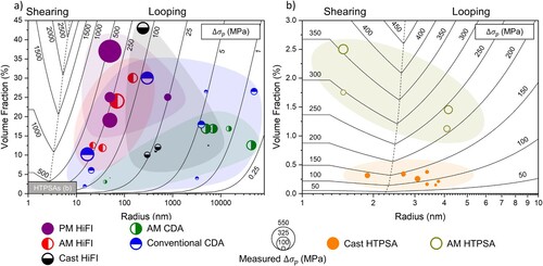
Several AM alloys and other relevant alloys produced by conventional processing routes such as casting and powder metallurgy (PM) are plotted in , with the size of the data markers proportional to estimated in each alloy. In estimating
several assumptions are made: (i) the reported strength increments are assumed to be entirely from particle strengthening; (ii) when non-spherical precipitates are present, an area equivalent radius is computed from micrographs; (iii) when converting from Vickers microhardness (HV) values to yield strength, the
estimation is utilised [Citation233], and the Vickers microhardness of pure Al is taken as 200 MPa [Citation102]; (iv) the yield strength of pure Al is taken as 27 MPa [Citation234]. summarises all values plotted. Except for the HTPSAs, there is a tendency to overestimate the degree of strengthening with respect to Equations (10) and (11), indicating other strengthening mechanisms are likely at play. However, the trend of increasing strength with decreasing
and increasing ϕ is evident.
Table 4. Summary of compositions, , ϕ, and
values for data points shown in .
Schematically, demonstrates the most important microstructural features to consider when designing AM alloys with increased strength. For the HTPSAs, the most effective strategy for increasing alloy strength is to increase the volume fraction of strengthening precipitates. demonstrates that it is possible to achieve such an increase over the cast alloys by utilising the rapid cooling in AM processing, although there will be a fundamental limit to how much solute can be trapped in solid solution and thus a limit on the achievable precipitate volume fraction. A reduction in precipitate radius is most effective for strengthening of the AM HiFI alloys relative to their cast counterparts and makes them competitive with the PM HiFI alloys. The reduction in precipitate radius is readily achieved by microstructural refinement driven by rapid cooling in AM, Equation (4). Both reducing particle radius and increasing particle volume fraction are effective strategies for further strengthening the AM CDAs to make them competitive with conventionally processed CDAs, but as outlined in Section ‘Ceramic dispersion alloys’, there are still significant challenges in producing AM CDAs with a high volume fraction of homogeneously distributed particles.
Particle/Precipitate coarsening
Given that the interprecipitate spacing λ is inversely proportional to , this microstructural variable contributes strongly to the Orowan strength. Thus, for maintenance of high-temperature strength, λ must remain as small as possible during and after exposure of the microstructure to high temperatures. Similarly, in the particle cutting regime where strength is governed by
,
should remain as small as possible. Minimisation of λ and
suggests that Ostwald ripening, where larger particles grow at the expense of smaller ones resulting in a reduction of the precipitate number density, must be minimal. Ostwald ripening of spherical precipitates in a binary alloy is classically described by the Lifshitz, Slyozov, and Wagner (LSW) theory of coarsening, where the evolution of precipitate radius is given by [Citation245,Citation246]:
(12)
(12) where t0 is the onset time of the steady-state coarsening regime and K is the coarsening rate constant. When taking into account thermodynamic factors and nonzero solubilities of solute in each phase, K is expressed as [Citation247]:
(13)
(13) where D is the diffusivity of the solute species, σ is the precipitate-matrix interfacial free energy, and
and
are the equilibrium solubilities of the solute species in the precipitate and matrix, respectively. Since its introduction, the LSW theory has been generalised for multicomponent systems, but the proportionalities in K remain the same, albeit with diffusion tensors and concentration vectors replacing D and C [Citation248]. Thus, coarsening-resistant precipitates should have a low interfacial energy with the matrix and/or incorporate slow diffusing solutes. Solutes with a low solubility in Al are also excellent candidates given that low solubility implies large amounts of solute cannot easily diffuse through the Al matrix. The diffusivities at 400°C and maximum solubilities of several commonly studied solutes in Al are given in (a). Optimal diffusivity solutes for coarsening-resistant strengthening phases are in the bottom left quadrant. Note that the generalised coarsening theories assume an evaporation-condensation mechanism and are valid for small volume fractions of spherical precipitates. Thus, they may not be strictly valid for the HiFI alloys discussed herein, where the intermetallic phase is often non-spherical, the volume fractions are >∼10%, and coarsening may occur by other mechanisms such as coagulation and coalescence [Citation249]. Future study is therefore required to better understand and model the coarsening behaviour of the AM HiFI alloys.
L12-strengthened alloys have generated significant interest for high-temperature applications within the casting community over the past two decades [Citation21–24]. The coherency of the L12 precipitates contributes to low interfacial energy and the incorporation of slow diffusing solutes such as Zr, V, and Mo into shells around Al3Sc precipitates contributes to their improved coarsening resistance [Citation108,Citation250–252]. Among their AM counterparts, which constitute the HTPSAs containing Zr/Sc, coarsening resistance has thus far been indirectly measured by ambient-temperature microhardness measurements as a function of aging, as shown in (a) for an LPBF-processed Al–4.52Mn–1.32Mg–0.79Sc–0.74Zr alloy [Citation106]. At short aging times Zr and Sc precipitate out of solid solution in the form of L12-nanoprecipitates, eventually reaching a peak strength. Beyond the peak the nanoprecipitates undergo Ostwald ripening, i.e. the interprecipitate distance λ increases and the strength decreases. Thus, the coarsening resistance of the strengthening L12-nanoprecipiates can be qualitatively determined from the strength evolution after peak aging; the most coarsening resistant distributions of nanoprecipitates maintain their strength for longer times at higher temperatures. As demonstrated in (a), as aging temperature increases, both the time to peak microhardness and time to onset of coarsening decrease.
Figure 18. Evolution of Vickers microhardness (VHN) for LPBF-processed (a) Al–4.52Mn–1.32Mg–0.79Sc–0.74Zr [Citation106] and (b) Al–10Ce–8Mn [Citation126] as a function of aging time and temperature. In (b) data for a cast Al–Cu–Mn–Zr (ACMZ) alloy are also plotted for comparison. Horizontal dotted lines are shown to aid the eye in comparison.
![Figure 18. Evolution of Vickers microhardness (VHN) for LPBF-processed (a) Al–4.52Mn–1.32Mg–0.79Sc–0.74Zr [Citation106] and (b) Al–10Ce–8Mn [Citation126] as a function of aging time and temperature. In (b) data for a cast Al–Cu–Mn–Zr (ACMZ) alloy are also plotted for comparison. Horizontal dotted lines are shown to aid the eye in comparison.](/cms/asset/ecbbd95b-030f-4387-b201-c14727a1acbf/yimr_a_1951580_f0018_oc.jpg)
Among the HiFI alloys, Al–Ce-based cast alloys are gaining popularity due to the inherent coarsening resistance of the Al11Ce3 eutectic reinforcing phase [Citation253,Citation254]. For example, after 12 weeks at 400°C, an Al-12.5 wt-% Ce alloy exhibited negligible microstructural coarsening and no measurable decrease in microhardness [Citation235]. The coarsening resistance was primarily attributed to the low solubility of Ce in the Al matrix ((a)) but was also attributed to the relatively low diffusivity of Ce in Al. High thermal stability has also been observed in Al–Ce-based AM alloys. Manca et al. reported on an Al–3Ce–7Cu alloy which showed no change in 250°C yield stress after 1 h exposure at 300°C, although the microhardness of the alloy steadily decreased at T > 250°C due to coarsening of the Al6.5CeCu6.5 and Al11Ce3 phases [Citation125]. Plotkowski et al. also reported on an Al–10Ce–8Mn alloy which, after an initial decrease, maintains a stable room-temperature microhardness after 200 h at 350–450°C as shown in (b). However, significant phase changes and microstructural evolutions occur during aging and the mechanisms for thermal stability are unclear [Citation126]. Nonetheless, this alloy maintains a higher microhardness for longer times at a given temperature than the HTPSA in (a), suggesting that design of HiFI alloys with coarsening-resistant phases and small values of λ may hold more promise.
The thermal stability of the microstructure in HiFI AM Al–Fe–V–Si alloys has not yet been reported, although the incorporation of slow-diffusing V into the Al12(Fe,V)3Si strengthening precipitates is expected to provide excellent coarsening resistance and high-temperature strength, as observed for rapidly solidified and consolidated alloys of the same composition [Citation31,Citation255]. The low solubilities of Co and Ni may contribute to coarsening resistance of refined and high-strength microstructures observed in binary AM Al–Co and Al–Ni alloys, but this has not been investigated yet [Citation40,Citation218]. Cast Al–Ni alloys have demonstrated coarsening resistance and thermal stability up to 400°C [Citation256–258]. Potential refinement of the coarsening resistant Al3Ni strengthening phase in AM makes this system an excellent candidate for future study. The Al–Ca–Ni–Mn system is another promising high-temperature AM HiFI alloy according to initial results by Shurkin et al. [Citation259]. Although Ca-rich eutectic structures spheroidise causing an initial 20% drop in hardness after annealing at 300°C for 3 h, the hardness of ∼160 HV is maintained during 3 h aging up to 400°C. Although it is more unconventional, Kang et al. reported on an AM HiFI alloy strengthened by quasicrystalline Al–Cu–Fe–Cr and Al–Fe–Cr phases which exhibits only a 5% reduction in room-temperature tensile strength and 14% reduction in microhardness after annealing at 570°C for 0.5 h [Citation260]. The remarkable retention of strength is likely due to the coarsening resistance of the quasicrystalline phases and merits further study.
The CDAs have inherent thermal stability due to the non-reactivity of the ceramic dispersions with the Al matrix at the service temperatures of interest, T < ∼500°C [Citation32–36]. For this reason, conventionally manufactured CDAs are considered ideal candidates for high-temperature service, and have been utilised in certain aerospace applications [Citation261]. However, investigations of the thermal stability of AM CDAs are severely lacking. One study has been published showing excellent elevated-temperature strength in ∼300 μm-thick Al–TiC (35 vol.-%) deposits [Citation155], and there are studies on the high temperature strengths of a bulk printed Al–Si–Mg with 2 vol.-% TiCN [Citation262] and Al–Cu–Mg–Ni–Fe–Ti–B with TiB2 dispersions [Citation263]. However, the latter two studies do not detail the coarsening behaviour of the ceramic dispersions. Although the ceramic dispersions are not likely to coarsen in service at T < ∼500°C, the welding literature suggests that significant particle coarsening and/or agglomeration by particle collision may occur in the melt pool during processing, where T is likely >1800°C for Al [Citation165,Citation264,Citation265]. Liquid lifetimes are longer for conventional welding compared to LPBF (∼1 vs. ∼0.001 s [Citation164,Citation264,Citation265]), but there is evidence to suggest that particle coarsening/agglomeration does occur during LPBF processing. For example, significant coarsening/agglomeration of 9 μm-Al2O3 particles has been noted during LPBF of CP-Al with 20 wt-% Al2O3 [Citation194].
Extended solid solubility of solutes in AM processing provides new opportunities for enhanced particle strengthening and coarsening resistance. Supersaturation of Zr and Sc in AM HTPSAs allows for higher volume fractions of coarsening-resistant L12-nanoprecipitates upon aging when compared to cast alloys (0.3 vs. ∼1–3 %), as summarised in . Higher values of ϕ have a positive effect on all the particle strengthening mechanisms we have highlighted and as the L12-nanoprecipitates have inherent coarsening resistance, the added strength is expected to be maintained at elevated temperatures. There are a few studies where Zr/Sc levels have been increased well beyond their solubility limits, but there is limited information reported on the degree of Zr/Sc supersaturation and its evolution with aging time. Such studies are critical for designing appropriate heat treatments such that maximum strengthening may be obtained.
Beyond L12-nanoprecipiates, there is also an opportunity for development of alloys with high volume fractions of coarsening-resistant α-Al(Fe,Mn,Mo)Si precipitates. These precipitates have been reported to form in cast Al–7Si–0.5Cu–0.3Mg alloys at 540°C, and are stable at the 400–500°C [Citation212,Citation266]. The presence of the nm-scale precipitates increases the tensile yield strength by 25% and decreases the minimum creep rate by a factor two. The formation of α-Al(Fe,Mn,Mo)Si precipitates has also been reported in dilute cast Al–Zr–Sc–Er–Mo–Mn alloys, where they partially contribute to the creep resistance [Citation250,Citation267,Citation268]. The volume fraction of α-Al(Fe,Mn,Mo)Si in these cast alloys is limited by the maximum solid-solubilities of Mn (0.62 at.-%) and Mo (0.07 at.-%). This solubility limitation may be overcome through precipitation aging of as-printed AM alloys highly supersaturated in Mo and Mn.
There are several cast Al alloy systems whereby coarsening resistance of strengthening precipitates is enhanced by interfacial solute segregation: Zr segregation to the shells of Al3Sc L12-nanoprecipitates in Al–Sc–Zr alloys [Citation107,Citation108,Citation252], Mn and Zr segregation to interfaces of metastable θ′-Al2Cu precipitates in Al–Cu–Mn–Zr alloys [Citation269–272], and segregation of Zr and V to interfaces of Al3Cu2Mg9Si7 Q-phase in Al–Cu–Mg–Si alloys [Citation273]. In each of these cases, the solute segregation either introduces a diffusion barrier to precipitate coarsening (lowers D in Equation (13)) and/or decreases the energy of the interface (σ in Equation (13)). Extended solute solid solubility in AM processing potentially provides a pathway for further enhancing the coarsening resistance in these systems by increasing the matrix supply of segregating solute.
Load transfer
The increment in yield stress provided by transfer of load from the matrix to a stiff fibre reinforcing phase can be represented by the expression [Citation274]:
(14)
(14) where
is the strength increment provided by load transfer, Vf is the volume fraction of reinforcing fibres, s is the aspect ratio (length:radius) of the fibres, and σint is the strength of the matrix/fibre interface. This shear-lag model is valid for short fibres where tensile load transfer at the fibre ends is significant, assumes the fibres are aligned along the loading direction, and assumes that composite yield occurs when the stress carried by the matrix exceeds the strength of the matrix/fibre interface. Although this shear-lag model is not directly applicable for AM components where reinforcements will almost certainly be non-aligned and may not be in the form of fibres, it has been widely adopted to describe load partitioning in particle reinforced composites with a wide variety of particle aspect ratios [Citation275], and thus sets forth relevant microstructural parameters for the consideration of load transfer: (i) given the linear dependence of
on Vf, load transfer is expected to be applicable to alloys with a significant volume fraction of reinforcement, which includes the AM HiFI alloys and some of the AM CDAs containing greater than a few vol.-% reinforcement; (ii) the strength of the matrix/reinforcement interface is critical, implying that AM CDAs with reactive dispersions, , may not be ideal candidates for load transfer strengthening, given the tendency for undesirable phase formation at the matrix/reinforcement interface; (iii) spherical particles with low aspect ratio common to the AM CDAs will not be as efficient carriers of load as the high aspect ratio fibre-like intermetallic networks in the HiFI alloys. We note that the value of
is difficult to obtain, but is expected to be on the order of ∼100 MPa (measured as 133 MPa for Al/SiC [Citation276]), and is likely higher for semi-coherent and coherent interfaces.
Since is difficult to measure, the precise contributions of load transfer to the strength of AM CDAs or HiFI alloys has not been reported with great accuracy. In a study of an Al–TiC AM CDA with 35 vol.-% TiC, Lin et al. reported that load transfer to the TiC nanoparticles contributed 57% of the measured strength increment when considering Orowan, grain size, and load transfer strengthening [Citation155]. However, the authors note the analysis is reliant on a purely hypothetical value of the Al/TiC interfacial strength. The use of in-situ neutron and X-ray diffraction would be helpful in future studies for precisely determining the degree of load transfer, as was reported for cast Al–Ce alloys [Citation253].
The effect of elevated temperature exposure on the load transfer mechanism is not clear, but the strength of the matrix/reinforcement interface and reinforcement aspect ratio should remain as high as possible, suggesting that morphological changes, i.e. spheroidisation, coarsening, and the resulting loss of coherency – if applicable – of the reinforcement should be minimised. These considerations again point to a need for better understanding and modelling of the coarsening behaviour of the AM HiFI alloys.
Measurements of high-temperature strength
Although measurements of ambient-temperature mechanical properties are commonly reported for AM Al alloys [Citation101], there is little published data on the high-temperature mechanical properties. shows published yield stresses and elongations for various high-temperature AM Al alloys as a function of temperature. Tests performed in tension are shown using solid symbols and tests performed in compression are shown using hollow symbols. Elongation values are not plotted for compression tests. (b) shows detail of yield stress vs temperature. Properties for an Al–Si–Mg alloy are also included, as this is the most widely studied Al alloy in AM. summarises the sample heat treatments prior to testing, hold times at the test temperature prior to applying load (soak time), the strain rates utilised during testing, and the loading orientation relative to the build direction. These test parameters are important when comparing tests performed on AM samples at elevated temperatures where microstructures may be strain rate sensitive and evolve rapidly with time.
Figure 19. (a–b) Yield strength and (c) elongation as a function of temperature for LPBF-processed Al–10Ce–8Mn [Citation126], Al–2.9Mg–2.1Zr [Citation47], Al–14.1Mg–0.47Si–0.31Sc–0.17Zr [Citation115], Al–8.6Cu–0.45Mn–0.90Zr [Citation65], Al–12.1Si–1.4Ni–1.4Fe [Citation277], Al–2.3Cu–1.6Mg–1.1Ni–0.8Fe–3.5Ti–1.2B [Citation263], Al–10Si–0.3Mg with 2 vol.-% 2–4μm-TiCN [Citation262], CP-Al with 35 vol.-% TiC [Citation155], and Al–29.9Nd–7.6Ni–3.1Co [Citation278]. For comparison, data for AM Al–10Si–0.3Mg are also shown [Citation279]. Filled symbols are tensile data and hollow symbols are compressive data. Elongation values are not given for the compressive data. (b) shows detail of the low stress region in (a). gives testing parameters for all data shown.
![Figure 19. (a–b) Yield strength and (c) elongation as a function of temperature for LPBF-processed Al–10Ce–8Mn [Citation126], Al–2.9Mg–2.1Zr [Citation47], Al–14.1Mg–0.47Si–0.31Sc–0.17Zr [Citation115], Al–8.6Cu–0.45Mn–0.90Zr [Citation65], Al–12.1Si–1.4Ni–1.4Fe [Citation277], Al–2.3Cu–1.6Mg–1.1Ni–0.8Fe–3.5Ti–1.2B [Citation263], Al–10Si–0.3Mg with 2 vol.-% 2–4μm-TiCN [Citation262], CP-Al with 35 vol.-% TiC [Citation155], and Al–29.9Nd–7.6Ni–3.1Co [Citation278]. For comparison, data for AM Al–10Si–0.3Mg are also shown [Citation279]. Filled symbols are tensile data and hollow symbols are compressive data. Elongation values are not given for the compressive data. (b) shows detail of the low stress region in (a). Table 5 gives testing parameters for all data shown.](/cms/asset/4bd915c3-b8c5-48cf-8159-a9cf2acbe597/yimr_a_1951580_f0019_oc.jpg)
Table 5. Summary of test parameters for data in .
As a general trend, tensile stresses decrease and elongations increase with increasing temperature, as expected due to increasing dislocation mobility, potential dislocation climb, and grain boundary sliding. The reported yield strengths for tests performed in compression are remarkably high, ∼600 MPa higher at room temperature when compared to tensile results from other alloys. The effect is less pronounced with increasing temperature, but the yield strengths are still ∼100 MPa higher at 400°C. Direct comparison with tensile data is not possible, due to the expected defect sensitivity of the three alloys for which compression data is presented. All contain significant volume fractions of brittle intermetallics or ceramics; if tested in tension their yield strengths are likely to be lower. For the AM Al–TiC CDA (35 vol.-% TiC), the data were collected from micropillar compression [Citation155]. Thus, the high strength relative to the tensile data may also be related to size effects. The authors in Ref. [Citation155] acknowledge that strengthening from high strain rates may also be present. The strain rate was 2 × 10⁻³ s−1, higher than the ASTM E21 standard ∼1 × 10⁻⁴ before 2% strain and ∼1 × 10⁻³ s−1 after 2% strain for elevated-temperature tension tests. Nevertheless, the high volume fraction of TiC reinforcement contributes to significant strengthening by Orowan looping, load transfer, and a grain refinement effect. The remarkable compressive strength for Al–29.9Nd–7.6Ni–3.1Co is likely due to the exceptionally high volume fraction of intermetallic phases (estimated as ∼50–60% by the present authors) which contributes Orowan and load transfer strengthening [Citation278]. The Al–Si–Fe–Ni alloy also contains a significant volume fraction of intermetallic (∼10–15%) which likely contributes to its strength by the same mechanisms [Citation277]. Note that strain rate effects may also be present in the Al–Si–Fe–Ni results, as the alloy was tested at strain rates two to three orders of magnitude greater than given in the ASTM E21 standard.
Focusing on the tensile data, all of the high-temperature alloys possess higher room-temperature strength than the AM Al–Si–Mg alloy, which will act as a baseline comparison dataset. The high-diffusivity Si in the reinforcing eutectic network of this alloy contributes to rapid coarsening and decrease in strength by reduction of Orowan strengthening contribution above ∼200°C. The grain refinement by Al3(Zr,Sc) [Citation47,Citation65,Citation115], solid-solution strengthening by Mg and/or Mn [Citation47,Citation65,Citation115,Citation126], and refined intermetallic networks [Citation65,Citation126] all contribute to the improvement in strength in the AM HTPSAs and HiFI alloys. As the tests are performed on as-printed alloys, strengthening by Al3(Zr,Sc) nanoprecipitates in the HTPSAs with Zr/Sc is assumed to be negligible. Note that the Al–Cu–Mn–Zr alloy constitutes both a HTPSA and HiFI alloy, as it contains Zr for grain refinement as well as a network of eutectic θ-Al2Cu which is expected to contribute to strengthening.
The HiFI alloys (including Al–Cu–Mn–Zr) maintain their strength advantage over Al–Si–Mg up to 300–400°C, however the HTPSAs experience rapid drops with increasing temperature. The drop in strength begins at 150°C for Al–Mg–Zr, and 250°C for Al–Mg–Si–Sc–Zr. As the Al–Mg–Si–Sc–Zr alloy contains nearly four times more Mg than Al–Mg–Zr (14.1 vs. 3.6 wt-%), the increased solid-solution strengthening likely contributes to the enhanced thermal stability. Griffiths et al. found that Al–Mg–Zr samples aged at 400°C for 8 h and containing Al3Zr nanoprecipitates had lower strength than as-printed alloys at test temperatures >150°C, attributed to coarsening of precipitates along grain boundaries in Al–Mg–Zr during aging, which decreased their ability to prevent grain boundary sliding during deformation [Citation47]. The grain boundary precipitate coarsening mechanism also likely contributes to the drop in alloy yield strength at increasing temperatures for the HTPSAs with Zr/Sc.
Among the AM CDAs, grain refinement by TiB2 in Al–Cu–Mg–Ni–Fe–Ti–B and TiCN in Al–Si–Mg likely provides an increment in tensile strength [Citation262,Citation263]. In both studies, the ceramic-modified AM alloys outperformed their un-modified wrought and cast counterparts at elevated temperatures, suggesting that the dispersions aid in high-temperature performance by pinning grain boundaries. However, note that a rapid drop in strength is still observed for the Al–Cu–Mg–Ni–Fe–Ti–B alloy above 200°C () as its strengthening Al2Cu and Mg2Si precipitates coarsen.
Based on existing data, the AM HiFI alloys and AM CDAs (with >10% volume reinforcement) appear to be most promising for high-temperature performance – provided that ductility values are improved upon at T < ∼200°C as discussed in Section ‘Ductility’ – although the mechanisms by which they achieve thermal stability should be the subject of future study. In alloys with a thermally stable eutectic such as Al–Ce [Citation46], the morphology of the eutectic does not change substantially with elevated temperature. Thus, the microstructural parameters governing strengthening by Orowan looping and load transfer remain constant. However, in other cases such as Al–Ce–Mn the microstructure is highly unstable and evolves substantially with time, yet strength at elevated temperatures is retained [Citation126]. Understanding the relative contributions and importance of the strengthening mechanisms outlined in this chapter will significantly aid in the design of alloys with improved high-temperature properties. Aged HTPSAs with Zr/Sc also merit further investigation, with the goal of optimising microstructures such that L12-nanoprecipitate strengthening is maintained at temperatures >250°C.
Creep behaviour
Creep is time-dependent plastic deformation taking place when Th ≥ 0.4–0.5 (Th = T/Tm, where Tm is the absolute melting temperature, 933 K for Al) and applied loads below the yield stress. The steady-state or minimum creep rate can be summarised by the following expression [Citation280]:
(15)
(15) where
is the minimum strain rate, A′ is a material-dependent constant, D is diffusivity, Ω is the atomic volume, σ is the applied stress, G is the shear stress, k is the Boltzmann constant, T is the absolute temperature, b is the burgers vector, d is the average grain diameter, and m′ and n′ are creep mechanism-dependent constants. Creep deformation occurs by either diffusional creep, active at high Th and low stresses, or dislocation creep, active at high stresses. The values of A′, m′, and n′ are governed by the active creep mechanism(s). For diffusional creep m′ = 2–3 and n′ = 0. For dislocation creep m′ = 0 and n′ = 2–6. When discussing experimental data, Equation (15) is often expressed in the form [Citation280]:
(16)
(16) where the constant A incorporates all material-dependent terms, n is the stress exponent, and Qc is the creep activation energy, which for Al is equal to the activation energy for self-diffusion, 142 kJ mol−1 [Citation281]. For diffusional creep n = 1–2, and for dislocation creep n = 3–7.
Knowledge of material creep behaviour is critical for engineering design of components subjected to stress and elevated temperature for long periods of time. However, creep studies on AM Al components are almost nonexistent, with three in-depth studies published on Al–Mg–Si [Citation48,Citation49,Citation279], and a single study on a high-temperature HTPSA, Al–Mg–Zr [Citation47]. We will review the results of these studies in a discussion of mechanism-dependent considerations for design of creep-resistant AM high-temperature alloys.
Diffusional creep
Diffusional creep occurs by mass transport along grain boundaries (Coble creep, m′ = 3), and through grain interiors (Nabarro-Herring creep, m′ = 2), and is accommodated by grain boundary sliding (GBS). Although both diffusional mechanisms are active at high Th, Coble creep dominates at lower temperatures and is dependent on DGB, the self-diffusivity along grain boundaries, while Nabarro-Herring creep dominates at higher temperatures and is dependent on DL, self-diffusivity in the lattice. According to Equation (15) the creep strain rate is inversely proportional to dm′, thus the grain size will have the greatest effect on the diffusional creep rate. When compared to conventional cast alloys with mm-scale grains, the micron- and submicron-scale grain sizes present in current AM high-temperature alloys (e.g. in ) are expected to provide significantly less resistance to diffusional creep. Indeed, contributions from GBS were reported in AM Al–Mg–Zr with ∼800 nm equiaxed grains and ∼1 × 10 μm columnar grains, where coarsening of grain boundary precipitates either during annealing at 400°C or in situ during the creep test led to reduced creep resistance at 260°C [Citation47]. The reduction in creep resistance through an increase in GBS was attributed to the reduced grain boundary pinning effect by the coarsened grain boundary precipitates.
As AM alloys are likely to have refined grain structures which contribute to the yield strength at ambient and elevated temperature, resistance to diffusional creep should ideally be achieved by methods other than increasing the grain size. Based on Equation (15), this may be achieved by three strategies: decreasing DL for Nabarro-Herring creep, DGB for Coble creep, or by decreasing the tendency for accommodating GBS. Of these strategies, the latter two appear to be achievable based on existing literature. The presence of precipitates such as Al3(Zr,Sc) along grain boundaries has been shown to pin grain boundaries and prevent grain growth in AM high-temperature alloys [Citation70,Citation98,Citation115,Citation116] () and ceramic particles are utilised to the same effect in cast Al alloys [Citation203], although the effect has not been studied in AM CDAs. The pinning effect is also expected to decrease GBS during creep and may also reduce the effective grain boundary diffusion rate. The introduction of slow-diffusing solutes into the Al matrix () may also be an effective strategy for reducing GBS by the solute drag mechanism [Citation282–284].
Dislocation creep
In the precipitate-strengthened Al alloys discussed herein, dislocation creep likely occurs by a climb-glide mechanism. In this mechanism, dislocations bypass the precipitates by climbing out of their glide planes rather than shearing or looping around them, as the applied stress is below . Climb is a vacancy-mediated process, therefore the D term for dislocation creep in Equation (15) is DL, the lattice self-diffusivity. There is also an energy associated with the increase in dislocation line length necessary for climb over the precipitate.
Below a certain applied stress, dislocations will not be able to bypass obstacles and dislocation creep will not be macroscopically measurable, denoted as the temperature-dependent threshold stress . The theoretical upper limit for
is the Orowan stress but in practice, the threshold stress value is significantly lower because thermally activated climb is possible during creep. In Equation (16) a threshold stress may be incorporated by replacing the
term with a (
) term. Valid methods for increasing
therefore include maximising the distance over which a dislocation must climb, i.e. increasing the precipitate size or aspect-ratio, and increasing the Orowan stress through microstructural manipulation, as described in Section ‘Particle strengthening’.
Precipitate/dislocation interactions may also influence . For coherent precipitates, lattice mismatch strains in the matrix trap dislocations on the departure side as they climb over precipitates [Citation285,Citation286]. Higher stresses are needed for the dislocations to break free, and the threshold stress increases with increasing lattice parameter misfit. This effect has been widely studied in cast L12 nanoprecipitate-strengthened alloys, where incorporation of various solutes into the nanoprecipitates either increases or decreases their lattice misfit and the resulting creep threshold stress [Citation287–291]. This behaviour is also verified in AM Al–Mg–Zr strengthened by L12-nanoprecipitates, where high values of the stress exponent suggested a
for dislocation creep [Citation47]. For incoherent particles there is an analogous mechanism whereby dislocations are trapped on the departure side by an attractive force stemming from spreading of the dislocation core [Citation292,Citation293], widely studied in cast Al alloys strengthened by incoherent Al2O3 dispersoids [Citation32,Citation294].
Load transfer effects are also expected to be significant in the AM HiFI alloys and AM CDAs with appreciable volume fraction of reinforcement, as observed in a rapidly solidified and consolidated Al–Fe–V–Si alloy with ∼27 vol.-% Al13(Fe,V)3Si dispersoids [Citation30]. Load transfer from matrix to reinforcement decreases the overall effective stress on the matrix and decreases the composite strain rate but intensifies the stress at portions of the matrix/reinforcement interface [Citation295,Citation296]. Thus, plastic strain largely occurs along this interface during creep deformation via diffusional flow and dislocation motion. The high stress along the interface also suggests that cavitation or debonding may occur. For design of creep-resistant alloys where load transfer is active, strong interfacial bonding and restriction of diffusional flow and/or dislocation motion along the matrix/reinforcement interfaces is therefore desired.
The few existing creep studies of AM Al–Mg–Si alloys show similarities to the creep behaviours of cast Al–Si alloys [Citation297,Citation298] and the widely studied Al metal matrix composites (MMCs) [Citation37] in that they exhibit abnormally high values of the stress exponent (n > 7, Equation (16)) and/or creep activation energy for dislocation climb (Qc > 142 kJ mol−1, Equation (16)), suggesting the presence of a threshold stress [Citation48,Citation49,Citation279]. The microstructures of Al–Si alloys closely resemble those of MMCs, with a dispersion of a hard and stiff phase (Si eutectic structures, platelets, and particles) in a weak Al matrix, so the similarities in creep behaviours are not surprising. At present, the mechanisms which contribute to the threshold stress are not clear, but likely involve dislocation/reinforcement interactions as described earlier in this section. As in the MMCs, it is also likely that load transfer plays a role given the high volume fraction (∼12%) of Si reinforcement [Citation275]. Note that the creep studies of AM Al–Si–Mg were performed at stress values near or even above the alloy yield point, therefore dislocation glide is expected to be a major contributor to the measured creep behaviour.
Like the solute drag effect on grain boundaries, solute drag may also affect dislocation motion during creep. At elevated temperatures, solutes may become mobile and move along with dislocations. This phenomenon creates a drag effect on dislocation motion, provided that the diffusion rate of the solute is comparable to the dislocation velocity. In Equation (15), the D term becomes Dsol, the diffusivity of the solute, and the experimentally observed stress exponent n in Equation (16) is close to 3. In the single creep study of an AM Al–Mg–Zr alloy, Griffiths et al. measured a stress exponent of n = 3, consistent with solute drag creep, likely due to the high Mg concentration of ∼3.6 wt-% in the matrix [Citation47]. This effect is also commonly seen in ambient-temperature mechanical tests of AM HTPSAs containing Mg, where Mg is mobile enough at room temperature to produce a dragging effect on dislocation motion [Citation79,Citation85,Citation92,Citation93,Citation338,Citation340]. This effect manifests as serrated flow after yielding as dislocations are repeatedly arrested by and break away from solutes, known as the Portevin-Le Chatelier (PLC) effect. The PLC effect has not been observed in high-temperature testing of AM Al alloys.
In summary, there is an urgent need for understanding the creep response for various AM high-temperature Al alloys. Given the refined grain sizes of many of the potential high-temperature AM alloys discussed in this review, particular attention should be paid to suppressing diffusional creep mechanisms when designing creep-resistant alloys. Sparse creep studies on the AM HTPSAs have already indicated that diffusional mechanisms such as GBS play a significant role in reducing creep strength [Citation47]. Strategies for diffusional creep mitigation include introduction of slow-diffusing solutes for drag at the grain boundaries and utilisation of second phases for grain boundary pinning. Maximising the threshold stress effect will likely be key in improving the dislocation creep resistance of AM high-temperature alloys. As the creep threshold stress is analogous to the Orowan stress, microstructural manipulations which increase the Orowan stress in Section ‘Particle strengthening’, i.e. increasing ϕ and decreasing , are likely to have a positive effect on the creep resistance. For the AM HTPSAs, there are expected to be additional competing effects on the threshold stress from precipitate size and coherency. For the AM HiFI alloys and AM CDAs, the volume fraction, aspect ratio, and orientation of reinforcing phases are likely to have a strong effect on additional load transfer effects. Each of these effects deserves future investigation for optimisation of creep resistance.
Ductility
Several factors have been shown to contribute to reduced ductility in traditional AM Al alloys such as porosity, residual stresses, and surface roughness [Citation10,Citation16]. However, the potential AM high-temperature Al alloys discussed thus far have relatively low defect densities as achieved by various mechanisms outlined in Section ‘Solidification, microstructure, and processing’: nucleation of equiaxed grains by Al3(Zr,Sc) in AM HTPSAs with Zr/Sc which reduce hot cracking, use of near-eutectic alloy compositions in AM HIFi alloys to reduce alloy solidification ranges, and nucleation of equiaxed grains by TiB2, LaB6, and other dispersions in AM CDAs. Each of these factors is expected to contribute favourably to ductility. Ambient-temperature ductilities are indeed impressive for AM HTPSAs (3–35%, average of ∼16%) and moderate for the AM HiFI alloys (1–12%, average of ∼8%) and AM CDAs (3–18%, average of ∼8%), as shown in (c).
Besides low defect densities, there are other microstructural features common to the potential high-temperature alloys discussed herein which are favourable to ductility. The bimodal grain structures in AM HTPSAs allow for strain partitioning between bands of equiaxed grains and columnar grain regions, improving alloy strain hardening ability and producing a strength-ductility synergy [Citation85]. The refined intermetallic structures in AM HiFI alloys may provide increased ductility when compared to their cast counterparts, as the refined networks are less likely to lead to stress concentrations and crack initiation sites. For example, an AM Al–Cu–Mn–Zr alloy with 9 wt-% Cu had much higher ductility (11% vs. 3%) than a cast alloy with the same Cu content [Citation65]. This was partially attributed to the refined θ-Al2Cu network in the AM alloy, whereas the brittle and coarse θ-Al2Cu precipitates along grain boundaries in the cast alloy acted as crack initiation sites that limited the tensile ductility [Citation299]. New deformation mechanisms involving co-deformation of the matrix and nanoscale θ-Al2Cu lamellae are reported to contribute to excellent plasticity in laser re-melted Al–Cu alloys of eutectic composition (32.7 wt-%) [Citation300–302]. Although the θ-Al2Cu is expected to coarsen significantly at elevated temperatures given the high diffusivity of Cu, these results offer exciting promise for increased ductility in AM HiFI alloys with nanoscale intermetallic networks.
Even when considering novel deformation mechanisms and potential ductility enhancements in AM alloys, it may become necessary in material selection to balance high-temperature strength with ambient-temperature ductility. This balance may be achieved through the selection of a particular high-temperature alloy type. For example, given their high ductilities but lower high-temperature strengths in , AM HTPSAs may be more suitable for components under tensile stress that are not exposed to temperatures above ∼250°C. Conversely, given their lower ductilities and higher high-temperature strengths, AM HiFI alloys and CDAs may be more suitable for components under compressive stress that are exposed to temperatures >250°C. Design of heat treatments may also be used to control ductility. In AM Al–Si–(Mg) alloys, heat treatments which spheroidise and coarsen microstructural features increase ductility at the expense of strength [Citation43,Citation113]. Similar heat treatments for increased ductility are likely viable for the AM HiFI alloys and CDAs.
In broad terms, ambient-temperature mechanisms for improving ductility discussed thus far i.e. accommodating dislocation movement and reducing stress concentrations, are expected to translate to elevated temperatures, where increased dislocation mobility and recovery processes lead to further increases in ductility ((c)). At elevated temperatures, however, thermally assisted void growth and coalescence leading to transgranular or intergranular fracture may reduce ductility, particularly in the creep regime. We now discuss further observations at ambient-temperature which are a concern for high-temperature ductility and fracture in AM alloys.
Fracture in AM Al–Si–Mg alloys mechanically tested at ambient temperatures is commonly observed along the HAZ of the MPB regions, where spheroidisation and breakdown of the Si eutectic network occurs. The spheroidisation creates a weak region in the microstructure where strain localisation leads to dislocation pileup and void nucleation at the Si/Al matrix interfaces, which is detrimental to the alloy ductility [Citation303–306]. This void nucleation mechanism is observed to translate to high-temperature tensile and creep tests, where the void nucleation and growth rate increases with temperature [Citation279,Citation307]. shows examples from an AM Al–Si–Mg alloy tested at both ambient and creep conditions. Fracture preferentially occurs along the MPBs, visualised by remnants of the laser tracks on the fracture surface. The MPB regions in the high-temperature AM alloys are expected to be equally detrimental to alloy ductility at high temperatures. Plotkowski et al. observed that room-temperature fracture preferentially occurs along MPBs containing coarsened precipitates in an Al–10Ce–8Mn HiFI alloy, leading to a low elongation of 1.14 ± 0.83% [Citation126]. Coarsened Al2CuMg particles at the MPBs of an AM Al–Mg–Mn–Sc–Zr HTPSA contributed to reduced ductility in the heat-treated state [Citation78].
Figure 20. Fracture surfaces of an LPBF Al–10Si–0.3Mg alloy following (a,c) ambient-temperature tensile test and (b–d) creep test at 300°C and 117 MPa [Citation279]. The laser tracks from LPBF processing are clearly visible, with larger voids evident after creep. Used with permission from Elsevier.
![Figure 20. Fracture surfaces of an LPBF Al–10Si–0.3Mg alloy following (a,c) ambient-temperature tensile test and (b–d) creep test at 300°C and 117 MPa [Citation279]. The laser tracks from LPBF processing are clearly visible, with larger voids evident after creep. Used with permission from Elsevier.](/cms/asset/1fd86e68-4676-4042-a41a-b7280b226490/yimr_a_1951580_f0020_ob.jpg)
There are further ductility limiting considerations with the AM CDAs. The formation of unwanted and brittle reaction products such as oxides and aluminium carbides, , contributes to a significant loss of ductility at room temperature in AM Al–Si–Mg with 12.5 vol.-% SiC [Citation158] and CP-Al with 4 vol.-% Al2O3 [Citation239], as the brittle phases act as stress concentrators and crack initiation sites. Similarly, poor bonding between ceramic dispersions and Al matrix leads to crack initiation sites as the volume fraction of reinforcement increases, as observed in an Al–Si–Mg alloy with varying levels of B4C and Ti powders [Citation174] and an Al–Si–Mg alloy with varying levels of LaB6 nanoparticles [Citation151]. At elevated temperatures, the crack initiation sites in these AM CDAs are expected to be efficient void nucleation sites.
We may also turn to the rapid solidification literature for insight into factors influencing high-temperature ductility. A main limitation of advanced high-temperature Al alloys produced by rapid solidification processing and consolidation, such as Al–Cr–Zr and Al–Fe–V–Si alloys, is a ductility trough between ∼100 and 300°C [Citation255,Citation308]. The ductility trough is attributed to dynamic strain aging (DSA) during deformation, which is like solute drag creep and the PLC effect in that solutes diffuse along with and occasionally arrest dislocations. Since the ductility trough exists at the intended service temperature for these alloys, they have been limited in commercial applications where high-temperature ductility is required, despite their excellent strength and thermal stability. A similar effect is expected for some AM HiFI alloys, especially those based on the Al–Fe–V–Si system and those with slow-diffusing solutes such as Cr. Chromium and Fe/V were identified as migrating species responsible for the DSA effect in Al–Cr–Zr and Al–Fe–V–Si alloys, respectively [Citation255,Citation308].
Fatigue
Reviews on challenges and opportunities associated with AM of fatigue-resistant materials have been published [Citation309,Citation310]. Several comprehensive studies on room temperature fatigue behaviour of SLM Al–Si alloys are also reported [Citation311–317]. Elevated-temperature fatigue studies of Al alloys are lacking and represent an opportunity for the fatigue and AM research communities to propose durable solutions for lightweight alloys in intermediate temperature regimes. AM studies on high-performance alloys (e.g. Ni-based superalloys [Citation318]) and the lower temperature studies on Al–Si-based alloys can provide expectations for elevated-temperature AM Al alloy classes considered in this review and are summarised below. Additionally, since the effect of surface oxidation on crack initiation behaviour is not a strong function of temperature in Al alloys, the underlying fatigue mechanisms are expected to be similar in a wider temperature range.
To investigate the fatigue behaviour of AM Al alloys for elevated-temperature applications, the microstructural features that are relevant for fatigue loading conditions need to be identified. Different microstructural features can affect the fatigue damage accumulation, crack initiation, and small and long fatigue crack propagation stages of the fatigue lifetime of a specimen or component in various competing manners [Citation319]. For example, the fine grains and other microstructural features that result from high cooling rates in additive manufacturing can be beneficial for crack initiation and the endurance limit but detrimental for crack propagation resistance, especially in the near-threshold regime [Citation320]. The heterogeneous microstructural features that result from AM provide an array of features that localise strain and thus become precursors for fatigue crack initiation [Citation321]. These features/sites are illustrated in and summarised below:
Porosity: Solidification and gas porosities that are common fatigue crack initiation features in cast Al alloys [Citation322] are also expected to be disproportionately important for determining the fatigue behaviour of elevated-temperature Al alloys. Indeed, Awd et al. determined that increased porosity in Scalmalloy© produced by DED methods resulted in a ∼30% reduction in fatigue strength relative to material processed by SLM [Citation84]. Furthermore, modelling of fatigue by Haridas et al. in AM Al–Cu–Mg–Zr determined that the amount and size of porosity significantly influenced the fatigue life, with a distribution of smaller pores increasing the lifetime of components [Citation323]. Their predictions were validated by experimental results. Keyhole porosity, if present, could also be relevant for additive microstructures, indicating potential challenges for high-temperature alloys containing volatile Mg, Zn and/or Mn, the vaporisations of which are expected to increase the tendency for keyholing as discussed in Section ‘Vaporisation of solute elements and porosity’. Near-surface pores are especially detrimental [Citation309,Citation311] and traditional damage-tolerant approaches can be applied to assess the effect of porosity on fatigue life. In addition to reducing the fatigue limit, porosity can also increase the scatter in fatigue behaviour.
Lack of fusion defects: Incomplete solidification of metal powder can lead to the formation of agglomerates that can become stress raisers that initiate fatigue cracks. Lack of fusion defects was found to act as fatigue crack initiation site in AM Al–Cu–Zr–Sc [Citation323].
Inclusion particles: Hard inclusions can lead to ‘fish-eye’ type crack initiation especially in the very high cycle fatigue regime (>107 cycles to failure) [Citation324]. The hard ceramics dispersion in the AM CDAs discussed herein may thus present a challenge as fatigue crack initiation sites, especially if there is poor matrix/dispersion bonding.
Surface roughness: It is well known that additive microstructures lead to higher surface roughness due to partially melted powder at the specimen surface that provides stress concentrations for initiation of fatigue cracks [Citation309]. In situations where machining or polishing of the surface is possible, significant improvement in fatigue life can be obtained [Citation325], especially in the long fatigue lifetime regime.
Melt pool boundaries (MPBs): The anisotropy in monotonic and fatigue properties with build orientation is well-reported, with properties along the build direction being inferior [Citation309]. Microstructural gradients around MPBs can provide additional drivers for fatigue crack initiation especially when (a) low toughness intermetallics form at the melt pool boundary, as in the AM HiFI Al–Ce–Mn alloy [Citation126] and (b) under creep-fatigue loading conditions. Especially in creep-fatigue loading conditions, the MPBs and the associated HAZs provide a metallurgical notch for strain localisation, as discussed in the previous section on ductility.
Persistent slip bands: When the common strain localising features like porosity are removed by post-processing treatments like hot isostatic pressing, other microstructural defect precursors that form during cyclic loading of fcc alloys like persistent slip bands are expected to lead to fatigue crack initiation [Citation318,Citation321].
Figure 21. Microstructural features of relevance for fatigue crack initiation at elevated temperature for AM Al alloys: (a) near-surface porosity, (b) lack of fusion defects, (c) inclusions/hard particles, (d) surface roughness, (e) persistent slip bands, and (f) melt pool boundaries.
Note: Features are not drawn to scale.
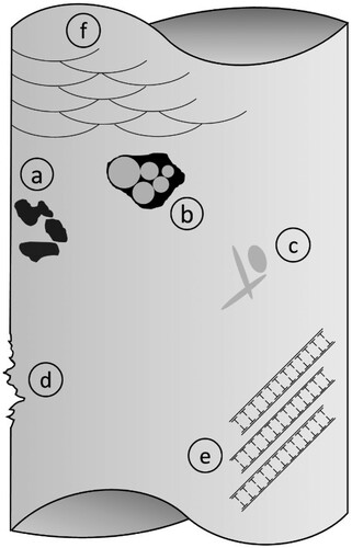
illustrates the defect populations and other intrinsic microstructural features that allow for the localisation of strain that is the precursor for fatigue crack initiation in AM Al alloys. In addition to the temperature and applied stress and strain levels, the fatigue loading conditions (low/high/very high cycle/creep/corrosion fatigue) and axiality will be relevant in understanding the specific mechanisms of fatigue damage such as slip irreversibility. Elevated temperature is expected to be uniformly detrimental to damage accumulation, crack initiation, and fatigue crack propagation with the exception of toughening of selected brittle phases.
Since additive processing allows the formation of non-equilibrium phases (e.g. [Citation326]), elevated homologous temperature will also provide conditions for rapid microstructure evolution towards the equilibrium phase(s) that needs to be accounted for and related to the fatigue behaviour. Some features such as columnar grains are unique to AM processing. While the effect of columnar grains on the fatigue crack initiation and growth behaviour is not well understood, a recent study on AM Al–Si alloys indicated that propagation of short fatigue cracks was not crystallographic and largely in mode I and normal to the loading direction [Citation327]. It is cautioned that the size of the artificial notch in this investigation was 200 μm, which is significantly larger than the grain size of the material. Studies on propagation of naturally initiated small fatigue cracks are warranted to understand the small fatigue crack/microstructure interactions. Finally, residual stresses are commonly considered a challenge with respect to thermal cracking during fabrication of AM parts and are typically managed by preheating the build plate [Citation10,Citation133,Citation136,Citation328]. Management of residual stresses through microstructural and heat treatments to improve fatigue life remain heavily underutilised. A better understanding of microstructure/elevated-temperature fatigue relationships will allow for the development of appropriate additive processing conditions and heat treatments leading to improved elevated-temperature fatigue response of this class of promising alloys.
Corrosion properties
Since AM high-temperature alloys are expected to be utilised in extreme environments, corrosion resistance must be considered in alloy design in addition to mechanical properties. Studies on corrosion behaviours of Al–Si–(Mg) alloys have been encouraging, as AM components display improved corrosion resistance over their cast counterparts due to refined grain and Si eutectic structures [Citation50,Citation51]. High-strength AM AA7075 and AA2024 alloys also have improved corrosion resistance, due to increased passivation and finer microstructural features than the wrought materials [Citation329,Citation330]. The improvement in corrosion resistance, of course, assumes that surface roughness and residual porosity in the AM components which may act as corrosion initiation sites are negligible. Of the three varieties of high-temperature Al alloys discussed in this review, corrosion properties have only been studied for AM HTPSAs. We review here the major findings of these studies, and comment on how they may relate to AM HiFI alloys and AM CDAs.
Like AM Al–Si–(Mg) alloys, the corrosion resistance of AM HTPSAs alloys is superior to cast alloys [Citation331]. The superior corrosion resistance is likely due to both grain and Al3(Zr,Sc) refinement in the AM alloy. The reduced grain size and increase in reactive grain boundary area likely increases the formation rate of a passivating oxide layer, decreasing the corrosion current [Citation332]. Al3(Zr,Sc) is among the known cathodic particles in Al (along with Al7Cu2Fe, Al3Fe, Al6Mn, Al3Ti, and Al2Cu), indicating it will preferentially corrode the surrounding Al matrix in an electrochemical cell, creating pits. The refinement of the particles reduces the formation of micron-scale electrochemical cells and the possibility of localised corrosion [Citation329,Citation330].
However, there is significant anisotropy in the corrosion properties of AM HTPSAs with Zr/Sc due to differing grain structures and morphologies of the MPBs throughout the build. Micron-scale Al3(Zr,Sc) particles tend to form along the MPBs due to lower cooling rates as discussed in Section ‘Grain structures’, indicating that these regions are more susceptible to corrosion and pitting attack. This assertion was verified by Zhang et al. for an Al–4.2 Mg–0.4Sc–0.2Zr alloy, where deep pitting was observed along the MPBs after intergranular corrosion testing in a solution of 3 wt-% NaCl + 10 mL L–1 HCl at 35°C for 24 h [Citation333]. Zhang et al. also noted that a change in scan strategy could be utilised to change the density of MPBs, with lower densities resulting in superior corrosion resistance [Citation334]. (a,b) summarises the corrosion anisotropies related to grain orientation and size [Citation335]. In the XY plane, transverse to the build direction Z, there is a preferred (111) grain orientation, whereas the XZ plane has a preferred (001) orientation. The XY plane has a higher average grain size and lower densities of grain boundaries, MPBs, and exposed Al3(Sc,Zr) particles. The refined grains and (001) orientation in the XZ plane indicates a faster passivation rate and less susceptibility to the initiation of pits than the XY plane, but once the passivating oxide breaks down, the higher density of Al3(Sc,Zr) particles and grain boundaries promotes propagation of deep pits in the XZ plane. The result is a high density of shallow pits in the XY plane and a low density of deep pits in the XZ plane, with both varieties preferentially forming at the MPBs ((c,d)). The deep pits are considered more detrimental to stress corrosion cracking susceptibility.
Figure 22. Summary of factors affecting corrosion resistance in AM HTPSAs with Zr/Sc. (a–b) the effect of build orientation and grain structure on corrosion of Al–4.2Mg–0.4Sc–0.2Sc [Citation335]; (c-d) a higher number density of shallower pits are formed on the XY build plane in Al–4.2Mg–0.4Sc–0.2Sc [Citation335]. The pits clearly outline the MPBs; (e–f) the effect of heat treatment of corrosion of Al–14.1Mg–0.47Si–0.31Sc–0.17Zr [Citation95], with heat treatment promoting the formation of deep pits. The build direction is along Z. Used with permission from Elsevier.
![Figure 22. Summary of factors affecting corrosion resistance in AM HTPSAs with Zr/Sc. (a–b) the effect of build orientation and grain structure on corrosion of Al–4.2Mg–0.4Sc–0.2Sc [Citation335]; (c-d) a higher number density of shallower pits are formed on the XY build plane in Al–4.2Mg–0.4Sc–0.2Sc [Citation335]. The pits clearly outline the MPBs; (e–f) the effect of heat treatment of corrosion of Al–14.1Mg–0.47Si–0.31Sc–0.17Zr [Citation95], with heat treatment promoting the formation of deep pits. The build direction is along Z. Used with permission from Elsevier.](/cms/asset/ddd9ebbd-cbc5-45c6-8948-9bca092ecd2c/yimr_a_1951580_f0022_oc.jpg)
Heat treatments also affect the corrosion resistance. The growth of cathodic micron-scale Al3(Sc,Zr) and/or Mg2Si precipitates during aging of Al–14.1Mg–0.47Si–0.31Sc–0.17Zr [Citation95] and Al–4.2 Mg–0.4Sc–0.2Zr [Citation333] alloys degrades the passivating oxide layer and leads to the formation of small electrochemical cells, increasing the corrosion currents relative to the as-printed alloys ((e,f)). From an alloy design perspective, it is fortunate that favourable properties for high-temperature mechanical strength (i.e. increased coarsening resistance of strengthening and potentially cathodic phases, Section ‘Particle/Precipitate coarsening’) are thus also favourable for increased corrosion resistance.
It is unclear whether the same corrosion mechanisms exist for AM HiFI alloys and AM CDAs, as the studies have not yet been performed. However, intermetallic refinement in the AM HiFI alloys and grain refinement in some AM CDAs offer promise that these alloys will have better corrosion resistance than their cast counterparts. Note that all studies are on aqueous corrosion of AM Al alloys. Although the passivating oxide film on Al is expected to provide excellent resistance to high-temperature corrosion, some studies of the oxidation behaviour for long periods of times at temperature may be justified.
Economic considerations
From an economic perspective, AM is favourable over conventional manufacturing for materials with high raw material and machining costs such as Ni-base superalloys and Ti alloys [Citation52]. Aluminium, which is inexpensive, castable, and machinable, does not fit these criteria. Therefore, the economic driving force for widespread use of Al alloys in AM must come from entirely new alloys with properties unique to the AM process, i.e. those which fill the opportunity space at elevated temperatures (). Such alloys would be ideal for 250–450°C applications where the current use of Ti alloys is an overdesign, e.g. aerospace components, turbocharger impellers, exhaust systems, and heat exchangers.
The role of economic driving force can be illustrated with a simplified schematic plot of component value vs. cost per part (). A component’s value is defined as its performance divided by cost. Analyses of cost per part as a function of number of parts are widespread in the AM community and show how reducing the overall cost of AM increases the size of production runs for which AM is economically feasible [Citation52,Citation336,Citation337]. Such analyses have sparked numerous studies aimed at decreasing recurring AM costs, such as the reuse of feedstock powders [Citation338]. Here we consider the cost and performance of a component rather than cost alone.
Figure 23. Schematic of the overall value of a part vs. number of parts for AM and conventional manufacturing processes. In the scenario shown, increasing the performance of the component by changing its material and processing expands the range of applications for which AM is economically favourable.
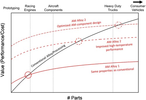
The total cost of manufacturing a component can be broadly split into two categories: one-time setup costs (capital equipment, floor space, personnel training, etc.) and recurring costs as manufacturing progresses (raw material, equipment time, power, maintenance, etc.). The one-time setup costs are typically higher for conventional processes as they involve purchase of larger amounts of capital equipment, tooling, and space. However, the recurring costs are often higher for AM largely because of the high cost of powder or wire feedstock relative to billets or cast ingots and increased manufacturing time per component [Citation339]. Performance metrics include the maximum alloy operating temperature, specific strength, corrosion resistance, creep strength, etc. An increase in performance metrics will tend to drive down the effective component cost. For example, an engine that may operate at higher temperature and with lower total weight will burn less fuel, driving drive down the effective cost of the component through energy savings.
demonstrates that on the basis of value, the ecomomic feasibility of Al for AM may be expanded into a broader application space if alloy performance is increased. In our schematic, by increasing the high-temperature performance of a component by switching to an AM Al alloy that cannot be produced by conventional methods, AM becomes feasible for a broader set of applications beyond simple protoyping. The applications are further expanded once the component design is optimised for AM, e.g. additional lightweighting by the use of complex shapes not obtainable using conventional processing. There will be cases, at least in the forseeable future, where conventional processing is preferred, such as for consumer vehicles in our example. Thus, we consider AM to be complimentary to conventional manufacturing methods. However, as industry moves towards energy-efficient design, whether by government mandate or a renewed focus on reducing enviromental impact, the lightweighting and energy effficiency upgrades from high-temperature Al alloys outlined in this review will provide a continued economic advantage for AM of Al [Citation38].
Conclusions and outlook
This review has identified and examined existing literature on several potential and promising high-temperature Al alloys manufactured using powder-based additive manufacturing (AM). We have broadly divided the alloys into three categories: Precipitation strengthened alloys with thermally stable strengthening phases (HTPSAs), alloys containing a high volume fraction (>10%) of intermetallics (HiFI), and alloys with a dispersion of non-reactive ceramic particles (CDAs). Most studies have focused on processing, microstructure, and ambient-temperature mechanical properties, but the field is severely underdeveloped in the evaluation of elevated-temperature mechanical properties, particularly creep and fatigue, as well as high-temperature oxidation and corrosion properties. Only ∼15% of the studies cited herein evaluate high-temperature mechanical properties. AM-based high-temperature Al alloys are well-positioned – from both a performance and economic standpoint – to fill a long-standing technological gap for structural materials in extreme environments in the 250–450°C range, therefore the authors suggest a strong future focus on these areas and have outlined in this review several important considerations for high-temperature performance.
The AM HTPSAs, often containing Zr/Sc, are the most comprehensively studied of the three categories thus far, with numerous studies devoted to processing/microstructure, heat treatment, mechanical properties (ambient- and elevated-temperature), and corrosion. The heat treatment of the alloys and refined grain structures lead to excellent ambient-temperature strength, but microstructural stabilities are not yet on par with their cast counterparts. The overall volume fraction of strengthening precipitates in AM HTPSAs will be limited by the maximum amount of solute that can be trapped in the matrix for subsequent aging. However, there are still many opportunities for heat treatment optimisation, including in-situ heat treatments, and improvement of high-temperature strength and coarsening resistance. Extensive casting literature on alloys containing L12 strengthening precipitates will likely provide inspiration for future research.
Studies of AM CDAs have been almost exclusive to processing, and the impacts of the various dispersion particles on the high-temperature mechanical properties are unknown. As the ceramic dispersions possess inherent thermal stability up to the melting point of Al, this class of alloys is deserving of more comprehensive evaluations including high-temperature strength and stability. Furthermore, as dispersion volume fractions are increased particle distribution and agglomeration issues should be addressed, as these will likely be limiting factors in AM CDA strengths.
Of the materials highlighted, initial high-temperature mechanical tests demonstrate that AM HiFI alloys show great promise for filling the 250–450°C technological gap. They are microstructurally similar to rapidly solidified (RS) and powder metallurgy (PM) Al alloys – the most thermally stable and strong high-temperature Al alloys developed to date – but do not suffer from the same geometrical constraints. Studies have been comprehensive but limited in number thus far. With further modifications of alloy chemistry, processing parameters, and evaluation of mechanical properties and high-temperature behaviour beyond tensile strength, (e.g. creep, stiffness, oxidation) AM HiFI alloys are poised to fulfil the commercial promise that was never realised for RS and PM Al alloys.
Acknowledgements
Research was co-sponsored the U.S. Department of Energy, Office of Energy Efficiency and Renewable Energy, Advanced Manufacturing Office and Vehicle Technologies Office Propulsion Materials Program. This manuscript has been authored by UT-Battelle, LLC under Contract No. DE-AC05-00OR22725 with the U.S. Department of Energy. The United States Government retains and the publisher, by accepting the article for publication, acknowledges that the United States Government retains a non-exclusive, paid-up, irrevocable, world-wide license to publish or reproduce the published form of this manuscript, or allow others to do so, for United States Government purposes. The Department of Energy will provide public access to these results of federally sponsored research in accordance with the DOE Public Access Plan (https://www.energy.gov/downloads/doe-public-access-plan). The authors would like to thank Sumit Bahl and Peeyush Nandwana for providing a technical review of this manuscript.
Disclosure statement
No potential conflict of interest was reported by the author(s).
Additional information
Funding
References
- Kusoglu IM, Gökce B, Barcikowski S. Research trends in laser powder bed fusion of Al alloys within the last decade. Addit Manuf. 2020;36:101489. https://doi.org/https://doi.org/10.1016/j.addma.2020.101489
- Kou S. Welding metallurgy. 2nd ed. Hoboken (NJ): Wiley-Interscience; 2002.
- Zhou SY, Su Y, Wang H, et al. Selective laser melting additive manufacturing of 7xxx series Al-Zn-Mg-Cu alloy: cracking elimination by co-incorporation of Si and TiB2. Addit Manuf. 2020;36:101458. https://doi.org/https://doi.org/10.1016/j.addma.2020.101458
- Montero-Sistiaga ML, Mertens R, Vrancken B, et al. Changing the alloy composition of Al7075 for better processability by selective laser melting. J Mater Process Technol. 2016;238:437–445. https://doi.org/https://doi.org/10.1016/j.jmatprotec.2016.08.003
- Otani Y, Sasaki S. Effects of the addition of silicon to 7075 aluminum alloy on microstructure, mechanical properties, and selective laser melting processability. Mater Sci Eng A. 2020;777:139079. https://doi.org/https://doi.org/10.1016/j.msea.2020.139079
- Uddin SZ, Murr LE, Terrazas CA, et al. Processing and characterization of crack-free aluminum 6061 using high-temperature heating in laser powder bed fusion additive manufacturing. Addit Manuf. 2018;22:405–415. https://doi.org/https://doi.org/10.1016/j.addma.2018.05.047
- Roberts CE, Bourell D, Watt T, et al. A novel processing approach for additive manufacturing of commercial aluminum alloys. Phys Procedia. 2016;83:909–917. https://doi.org/https://doi.org/10.1016/j.phpro.2016.08.095
- Martin JH, Yahata BD, Hundley JM, et al. 3D printing of high-strength aluminium alloys. Nature. 2017;549:365–369. https://doi.org/https://doi.org/10.1038/nature23894
- Croteau JR, Griffiths S, Rossell MD, et al. Microstructure and mechanical properties of Al-Mg-Zr alloys processed by selective laser melting. Acta Mater. 2018;153:35–44. https://doi.org/https://doi.org/10.1016/j.actamat.2018.04.053
- Aboulkhair NT, Simonelli M, Parry L, et al. 3D printing of aluminium alloys: additive manufacturing of aluminium alloys using selective laser melting. Prog Mater Sci. 2019;106:100578. https://doi.org/https://doi.org/10.1016/j.pmatsci.2019.100578
- DebRoy T, Wei HL, Zuback JS, et al. Additive manufacturing of metallic components – process, structure and properties. Prog Mater Sci. 2018;92:112–224. https://doi.org/https://doi.org/10.1016/j.pmatsci.2017.10.001
- Herzog D, Seyda V, Wycisk E, et al. Additive manufacturing of metals. Acta Mater. 2016;117:371–392. https://doi.org/https://doi.org/10.1016/j.actamat.2016.07.019
- Li N, Huang S, Zhang G, et al. Progress in additive manufacturing on new materials: a review. J Mater Sci Technol. 2019;35:242–269. https://doi.org/https://doi.org/10.1016/j.jmst.2018.09.002
- Mertens AI, Delahaye J, Lecomte-Beckers J. Fusion-based additive manufacturing for processing aluminum alloys: state-of-the-art and challenges. Adv Eng Mater. 2017;19:1700003. https://doi.org/https://doi.org/10.1002/adem.201700003
- Olakanmi EO, Cochrane RF, Dalgarno KW. A review on selective laser sintering/melting (SLS/SLM) of aluminium alloy powders: processing, microstructure, and properties. Prog Mater Sci. 2015;74:401–477. https://doi.org/https://doi.org/10.1016/j.pmatsci.2015.03.002
- Zhang J, Song B, Wei Q, et al. A review of selective laser melting of aluminum alloys: processing, microstructure, property and developing trends. J Mater Sci Technol. 2019;35:270–284. https://doi.org/https://doi.org/10.1016/j.jmst.2018.09.004
- Aversa A, Marchese G, Saboori A, et al. New aluminum alloys specifically designed for laser powder bed fusion: a review. Materials (Basel). 2019;12:1007. https://doi.org/https://doi.org/10.3390/ma12071007
- Altıparmak SC, Yardley VA, Shi Z, et al. Challenges in additive manufacturing of high-strength aluminium alloys and current developments in hybrid additive manufacturing. Int J Lightweight Mater Manuf. 2020: S2588840420300780. https://doi.org/https://doi.org/10.1016/j.ijlmm.2020.12.004
- Polonsky AT, Pollock TM. Closing the science gap in 3D metal printing. Science. 2020;368:583–584. https://doi.org/https://doi.org/10.1126/science.abb4938
- Polmear I, StJohn D, Nie J-F, et al. Light alloys: metallurgy of the light metals. Oxford: Butterworth-Heinemann; 2017.
- Knipling KE, Dunand DC, Seidman DN. Criteria for developing castable, creep-resistant aluminum-based alloys – a review. Zeitschrift für Metallkunde. 2006;97:246–265. https://doi.org/https://doi.org/10.3139/146.101249
- De Luca A, Dunand DC, Seidman DN. Scandium-enriched nanoprecipitates in aluminum providing enhanced coarsening and creep resistance. In: Martin O, editor. Light metals 2018. Basel: Springer International Publishing; 2018. p. 1589–1594.
- Dorin T, Ramajayam M, Vahid A, et al. Chapter 12 – aluminium scandium alloys. In: Lumley RN, editor. Fundamentals of aluminium metallurgy. Sawston: Woodhead Publishing; 2018. p. 439–494. https://doi.org/https://doi.org/10.1016/B978-0-08-102063-0.00012-6
- Røyset J, Ryum N. Scandium in aluminium alloys. Int Mater Rev. 2005;50:19–44. https://doi.org/https://doi.org/10.1179/174328005X14311
- Krainikov AV, Neikov OD. Rapidly solidified high-temperature aluminum alloys. I. Structure. Powder Metall Met Ceram. 2012;51:399–411. https://doi.org/https://doi.org/10.1007/s11106-012-9448-8
- Krainikov AV, Neikov OD. Rapidly solidified high-temperature aluminum alloys. II. Mechanical properties. Powder Metall Met Ceram. 2013;51:554–565. https://doi.org/https://doi.org/10.1007/s11106-013-9467-0
- Froes FH, Pickens JR. Powder metallurgy of light metal alloys for demanding applications. JOM. 1984;36:14–28. https://doi.org/https://doi.org/10.1007/BF03339911
- Gutmanas EY. Materials with fine microstructures by advanced powder metallurgy. Prog Mater Sci. 1990;34:261–366. https://doi.org/https://doi.org/10.1016/0079-6425(90)90003-R
- Lavernia EJ, Ayers D, Srivatsan TS. Rapid solidification processing with specific application to aluminium alloys. Int Mater Rev. 1992;37:1–44.
- Zhang M, Lewis RJ, Gibeling JC. Mechanisms of creep deformation in a rapidly solidified Al–Fe–V–Si alloy. Mater Sci Eng A. 2021;805:140796. https://doi.org/https://doi.org/10.1016/j.msea.2021.140796
- Skinner DJ, Bye RL, Raybould D, et al. Dispersion strengthened Al-Fe-V-Si alloys. Scr Metall. 1986;20:867–872. https://doi.org/https://doi.org/10.1016/0036-9748(86)90456-4
- Karnesky RA, Meng L, Dunand DC. Strengthening mechanisms in aluminum containing coherent Al3Sc precipitates and incoherent Al2O3 dispersoids. Acta Mater. 2007;55:1299–1308. https://doi.org/https://doi.org/10.1016/j.actamat.2006.10.004
- Wang L, Qiu F, Liu J, et al. Microstructure and tensile properties of in situ synthesized nano-sized TiCx/2009Al composites. Mater Des. 2015;79:68–72. https://doi.org/https://doi.org/10.1016/j.matdes.2015.04.033
- Zan YN, Zhou YT, Zhao H, et al. Enhancing high-temperature strength of (B4C+Al2O3)/Al designed for neutron absorbing materials by constructing lamellar structure. Compos B: Eng. 2020;183:107674. https://doi.org/https://doi.org/10.1016/j.compositesb.2019.107674
- Li M, Wang Y, Gao H, et al. Thermally stable microstructure and mechanical properties of graphene reinforced aluminum matrix composites at elevated temperature. J Mater Res Technol. 2020;9:13230–13238. https://doi.org/https://doi.org/10.1016/j.jmrt.2020.09.068
- Torralba JM, da Costa CE, Velasco F. P/M aluminum matrix composites: an overview. J Mater Process Technol. 2003;133:203–206. https://doi.org/https://doi.org/10.1016/S0924-0136(02)00234-0
- Čadek J, Oikawa H, Šustek V. Threshold creep behaviour of discontinuous aluminium and aluminium alloy matrix composites: an overview. Mater Sci Eng A. 1995;190:9–23. https://doi.org/https://doi.org/10.1016/0921-5093(94)09605-V
- Cann JL, De Luca A, Dunand DC, et al. Sustainability through alloy design: challenges and opportunities. Prog Mater Sci. 2020: 100722. https://doi.org/https://doi.org/10.1016/j.pmatsci.2020.100722
- Prashanth KG, Scudino S, Klauss HJ, et al. Microstructure and mechanical properties of Al–12Si produced by selective laser melting: effect of heat treatment. Mater Sci Eng A. 2014;590:153–160. https://doi.org/https://doi.org/10.1016/j.msea.2013.10.023
- Hung CJ, Nayak SK, Sun Y, et al. Novel Al-X alloys with improved hardness. Mater Des. 2020;192:108699. https://doi.org/https://doi.org/10.1016/j.matdes.2020.108699
- Takata N, Liu M, Kodaira H, et al. Anomalous strengthening by supersaturated solid solutions of selectively laser melted Al–Si-based alloys. Addit Manuf. 2020;33:101152. https://doi.org/https://doi.org/10.1016/j.addma.2020.101152
- Prashanth KG, Eckert J. Formation of metastable cellular microstructures in selective laser melted alloys. J Alloys Compd. 2017;707:27–34. https://doi.org/https://doi.org/10.1016/j.jallcom.2016.12.209
- Li XP, Wang XJ, Saunders M, et al. A selective laser melting and solution heat treatment refined Al–12Si alloy with a controllable ultrafine eutectic microstructure and 25% tensile ductility. Acta Mater. 2015;95:74–82. https://doi.org/https://doi.org/10.1016/j.actamat.2015.05.017
- Wu J, Wang XQ, Wang W, et al. Microstructure and strength of selectively laser melted AlSi10Mg. Acta Mater. 2016;117:311–320. https://doi.org/https://doi.org/10.1016/j.actamat.2016.07.012
- Spierings AB, Dawson K, Voegtlin M, et al. Microstructure and mechanical properties of as-processed scandium-modified aluminium using selective laser melting. CIRP Ann. 2016;65:213–216. https://doi.org/https://doi.org/10.1016/j.cirp.2016.04.057
- Plotkowski A, Rios O, Sridharan N, et al. Evaluation of an Al-Ce alloy for laser additive manufacturing. Acta Mater. 2017;126:507–519. https://doi.org/https://doi.org/10.1016/j.actamat.2016.12.065
- Griffiths S, Croteau JR, Rossell MD, et al. Coarsening- and creep resistance of precipitation-strengthened Al-Mg-Zr alloys processed by selective laser melting. Acta Mater. 2020. https://doi.org/https://doi.org/10.1016/j.actamat.2020.02.008
- Paoletti C, Santecchia E, Cabibbo M, et al. Modelling the creep behavior of an AlSi10Mg alloy produced by additive manufacturing. Mater Sci Eng A. 2020: 140138. https://doi.org/https://doi.org/10.1016/j.msea.2020.140138
- Uzan NE, Ratzker B, Landau P, et al. Compressive creep of AlSi10Mg parts produced by selective laser melting additive manufacturing technology. Addit Manuf. 2019;29:100788. https://doi.org/https://doi.org/10.1016/j.addma.2019.100788
- Chen H, Zhang C, Jia D, et al. Corrosion behaviors of selective laser melted aluminum alloys: a review. Metals (Basel). 2020;10:102. https://doi.org/https://doi.org/10.3390/met10010102
- Kong D, Dong C, Ni X, et al. Corrosion of metallic materials fabricated by selective laser melting. Npj Mater Degrad. 2019;3:24. https://doi.org/https://doi.org/10.1038/s41529-019-0086-1
- Frazier WE. Metal additive manufacturing: a review. J Mater Eng Perform. 2014;23:1917–1928. https://doi.org/https://doi.org/10.1007/s11665-014-0958-z
- Rappaz M, David SA, Vitek JM, et al. Analysis of solidification microstructures in Fe-Ni-Cr single-crystal welds. MTA. 1990;21:1767–1782. https://doi.org/https://doi.org/10.1007/BF02672593
- Raghavan N, Dehoff R, Pannala S, et al. Numerical modeling of heat-transfer and the influence of process parameters on tailoring the grain morphology of IN718 in electron beam additive manufacturing. Acta Mater. 2016;112:303–314. https://doi.org/https://doi.org/10.1016/j.actamat.2016.03.063
- David SA, Vitek JM. Correlation between solidification parameters and weld microstructures. Int Mater Rev. 1989;34:213–245. https://doi.org/https://doi.org/10.1179/imr.1989.34.1.213
- Duggan G, Tong M, Browne DJ. Modelling the creation and destruction of columnar and equiaxed zones during solidification and melting in multi-pass welding of steel. Comput Mater Sci. 2015;97:285–294. https://doi.org/https://doi.org/10.1016/j.commatsci.2014.09.022
- Wei HL, Elmer JW, DebRoy T. Origin of grain orientation during solidification of an aluminum alloy. Acta Mater. 2016;115:123–131. https://doi.org/https://doi.org/10.1016/j.actamat.2016.05.057
- Gäumann M, Bezençon C, Canalis P, et al. Single-crystal laser deposition of superalloys: processing–microstructure maps. Acta Mater. 2001;49:1051–1062. https://doi.org/https://doi.org/10.1016/S1359-6454(00)00367-0
- Haines M, Plotkowski A, Frederick CL, et al. A sensitivity analysis of the columnar-to-equiaxed transition for Ni-based superalloys in electron beam additive manufacturing. Comput Mater Sci. 2018;155:340–349. https://doi.org/https://doi.org/10.1016/j.commatsci.2018.08.064
- Rappaz M, Dantzig JA. Solidification. 2nd ed. Boca Raton (FL): CRC Press; 2016.
- DebRoy T, David SA. Physical processes in fusion welding. Rev Mod Phys. 1995;67:85–112. https://doi.org/https://doi.org/10.1103/RevModPhys.67.85
- Aziz MJ. Model for solute redistribution during rapid solidification. J Appl Phys. 1982;53:1158–1168. https://doi.org/https://doi.org/10.1063/1.329867
- Kavousi S, Novak BR, Hoyt J, et al. Interface kinetics of rapid solidification of binary alloys by atomistic simulations: application to Ti-Ni alloys. Comput Mater Sci. 2020;184:109854. https://doi.org/https://doi.org/10.1016/j.commatsci.2020.109854
- Griffiths S, Rossell MD, Croteau J, et al. Effect of laser rescanning on the grain microstructure of a selective laser melted Al-Mg-Zr alloy. Mater Charact. 2018;143:34–42. https://doi.org/https://doi.org/10.1016/j.matchar.2018.03.033
- Shyam A, Plotkowski A, Bahl S, et al. An additively manufactured AlCuMnZr alloy microstructure and tensile mechanical properties. Materialia. 2020;12:100758. https://doi.org/https://doi.org/10.1016/j.mtla.2020.100758
- Kurz W. Solidification microstructure-processing maps: theory and application. Adv Eng Mater. 2001;3(7):443–452.
- Babu SS, Elmer JW, Vitek JM, et al. Time-resolved X-ray diffraction investigation of primary weld solidification in Fe-C-Al-Mn steel welds. Acta Mater. 2002;50:4763–4781. https://doi.org/https://doi.org/10.1016/S1359-6454(02)00317-8
- Mohammadpour P, Plotkowski A, Phillion AB. Revisiting solidification microstructure selection maps in the frame of additive manufacturing. Addit Manuf. 2020;31:100936. https://doi.org/https://doi.org/10.1016/j.addma.2019.100936
- Schmidtke K, Palm F, Hawkins A, et al. Process and mechanical properties: applicability of a scandium modified Al-alloy for laser additive manufacturing. Phys Procedia. 2011;12:369–374. https://doi.org/https://doi.org/10.1016/j.phpro.2011.03.047
- Thapliyal S, Komarasamy M, Shukla S, et al. An integrated computational materials engineering-anchored closed-loop method for design of aluminum alloys for additive manufacturing. Materialia. 2020;9:100574. https://doi.org/https://doi.org/10.1016/j.mtla.2019.100574
- Agrawal P, Gupta S, Thapliyal S, et al. Additively manufactured novel Al-Cu-Sc-Zr alloy: microstructure and mechanical properties. Addit Manuf. 2020: 101623. https://doi.org/https://doi.org/10.1016/j.addma.2020.101623
- Zhou L, Pan H, Hyer H, et al. Microstructure and tensile property of a novel AlZnMgScZr alloy additively manufactured by gas atomization and laser powder bed fusion. Scr Mater. 2019;158:24–28. https://doi.org/https://doi.org/10.1016/j.scriptamat.2018.08.025
- Zhou L, Hyer H, Thapliyal S, et al. And printability of Al-Zn-Mg and Al-Zn-Mg-Sc-Zr alloys manufactured by laser powder bed fusion. Metall Mat Trans A. 2020. https://doi.org/https://doi.org/10.1007/s11661-020-05768-3
- Jia Q, Rometsch P, Cao S, et al. Towards a high strength aluminium alloy development methodology for selective laser melting. Mater Des. 2019;174:107775. https://doi.org/https://doi.org/10.1016/j.matdes.2019.107775
- Spierings AB, Dawson K, Heeling T, et al. Microstructural features of Sc- and Zr-modified Al-Mg alloys processed by selective laser melting. Mater Des. 2017;115:52–63. https://doi.org/https://doi.org/10.1016/j.matdes.2016.11.040
- Sames WJ, List FA, Pannala S, et al. The metallurgy and processing science of metal additive manufacturing. Int Mater Rev. 2016;61:315–360. https://doi.org/https://doi.org/10.1080/09506608.2015.1116649
- Shi Y, Rometsch P, Yang K, et al. Characterisation of a novel Sc and Zr modified Al–Mg alloy fabricated by selective laser melting. Mater Lett. 2017;196:347–350. https://doi.org/https://doi.org/10.1016/j.matlet.2017.03.089
- Shi Y, Yang K, Kairy SK, et al. Effect of platform temperature on the porosity, microstructure and mechanical properties of an Al–Mg–Sc–Zr alloy fabricated by selective laser melting. Mater Sci Eng A. 2018;732:41–52. https://doi.org/https://doi.org/10.1016/j.msea.2018.06.049
- Li R, Chen H, Zhu H, et al. Effect of aging treatment on the microstructure and mechanical properties of Al-3.02Mg-0.2Sc-0.1Zr alloy printed by selective laser melting. Mater Des. 2019;168:107668. https://doi.org/https://doi.org/10.1016/j.matdes.2019.107668
- Qbau N, Nam ND, Hien NT, et al. Development of light weight high strength aluminum alloy for selective laser melting. J Mater Res Technol. 2020: S2238785420318135. https://doi.org/https://doi.org/10.1016/j.jmrt.2020.09.088
- Bayoumy D, Schliephake D, Dietrich S, et al. Intensive processing optimization for achieving strong and ductile Al-Mn-Mg-Sc-Zr alloy produced by selective laser melting. Mater Des. 2021;198:109317. https://doi.org/https://doi.org/10.1016/j.matdes.2020.109317
- Nie X, Zhang H, Zhu H, et al. Effect of Zr content on formability, microstructure and mechanical properties of selective laser melted Zr modified Al-4.24Cu-1.97Mg-0.56Mn alloys. J Alloys Compd. 2018;764:977–986. https://doi.org/https://doi.org/10.1016/j.jallcom.2018.06.032
- Zhang H, Zhu H, Nie X, et al. Effect of Zirconium addition on crack, microstructure and mechanical behavior of selective laser melted Al-Cu-Mg alloy. Scr Mater. 2017;134:6–10. https://doi.org/https://doi.org/10.1016/j.scriptamat.2017.02.036
- Awd M, Tenkamp J, Hirtler M, et al. Comparison of microstructure and mechanical properties of Scalmalloy® produced by selective laser melting and laser metal deposition. Materials (Basel). 2018;11:17. https://doi.org/https://doi.org/10.3390/ma11010017
- Wang Z, Lin X, Kang N, et al. Strength-ductility synergy of selective laser melted Al-Mg-Sc-Zr alloy with a heterogeneous grain structure. Addit Manuf. 2020:101260. https://doi.org/https://doi.org/10.1016/j.addma.2020.101260
- Martin JH, Yahata B, Mayer J, et al. Grain refinement mechanisms in additively manufactured nanofunctionalized aluminum. Acta Mater. 2020: S1359645420307370. https://doi.org/https://doi.org/10.1016/j.actamat.2020.09.043
- Zhang J, Gao J, Song B, et al. A novel crack-free Ti-modified Al-Cu-Mg alloy designed for selective laser melting. Addit Manuf. 2020: 101829. https://doi.org/https://doi.org/10.1016/j.addma.2020.101829
- Easton MA, StJohn DH. A model of grain refinement incorporating alloy constitution and potency of heterogeneous nucleant particles. Acta Mater. 2001;49:1867–1878. https://doi.org/https://doi.org/10.1016/S1359-6454(00)00368-2
- Bi J, Lei Z, Chen Y, et al. Densification, microstructure and mechanical properties of an Al-14.1Mg-0.47Si-0.31Sc-0.17Zr alloy printed by selective laser melting. Mater Sci Eng A. 2020;774:138931. https://doi.org/https://doi.org/10.1016/j.msea.2020.138931
- Bi J, Lei Z, Chen Y, et al. Microstructure and mechanical properties of a novel Sc and Zr modified 7075 aluminum alloy prepared by selective laser melting. Mater Sci Eng A. 2019;768:138478. https://doi.org/https://doi.org/10.1016/j.msea.2019.138478
- Zhang H, Gu D, Yang J, et al. Selective laser melting of rare earth element Sc modified aluminum alloy: thermodynamics of precipitation behavior and its influence on mechanical properties. Addit Manuf. 2018;23:1–12. https://doi.org/https://doi.org/10.1016/j.addma.2018.07.002
- Li R, Chen H, Chen C, et al. Selective laser melting of Gas atomized Al–3.02Mg–0.2Sc–0.1Zr alloy powder: microstructure and mechanical properties. Adv Eng Mater. 2019;21:1800650. https://doi.org/https://doi.org/10.1002/adem.201800650
- Zhou L, Hyer H, Park S, et al. Microstructure and mechanical properties of Zr-modified aluminum alloy 5083 manufactured by laser powder bed fusion. Addit Manuf. 2019;28:485–496. https://doi.org/https://doi.org/10.1016/j.addma.2019.05.027
- Qbau N, Nam ND, Ca NX, et al. The crack healing effect of scandium in aluminum alloys during laser additive manufacturing. J Manuf Process. 2020;50:241–246. https://doi.org/https://doi.org/10.1016/j.jmapro.2019.12.050
- Bi J, Lei Z, Yanbin C, et al. An additively manufactured Al-14.1Mg-0.47Si-0.31Sc-0.17Zr alloy with high specific strength, good thermal stability and excellent corrosion resistance. J Mater Sci Technol. 2020: S100503022030668X. https://doi.org/https://doi.org/10.1016/j.jmst.2020.06.036
- Benoit MJ, Zhu SM, Abbott TB, et al. Evaluation of the effect of rare earth alloying additions on the hot tearing susceptibility of aluminum alloy 7150 during rapid solidification. Metall Mater Trans A. 2020. https://doi.org/https://doi.org/10.1007/s11661-020-05930-x
- Mertens R, Baert L, Vanmeensel K, et al. Laser powder bed fusion of high strength aluminum. Mat Design & Process Comms. 2020. https://doi.org/https://doi.org/10.1002/mdp2.161
- Spierings AB, Dawson K, Dumitraschkewitz P, et al. Microstructure characterization of SLM-processed Al-Mg-Sc-Zr alloy in the heat treated and HIPed condition. Addit Manuf. 2018;20:173–181. https://doi.org/https://doi.org/10.1016/j.addma.2017.12.011
- Beiranvand ZM, Ghaini FM, Naffakh-moosavy H, et al. Magnesium loss in Nd:YAG pulsed laser welding of aluminum alloys. Metall Mater Trans B. 2018;49:2896–2905. https://doi.org/https://doi.org/10.1007/s11663-018-1315-7
- Jia Q, Rometsch P, Kürnsteiner P, et al. Selective laser melting of a high strength Al Mn Sc alloy: alloy design and strengthening mechanisms. Acta Mater. 2019;171:108–118. https://doi.org/https://doi.org/10.1016/j.actamat.2019.04.014
- Mishra RS, Thapliyal S. Design approaches for printability-performance synergy in Al alloys for laser-powder bed additive manufacturing. Mater Des. 2021;204:109640. https://doi.org/https://doi.org/10.1016/j.matdes.2021.109640
- De Luca A, Dunand DC, Seidman DN. Microstructure and mechanical properties of a precipitation-strengthened Al-Zr-Sc-Er-Si alloy with a very small Sc content. Acta Mater. 2018;144:80–91. https://doi.org/https://doi.org/10.1016/j.actamat.2017.10.040
- Fiocchi J, Tuissi A, Biffi CA. Heat treatment of aluminium alloys produced by laser powder bed fusion: a review. Mater Des. 2021;204:109651. https://doi.org/https://doi.org/10.1016/j.matdes.2021.109651
- Glerum JA, Kenel C, Sun T, et al. Synthesis of precipitation-strengthened Al-Sc, Al-Zr and Al-Sc-Zr alloys via selective laser melting of elemental powder blends. Addit Manuf. 2020: 101461. https://doi.org/https://doi.org/10.1016/j.addma.2020.101461
- Kürnsteiner P, Bajaj P, Gupta A, et al. Control of thermally stable core-shell nano-precipitates in additively manufactured Al-Sc-Zr alloys. Addit Manuf. 2020;32:100910. https://doi.org/https://doi.org/10.1016/j.addma.2019.100910
- Jia Q, Zhang F, Rometsch P, et al. Precipitation kinetics, microstructure evolution and mechanical behavior of a developed Al-Mn-Sc alloy fabricated by selective laser melting. Acta Mater. 2020: S135964542030272X. https://doi.org/https://doi.org/10.1016/j.actamat.2020.04.015
- Fuller CB, Seidman DN, Dunand DC. Mechanical properties of Al(Sc,Zr) alloys at ambient and elevated temperatures. Acta Mater. 2003;51:4803–4814. https://doi.org/https://doi.org/10.1016/S1359-6454(03)00320-3
- Fuller CB, Seidman DN. Temporal evolution of the nanostructure of Al(Sc,Zr) alloys: Part II – coarsening of Al3(Sc1-xZrx) precipitates. Acta Mater. 2005;53:5415–5428. https://doi.org/https://doi.org/10.1016/j.actamat.2005.08.015
- Wang Z, Lin X, Kang N, et al. Directed energy deposition additive manufacturing of a Sc/Zr-modified Al–Mg alloy: effect of thermal history on microstructural evolution and mechanical properties. Mater Sci Eng A. 2020: 140606. https://doi.org/https://doi.org/10.1016/j.msea.2020.140606
- Jägle EA, Sheng Z, Wu L, et al. Precipitation reactions in age-hardenable alloys during laser additive manufacturing. JOM. 2016;68:943–949. https://doi.org/https://doi.org/10.1007/s11837-015-1764-2
- Myhr OR, Kluken AO, Klokkehaug S, et al. Modeling of microstructure evolution, residual stresses and distortions in 6082-T6 aluminum weldments. Weld J. 1998;77:286-s.
- Hadadzadeh A, Shalchi Amirkhiz B, Odeshi A, et al. Role of hierarchical microstructure of additively manufactured AlSi10Mg on dynamic loading behavior. Addit Manuf. 2019;28:1–13. https://doi.org/https://doi.org/10.1016/j.addma.2019.04.012
- Takata N, Kodaira H, Sekizawa K, et al. Change in microstructure of selectively laser melted AlSi10Mg alloy with heat treatments. Mater Sci Eng A. 2017;704:218–228. https://doi.org/https://doi.org/10.1016/j.msea.2017.08.029
- Bi J, Lei Z, Chen Y, et al. Effect of Al3(Sc,Zr) and Mg2Si precipitates on microstructure and tensile properties of selective laser melted Al-14.1Mg-0.47Si-0.31Sc-0.17Zr alloy. Intermetallics. 2020;123:106822. https://doi.org/https://doi.org/10.1016/j.intermet.2020.106822
- Bi J, Lei Z, Chen Y, et al. Microstructure, tensile properties and thermal stability of AlMgSiScZr alloy printed by laser powder bed fusion. J Mater Sci Technol. 2020: S1005030220307398. https://doi.org/https://doi.org/10.1016/j.jmst.2020.08.033
- Ma R, Peng C, Cai Z, et al. Manipulating the microstructure and tensile properties of selective laser melted Al–Mg-Sc-Zr alloy through heat treatment. J Alloys Compd. 2020;831:154773. https://doi.org/https://doi.org/10.1016/j.jallcom.2020.154773
- Loginova IS, Sazerat MV, Loginov PA, et al. Evaluation of microstructure and hardness of novel Al-Fe-Ni alloys with high thermal stability for laser additive manufacturing. JOM. 2020. https://doi.org/https://doi.org/10.1007/s11837-020-04321-2
- Jackson KA, Hunt JD. Lamellar and rod eutectic growth. AIME Met Soc Trans. 1966;236:1129–1142.
- Kurz W, Trivedi R. Eutectic growth under rapid solidification conditions. Metall Trans A. 1991;22:3051–3057. https://doi.org/https://doi.org/10.1007/BF02650266
- Trivedi R, Magnin P, Kurz W. Theory of eutectic growth under rapid solidification conditions. Acta Metall. 1987;35:971–980. https://doi.org/https://doi.org/10.1016/0001-6160(87)90176-3
- Gill SC, Zimmermann M. Laser resolidification of the Al-Al2Cu Eutectic: the coupled zone. Acta Metall Mater. 1992;40: 2895–2906. https://doi.org/https://doi.org/10.1016/0956-7151(92)90454-M.
- Zimmerman M, Carrard M, Kurz W. Rapid solidification of Al-Cu eutectic alloy by laser remelting. Acta Metall. 1989;37:3305–3313. https://doi.org/https://doi.org/10.1016/0001-6160(89)90203-4
- Sullivan EJ, Tomko JA, Skelton JM, et al. Lamellar instabilities during scanning laser melting of Al-Cu eutectic and hypoeutectic thin films. J Alloys Compd. 2021;865:158800. https://doi.org/https://doi.org/10.1016/j.jallcom.2021.158800
- Zhou L, Huynh T, Park S, et al. Laser powder bed fusion of Al–10 wt% Ce alloys: microstructure and tensile property. J Mater Sci. 2020. https://doi.org/https://doi.org/10.1007/s10853-020-05037-z
- Manca DR, Churyumov AY, Pozdniakov AV, et al. Microstructure and properties of novel heat resistant Al–Ce–Cu alloy for additive manufacturing. Met Mater Int. 2019;25:633–640. https://doi.org/https://doi.org/10.1007/s12540-018-00211-0
- Plotkowski A, Sisco K, Bahl S, et al. Microstructure and properties of a high temperature Al–Ce–Mn alloy produced by additive manufacturing. Acta Mater. 2020;196:595–608. https://doi.org/https://doi.org/10.1016/j.actamat.2020.07.014
- Martin AA, Hammons JA, Henderson HB, et al. Enhanced mechanical performance via laser induced nanostructure formation in an additively manufactured lightweight aluminum alloy. Appl Mater Today. 2021;22:100972. https://doi.org/https://doi.org/10.1016/j.apmt.2021.100972
- Wang W, Takata N, Suzuki A, et al. Formation of multiple intermetallic phases in a hypereutectic Al–Fe binary alloy additively manufactured by laser powder bed fusion. Intermetallics. 2020;125:106892. https://doi.org/https://doi.org/10.1016/j.intermet.2020.106892
- Qi X, Takata N, Suzuki A, et al. Laser powder bed fusion of a near-eutectic Al–Fe binary alloy: processing and microstructure. Addit Manuf. 2020;35:101308. https://doi.org/https://doi.org/10.1016/j.addma.2020.101308
- Zheng L, Liu Y, Sun S, et al. Selective laser melting of Al–8.5Fe–1.3V–1.7Si alloy: investigation on the resultant microstructure and hardness. Chin J Aeronaut. 2015;28:564–569. https://doi.org/https://doi.org/10.1016/j.cja.2015.01.013
- Sun S, Zheng L, Liu Y, et al. Characterization of Al–Fe–V–Si heat-resistant aluminum alloy components fabricated by selective laser melting. J Mater Res. 2015;30:1661–1669. https://doi.org/https://doi.org/10.1557/jmr.2015.110
- Sun S, Zheng L, Peng H, et al. Microstructure and mechanical properties of Al-Fe-V-Si aluminum alloy produced by electron beam melting. Mater Sci Eng A. 2016;659:207–214. https://doi.org/https://doi.org/10.1016/j.msea.2016.02.053
- Wang Z, Scudino S, Eckert J, et al. Selective laser melting of nanostructured Al-Y-Ni-Co alloy. Manuf Lett. 2020;25:21–25. https://doi.org/https://doi.org/10.1016/j.mfglet.2020.06.005
- W. Kurz, D.J. Fisher, Dendrite growth in eutectic alloys: the coupled zone, Int Met Rev. 24 (1979) 177–204. https://doi.org/https://doi.org/10.1016/j.scriptamat.2017.02.036
- Kurz W, Fisher DJ. Fundamentals of solidification. 3rd ed. Aedermannsdorf: Trans Tech Pubn; 1990.
- Sun S-B, Zheng L-J, Liu J-H, et al. Microstructure, cracking behavior and control of Al–Fe–V–Si alloy produced by selective laser melting. Rare Met. 2017. https://doi.org/https://doi.org/10.1007/s12598-016-0846-9
- Sun S, Zheng L, Liu Y, et al. Selective laser melting of Al-Fe-V-Si heat-resistant aluminum alloy powder: modeling and experiments. Int J Adv Manuf Technol. 2015;80:1787–1797. https://doi.org/https://doi.org/10.1007/s00170-015-7137-8
- Rappaz M, Drezet J-M, Gremaud M. A new hot-tearing criterion. Metall Mat Trans A. 1999;30:449–455. https://doi.org/https://doi.org/10.1007/s11661-999-0334-z
- Easton M, StJohn D. Grain refinement of aluminum alloys: Part I. The nucleant and solute paradigms – a review of the literature. Metall Mat Trans A. 1999;30:1613–1623. https://doi.org/https://doi.org/10.1007/s11661-999-0098-5
- Greer AL, Cooper PS, Meredith MW, et al. Grain refinement of aluminium alloys by inoculation. Adv Eng Mater. 2003;5:81–91. https://doi.org/https://doi.org/10.1002/adem.200390013
- Fan Z, Wang Y, Zhang Y, et al. Grain refining mechanism in the Al/Al–Ti–B system. Acta Mater. 2015;84:292–304.
- Xi LX, Zhang H, Wang P, et al. Comparative investigation of microstructure, mechanical properties and strengthening mechanisms of Al-12Si/TiB2 fabricated by selective laser melting and hot pressing. Ceram Int. 2018;44:17635–17642. https://doi.org/https://doi.org/10.1016/j.ceramint.2018.06.225
- Xi L, Wang P, Prashanth KG, et al. Effect of TiB2 particles on microstructure and crystallographic texture of Al-12Si fabricated by selective laser melting. J Alloys Compd. 2019;786:551–556. https://doi.org/https://doi.org/10.1016/j.jallcom.2019.01.327
- Xi L, Guo S, Gu D, et al. Microstructure development, tribological property and underlying mechanism of laser additive manufactured submicro-TiB2 reinforced Al-based composites. J Alloys Compd. 2020;819:152980. https://doi.org/https://doi.org/10.1016/j.jallcom.2019.152980
- Xi L, Gu D, Guo S, et al. Grain refinement in laser manufactured Al-based composites with TiB2 ceramic. J Mater Res Technol. 2020;9:2611–2622. https://doi.org/https://doi.org/10.1016/j.jmrt.2020.04.059
- Jiang B, Zhenglong L, Xi C, et al. Microstructure and mechanical properties of TiB2-reinforced 7075 aluminum matrix composites fabricated by laser melting deposition. Ceram Int. 2019;45:5680–5692. https://doi.org/https://doi.org/10.1016/j.ceramint.2018.12.033
- Mair P, Kaserer L, Braun J, et al. Microstructure and mechanical properties of a TiB2-modified Al–Cu alloy processed by laser powder-bed fusion. Mater Sci Eng A. 2020: 140209. https://doi.org/https://doi.org/10.1016/j.msea.2020.140209.
- Xiao YK, Bian ZY, Wu Y, et al. Effect of nano-TiB2 particles on the anisotropy in an AlSi10Mg alloy processed by selective laser melting. J Alloys Compd. 2019;798:644–655. https://doi.org/https://doi.org/10.1016/j.jallcom.2019.05.279.
- Li XP, Ji G, Chen Z, et al. Selective laser melting of nano-TiB2 decorated AlSi10Mg alloy with high fracture strength and ductility. Acta Mater. 2017;129:183–193. https://doi.org/https://doi.org/10.1016/j.actamat.2017.02.062
- Ghoncheh MH, Sanjari M, Zoeram AS, et al. On the microstructure and solidification behavior of New generation additively manufactured Al-Cu-Mg-Ag-Ti-B alloys. Addit Manuf. 2020: 101724. https://doi.org/https://doi.org/10.1016/j.addma.2020.101724.
- Tan Q, Yin Y, Fan Z, et al. Uncovering the roles of LaB6-nanoparticle inoculant in the AlSi10Mg alloy fabricated via selective laser melting. Mater Sci Eng A. 2021;800:140365. https://doi.org/https://doi.org/10.1016/j.msea.2020.140365
- Tan Q, Zhang J, Mo N, et al. A novel method to 3D-print fine-grained AlSi10Mg alloy with isotropic properties via inoculation with LaB6 nanoparticles. Addit Manuf. 2020;32:101034. https://doi.org/https://doi.org/10.1016/j.addma.2019.101034
- Mair P, Goettgens VS, Rainer T, et al. Laser powder bed fusion of nano-CaB6 decorated 2024 aluminum alloy. J Alloys Compd. 2021;863:158714. https://doi.org/https://doi.org/10.1016/j.jallcom.2021.158714
- Wu W, Gao C, Liu Z, et al. Laser powder bed fusion of crack-free TiN/Al7075 composites with enhanced mechanical properties. Mater Lett. 2020: 128625. https://doi.org/https://doi.org/10.1016/j.matlet.2020.128625
- Lin T-C, Cao C, Sokoluk M, et al. Aluminum with dispersed nanoparticles by laser additive manufacturing. Nat Commun. 2019;10:4124. https://doi.org/https://doi.org/10.1038/s41467-019-12047-2
- Zhao T, Dahmen M, Cai W, et al. Laser metal deposition for additive manufacturing of AA5024 and nanoparticulate TiC modified AA5024 alloy composites prepared with balling milling process. Opt Laser Technol. 2020;131:106438. https://doi.org/https://doi.org/10.1016/j.optlastec.2020.106438
- Wang M, Song B, Wei Q, et al. Improved mechanical properties of AlSi7Mg/nano-SiCp composites fabricated by selective laser melting. J Alloys Compd. 2019;810:151926. https://doi.org/https://doi.org/10.1016/j.jallcom.2019.151926
- Xue G, Ke L, Zhu H, et al. Influence of processing parameters on selective laser melted SiCp/AlSi10Mg composites: densification, microstructure and mechanical properties. Mater Sci Eng A. 2019;764:138155. https://doi.org/https://doi.org/10.1016/j.msea.2019.138155
- Zhao X, Gu D, Ma C, et al. Microstructure characteristics and its formation mechanism of selective laser melting SiC reinforced Al-based composites. Vacuum. 2019;160:189–196. https://doi.org/https://doi.org/10.1016/j.vacuum.2018.11.022
- Gu D, Chang F, Dai D. Selective laser melting additive manufacturing of novel aluminum based composites with multiple reinforcing phases. J Manuf Sci Eng. 2015;137:021010. https://doi.org/https://doi.org/10.1115/1.4028925
- Chang F, Gu D, Dai D, et al. Selective laser melting of in-situ Al4SiC4 + SiC hybrid reinforced Al matrix composites: influence of starting SiC particle size. Surf Coat Technol. 2015;272:15–24. https://doi.org/https://doi.org/10.1016/j.surfcoat.2015.04.029
- Tiwari JK, Mandal A, Sathish N, et al. Investigation of porosity, microstructure and mechanical properties of additively manufactured graphene reinforced AlSi10Mg composite. Addit Manuf. 2020;33:101095. https://doi.org/https://doi.org/10.1016/j.addma.2020.101095
- Aboulkhair NT, Simonelli M, Salama E, et al. Evolution of carbon nanotubes and their metallurgical reactions in Al-based composites in response to laser irradiation during selective laser melting. Mater Sci Eng A. 2019;765:138307. https://doi.org/https://doi.org/10.1016/j.msea.2019.138307
- Li Y, Gu D. Parametric analysis of thermal behavior during selective laser melting additive manufacturing of aluminum alloy powder. Mater Des. 2014;63:856–867. https://doi.org/https://doi.org/10.1016/j.matdes.2014.07.006
- Ding X, Wang L. Heat transfer and fluid flow of molten pool during selective laser melting of AlSi10Mg powder: simulation and experiment. J Manuf Process. 2017;26:280–289. https://doi.org/https://doi.org/10.1016/j.jmapro.2017.02.009
- Jue J, Gu D. Selective laser melting additive manufacturing of in situ Al2Si4O10/Al composites: microstructural characteristics and mechanical properties. J Compos Mater. 2017;51:519–532. https://doi.org/https://doi.org/10.1177/0021998316649251
- Liao H, Zhu H, Xue G, et al. Alumina loss mechanism of Al2O3-AlSi10 Mg composites during selective laser melting. J Alloys Compd. 2019;785:286–295. https://doi.org/https://doi.org/10.1016/j.jallcom.2019.01.116
- Zhao Z, Bai P, Misra RDK, et al. AlSi10Mg alloy nanocomposites reinforced with aluminum-coated graphene: selective laser melting, interfacial microstructure and property analysis. J Alloys Compd. 2019;792:203–214. https://doi.org/https://doi.org/10.1016/j.jallcom.2019.04.007
- Jiang LY, Liu TT, Zhang CD, et al. Preparation and mechanical properties of CNTs-AlSi10Mg composite fabricated via selective laser melting. Mater Sci Eng A. 2018;734:171–177. https://doi.org/https://doi.org/10.1016/j.msea.2018.07.092
- Gu D, Rao X, Dai D, et al. Laser additive manufacturing of carbon nanotubes (CNTs) reinforced aluminum matrix nanocomposites: processing optimization, microstructure evolution and mechanical properties. Addit Manuf. 2019;29:100801. https://doi.org/https://doi.org/10.1016/j.addma.2019.100801
- Kimura T, Nakamoto T, Suyama T, et al. In-process fabrication of carbon-dispersed aluminum matrix composite using selective laser melting. Metals (Basel). 2020;10:619. https://doi.org/https://doi.org/10.3390/met10050619
- Hu Z, Chen F, Xu J, et al. 3D printing graphene-aluminum nanocomposites. J Alloys Compd. 2018;746:269–276. https://doi.org/https://doi.org/10.1016/j.jallcom.2018.02.272
- Famodimu OH, Stanford M, Oduoza CF, et al. Effect of process parameters on the density and porosity of laser melted AlSi10Mg/SiC metal matrix composite. Front Mech Eng. 2018;13:520–527. https://doi.org/https://doi.org/10.1007/s11465-018-0521-y.
- Yi J, Zhang X, Rao JH, et al. In-situ chemical reaction mechanism and non-equilibrium microstructural evolution of (TiB2 + TiC)/AlSi10Mg composites prepared by SLM-CS processing. J Alloys Compd. 2020: 157553. https://doi.org/https://doi.org/10.1016/j.jallcom.2020.157553.
- Dadbakhsh S, Hao L. Effect of Al alloys on selective laser melting behaviour and microstructure of in situ formed particle reinforced composites. J Alloys Compd. 2012;541:328–334. https://doi.org/https://doi.org/10.1016/j.jallcom.2012.06.097
- Dadbakhsh S, Hao L. Effect of layer thickness in selective laser melting on microstructure of Al/5 wt.%Fe2O3 powder consolidated parts. Scientific World J. 2014;2014:1–10. https://doi.org/https://doi.org/10.1155/2014/106129
- Dadbakhsh S, Hao L. In situ formation of particle reinforced Al matrix composite by selective laser melting of Al/Fe2O3 powder mixture. Adv Eng Mater. 2012;14:45–48. https://doi.org/https://doi.org/10.1002/adem.201100151
- Dadbakhsh S, Hao L, Jerrard PGE, et al. Experimental investigation on selective laser melting behaviour and processing windows of in situ reacted Al/Fe2O3 powder mixture. Powder Technol. 2012;231:112–121. https://doi.org/https://doi.org/10.1016/j.powtec.2012.07.061
- Liao H, Zhang W, Chen C, et al. Hybrid reinforced aluminum matrix composites fabricated by selective laser melting. Intermetallics. 2021;131:107080. https://doi.org/https://doi.org/10.1016/j.intermet.2020.107080
- Xinwei L, Shi S, Shuang H, et al. Microstructure, solidification behavior and mechanical properties of Al-Si-Mg-Ti/TiC fabricated by selective laser melting. Addit Manuf. 2020;34:101326. https://doi.org/https://doi.org/10.1016/j.addma.2020.101326
- Prashanth KG, Scudino S, Chaubey AK, et al. Processing of Al–12Si–TNM composites by selective laser melting and evaluation of compressive and wear properties. J. Mater. Res. 2016;31:55–65. https://doi.org/https://doi.org/10.1557/jmr.2015.326
- Lienert TJ, Brandon ED, Lippold JC. Laser and electron beam welding of SiCp reinforced aluminum A-356 metal matrix composite. Scr Metall Mater. 1993;28:1341–1346. https://doi.org/https://doi.org/10.1016/0956-716X(93)90479-C
- Storjohann D, Barabash OM, Babu SS, et al. Fusion and friction stir welding of aluminum-metal-matrix composites. Metall Mater Trans A. 2005;36A:3237–3247.
- Ellis MBD. Joining of aluminium based metal matrix composites. Int Mater Rev. 1996;41:19.
- Yu WH, Sing SL, Chua CK, et al. Particle-reinforced metal matrix nanocomposites fabricated by selective laser melting: a state of the art review. Prog Mater Sci. 2019;104:330–379. https://doi.org/https://doi.org/10.1016/j.pmatsci.2019.04.006
- Gu D, Yuan P. Thermal evolution behavior and fluid dynamics during laser additive manufacturing of Al-based nanocomposites: underlying role of reinforcement weight fraction. J Appl Phys. 2015;118:233109. https://doi.org/https://doi.org/10.1063/1.4937905
- Liao H, Zhu J, Chang S, et al. Al2O3 loss prediction model of selective laser melting Al2O3–Al composite. Ceram Int. 2020;46:13414–13423. https://doi.org/https://doi.org/10.1016/j.ceramint.2020.02.124
- Kim G-H, Hong S-M, Lee M-K, et al. Effect of oxide dispersion on dendritic grain growth characteristics of cast aluminum alloy. Mater Trans. 2010;51:1951–1957. https://doi.org/https://doi.org/10.2320/matertrans.M2010166
- Shangguan D, Ahuja S, Stefanescu DM. An analytical model for the interaction between an insoluble particle and an advancing solid/liquid interface. MTA. 1992;23:669–680. https://doi.org/https://doi.org/10.1007/BF02801184
- Dai D, Gu D, Xia M, et al. Melt spreading behavior, microstructure evolution and wear resistance of selective laser melting additive manufactured AlN/AlSi10Mg nanocomposite. Surf Coat Technol. 2018;349:279–288. https://doi.org/https://doi.org/10.1016/j.surfcoat.2018.05.072
- Gao C, Wang Z, Xiao Z, et al. Selective laser melting of TiN nanoparticle-reinforced AlSi10Mg composite: microstructural, interfacial, and mechanical properties. J Mater Process Technol. 2020;281:116618. https://doi.org/https://doi.org/10.1016/j.jmatprotec.2020.116618
- Gao C, Xiao Z, Liu Z, et al. Selective laser melting of nano-TiN modified AlSi10Mg composite powder with low laser reflectivity. Mater Lett. 2019;236:362–365. https://doi.org/https://doi.org/10.1016/j.matlet.2018.10.126
- Han Q, Geng Y, Setchi R, et al. Macro and nanoscale wear behaviour of Al-Al2O3 nanocomposites fabricated by selective laser melting. Compos B: Eng. 2017;127:26–35. https://doi.org/https://doi.org/10.1016/j.compositesb.2017.06.026
- Jue J, Gu D, Chang K, et al. Microstructure evolution and mechanical properties of Al-Al2O3 composites fabricated by selective laser melting. Powder Technol. 2017;310:80–91. https://doi.org/https://doi.org/10.1016/j.powtec.2016.12.079
- Wang P, Eckert J, Prashanth K, et al. A review of particulate-reinforced aluminum matrix composites fabricated by selective laser melting. Trans Nonferrous Met Soc China. 2020;30:2001–2034. https://doi.org/https://doi.org/10.1016/S1003-6326(20)65357-2
- Nalivaiko AY, Ozherelkov DY, Arnautov AN, et al. Selective laser melting of aluminum-alumina powder composites obtained by hydrothermal oxidation method. Appl Phys A. 2020;126:871. https://doi.org/https://doi.org/10.1007/s00339-020-04029-9
- Olakanmi EO. Selective laser sintering/melting (SLS/SLM) of pure Al, Al–Mg, and Al–Si powders: effect of processing conditions and powder properties. J Mater Process Technol. 2013;213:1387–1405. https://doi.org/https://doi.org/10.1016/j.jmatprotec.2013.03.009
- Zhao X, Song B, Fan W, et al. Selective laser melting of carbon/AlSi10Mg composites: microstructure, mechanical and electronical properties. J Alloys Compd. 2016;665:271–281. https://doi.org/https://doi.org/10.1016/j.jallcom.2015.12.126
- Gu D, Yang Y, Xi L, et al. Laser absorption behavior of randomly packed powder-bed during selective laser melting of SiC and TiB2 reinforced Al matrix composites. Opt Laser Technol. 2019;119:105600. https://doi.org/https://doi.org/10.1016/j.optlastec.2019.105600
- Cordero ZC, Knight BE, Schuh CA. Six decades of the Hall–Petch effect – a survey of grain-size strengthening studies on pure metals. Int Mater Rev. 2016;61:495–512. https://doi.org/https://doi.org/10.1080/09506608.2016.1191808
- Li R, Wang M, Li Z, et al. Developing a high-strength Al-Mg-Si-Sc-Zr alloy for selective laser melting: crack-inhibiting and multiple strengthening mechanisms. Acta Mater. 2020: S1359645420302573. https://doi.org/https://doi.org/10.1016/j.actamat.2020.03.060.
- Wang P, Gammer C, Brenne F, et al. A heat treatable TiB2/Al-3.5Cu-1.5Mg-1Si composite fabricated by selective laser melting: microstructure, heat treatment and mechanical properties. Compos B: Eng. 2018;147:162–168. https://doi.org/https://doi.org/10.1016/j.compositesb.2018.04.026
- Pariyar A, Toth LS, Kailas SV, et al. Imparting high-temperature grain stability to an Al-Mg alloy. Scr Mater. 2021;190:141–146. https://doi.org/https://doi.org/10.1016/j.scriptamat.2020.08.035
- Uesugi T, Higashi K. First-principles studies on lattice constants and local lattice distortions in solid solution aluminum alloys. Comput Mater Sci. 2013;67:1–10. https://doi.org/https://doi.org/10.1016/j.commatsci.2012.08.037
- Rothman SJ, Peterson NL, Nowicki LJ, et al. Tracer diffusion of magnesium in aluminum single crystals. Phys Status Solidi (B). 1974;63:K29–K33. https://doi.org/https://doi.org/10.1002/pssb.2220630151
- Fujikawa S, Hirano K, Fukushima Y. Diffusion of silicon in aluminum. MTA. 1978;9:1811–1815. https://doi.org/https://doi.org/10.1007/BF02663412
- Mehrer H. Diffusion in solid metals and alloys, Landolt-Börnstein numerical data and functional relationships in science and technology. Group III. 1990;26.
- Peterson NL, Rothman SJ. Impurity diffusion in aluminum. Phys. Rev. B. 1970;1:3264–3273. https://doi.org/https://doi.org/10.1103/PhysRevB.1.3264
- Minamino Y, Yamane T, Araki H. Interdiffusion in a dilute solid solution of Al-Li alloy measured by electrical resistance. MTA. 1987;18:1536–1538
- Okamoto H, Schlesinger ME, Mueller EM, editors, Al (aluminum) binary alloy phase diagrams. In: Alloy phase diagrams. Materials Park (OH): ASM International, 2016; p. 113–139. https://doi.org/https://doi.org/10.31399/asm.hb.v03.a0006144
- Shu S, De Luca A, Dunand DC, et al. Effects of W micro-additions on precipitation kinetics and mechanical properties of an Al–Mn–Mo–Si–Zr–Sc–Er alloy. Mater Sci Eng A. 2020: 140550. https://doi.org/https://doi.org/10.1016/j.msea.2020.140550.
- Farkoosh AR, Grant Chen X, Pekguleryuz M. Interaction between molybdenum and manganese to form effective dispersoids in an Al–Si–Cu–Mg alloy and their influence on creep resistance. Mater Sci Eng A. 2015;627:127–138. https://doi.org/https://doi.org/10.1016/j.msea.2014.12.115
- Murray JL. The Al-Cr (aluminum-chromium) system. J Phase Equilib. 1998;19:367–375.
- Sundman B, Ohnuma I, Dupin N, et al. An assessment of the entire Al–Fe system including D03 ordering. Acta Mater. 2009;57:2896–2908. https://doi.org/https://doi.org/10.1016/j.actamat.2009.02.046
- L.F. Mondolfo, Aluminum alloys: structure and properties. Oxford: Butterworths, 1976.
- Gremaud M, Carrard M, Kurz W. The microstructure of rapidly solidified Al-Fe alloys subjected to laser surface treatment. Acta Metall Mater. 1990;38:2587–2599. https://doi.org/https://doi.org/10.1016/0956-7151(90)90271-H
- Tashlykova-Bushkevich II, Gut’ko ES, Shepelevich VG, et al. Structural and phase analysis of rapidly solidified Al-Fe alloys. J Synch. Investig. 2008;2:310–316. https://doi.org/https://doi.org/10.1134/S1027451008020286
- Boussinot G, Döring M, Hemes S, et al. Laser powder bed fusion of eutectic Al–Ni alloys: experimental and phase-field studies. Mater Des. 2020: 109299. https://doi.org/https://doi.org/10.1016/j.matdes.2020.109299
- Ning Y, Zhou X, Dai H. Metastable extension of solid solubility of rare-earth elements in Al. Acta Metall Sin (Engl Ed.). 1992;5:327–333.
- Carpenter JK, Steen PH. Heat transfer and solidification in planar-flow melt-spinning: high wheelspeeds. Int J Heat Mass Transf. 1997;40:1993–2007. https://doi.org/https://doi.org/10.1016/S0017-9310(96)00305-5
- Wang G-X, Matthys EF. Modelling of rapid solidification by melt spinning: effect of heat transfer in the cooling substrate. Mater Sci Eng A. 1991;136:85–97. https://doi.org/https://doi.org/10.1016/0921-5093(91)90444-R
- Kim Y-W, Froes FH. Rapid solidification of aluminum-rich Al-V alloys. Mater Sci Eng. 1988;98:207–211.
- Logan EA, Pratt JN, Loretto MH. Metastable phase formation in rapidly solidified Al–Mo alloys. Mater Sci Technol. 1989;5:123–130. https://doi.org/https://doi.org/10.1179/mst.1989.5.2.123
- Tonejc A. Phase transformations in Al-rich Al-W alloys rapidly quenched from the melt. J Mater Sci. 1972;7:1292–1298. https://doi.org/https://doi.org/10.1007/BF00550695
- Singh S, Lele S, Suryanarayana C. Microstructural characterization of rapidly solidified Al-Ta alloys. MTA. 1987;18:1915–1922. https://doi.org/https://doi.org/10.1007/BF02647021
- Ardell AJ. Precipitation hardening. MTA. 1985;16:2131–2165. https://doi.org/https://doi.org/10.1007/BF02670416
- Argon A. Strengthening mechanisms in crystal plasticity. Oxford: Oxford University Press; 2007.
- Kelly A. Strengthening methods in crystals. Amsterdam: Elsevier; 1971; http://trove.nla.gov.au/version/45704739.
- Nembach E. Particle strengthening of metals and alloys. Hoboken (NJ): Wiley; 1997.
- Nie JF, Muddle BC. Strengthening of an Al–Cu–Sn alloy by deformation-resistant precipitate plates. Acta Mater. 2008;56:3490–3501. https://doi.org/https://doi.org/10.1016/j.actamat.2008.03.028
- Seidman DN, Marquis EA, Dunand DC. Precipitation strengthening at ambient and elevated temperatures of heat-treatable Al(Sc) alloys. Acta Mater. 2002;50:4021–4035. https://doi.org/https://doi.org/10.1016/S1359-6454(02)00201-X
- Knipling KE, Karnesky RA, Lee CP, et al. Precipitation evolution in Al–0.1Sc, Al–0.1Zr and Al–0.1Sc–0.1Zr (at.%) alloys during isochronal aging. Acta Mater. 2010;58:5184–5195. https://doi.org/https://doi.org/10.1016/j.actamat.2010.05.054
- Zhang P, Li SX, Zhang ZF. General relationship between strength and hardness. Mater Sci Eng A. 2011;529:62–73. https://doi.org/https://doi.org/10.1016/j.msea.2011.08.061
- Xia K, Wu X. Back pressure equal channel angular consolidation of pure Al particles. Scr Mater. 2005;53:1225–1229. https://doi.org/https://doi.org/10.1016/j.scriptamat.2005.08.012
- Liu Y, Michi RA, Dunand DC. Cast near-eutectic Al-12.5 wt.% Ce alloy with high coarsening and creep resistance. Mater Sci Eng A. 2019;767:138440. https://doi.org/https://doi.org/10.1016/j.msea.2019.138440
- Fodran EJ. Microstructural evolution and thermal stability of Al-Ce-Ni ternary eutectic. Gainesville (FL): University of Florida; 2002.
- Průša F, Vojtěch D, Michalcová A, et al. Mechanical properties and thermal stability of Al–Fe–Ni alloys prepared by centrifugal atomisation and hot extrusion. Mater Sci Eng A. 2014;603:141–149. https://doi.org/https://doi.org/10.1016/j.msea.2014.02.081
- A.S. Negi, T. Shanmugasundaram, Hybrid particles dispersion strengthened aluminum metal matrix composite processed by stir casting, Mater Today: Proc. 39 (2021) 1210–1214. https://doi.org/https://doi.org/10.1016/j.matpr.2020.03.717
- Han Q, Setchi R, Lacan F, et al. Selective laser melting of advanced Al-Al2O3 nanocomposites: simulation, microstructure and mechanical properties. Mater Sci Eng A. 2017;698:162–173. https://doi.org/https://doi.org/10.1016/j.msea.2017.05.061
- Rösler J, Joos R, Arzt E. Microstructure and creep properties of dispersion-strengthened aluminum alloys. MTA. 1992;23:1521–1393. https://doi.org/https://doi.org/10.1007/BF02647335
- Şenel MC, Gürbüz M, Koç E. Fabrication and characterization of synergistic Al-SiC-GNPs hybrid composites. Compos B: Eng. 2018;154:1–9. https://doi.org/https://doi.org/10.1016/j.compositesb.2018.07.035
- Thomas MP, King JE. Comparison of the ageing behaviour of PM 2124 Al alloy and Al-SiCp metal-matrix composite. J Mater Sci. 1994;29:5272–5278. https://doi.org/https://doi.org/10.1007/BF01171535
- Chawla N, Jones JW, Andres C, et al. Effect of SiC volume fraction and particle size on the fatigue resistance of a 2080 Al/SiC p composite. Metall Mat Trans A. 1998;29:2843–2854. https://doi.org/https://doi.org/10.1007/s11661-998-0325-5
- Booth-Morrison C, Dunand DC, Seidman DN. Coarsening resistance at 400°C of precipitation-strengthened Al–Zr–Sc–Er alloys. Acta Mater. 2011;59:7029–7042. https://doi.org/https://doi.org/10.1016/j.actamat.2011.07.057
- Lifshitz IM, Slyozov VV. The kinetics of precipitation from supersaturated solid solutions. J Phys Chem Solids. 1961;19:35–50. https://doi.org/https://doi.org/10.1016/0022-3697(61)90054-3
- Wagner C. Theorie der Alterung von Niederschlägen durch Umlösen (Ostwald-Reifung), Zeitschrift Für Elektrochemie. Ber Bunsenges Phys Chem. 1961;65:581–591. https://doi.org/https://doi.org/10.1002/bbpc.19610650704.
- Calderon HA, Voorhees PW, Murray JL, et al. Ostwald ripening in concentrated alloys. Acta Metall Mater. 1994;42:991–1000. https://doi.org/https://doi.org/10.1016/0956-7151(94)90293-3
- Philippe T, Voorhees PW. Ostwald ripening in multicomponent alloys. Acta Mater. 2013;61:4237–4244. https://doi.org/https://doi.org/10.1016/j.actamat.2013.03.049
- Plotnikov EY, Mao Z, Baik S-I, et al. A correlative four-dimensional study of phase-separation at the subnanoscale to nanoscale of a Ni–Al alloy. Acta Mater. 2019;171:306–333. https://doi.org/https://doi.org/10.1016/j.actamat.2019.03.016
- De Luca A, Seidman DN, Dunand DC. Effects of Mo and Mn microadditions on strengthening and over-aging resistance of nanoprecipitation-strengthened Al-Zr-Sc-Er-Si alloys. Acta Mater. 2019;165:1–14. https://doi.org/https://doi.org/10.1016/j.actamat.2018.11.031
- Erdeniz D, Nasim W, Malik J, et al. Effect of vanadium micro-alloying on the microstructural evolution and creep behavior of Al-Er-Sc-Zr-Si alloys. Acta Mater. 2017;124:501–512. https://doi.org/https://doi.org/10.1016/j.actamat.2016.11.033
- Fuller CB, Murray JL, Seidman DN. Temporal evolution of the nanostructure of Al(Sc,Zr) alloys: Part I – chemical compositions of Al3(Sc1-xZrx) precipitates. Acta Mater. 2005;53:5401–5413. https://doi.org/https://doi.org/10.1016/j.actamat.2005.08.016
- Sims ZC, Rios OR, Weiss D, et al. High performance aluminum–cerium alloys for high-temperature applications. Mater Horiz. 2017;4:1070–1078. https://doi.org/https://doi.org/10.1039/C7MH00391A
- Czerwinski F. Cerium in aluminum alloys. J Mater Sci. 2020;55:24–72. https://doi.org/https://doi.org/10.1007/s10853-019-03892-z
- Skinner DJ, Zedalis MS, Gilman P. Effect of strain rate on tensile ductility for a series of dispersion-strengthened aluminum-based alloys. Mater Sci Eng A. 1989;119:81–86. https://doi.org/https://doi.org/10.1016/0921-5093(89)90526-1
- Suwanpreecha C, Toinin JP, Michi RA, et al. Strengthening mechanisms in Al–Ni–Sc alloys containing Al3Ni microfibers and Al3Sc nanoprecipitates. Acta Mater. 2019;164:334–346. https://doi.org/https://doi.org/10.1016/j.actamat.2018.10.059
- Suwanpreecha C, Pandee P, Patakham U, et al. New generation of eutectic Al-Ni casting alloys for elevated temperature services. Mater Sci Eng A. 2018;709:46–54. https://doi.org/https://doi.org/10.1016/j.msea.2017.10.034
- Michi RA, Toinin JP, Seidman DN, et al. Ambient- and elevated-temperature strengthening by Al3Zr-nanoprecipitates and Al3Ni-microfibers in a cast Al-2.9Ni-0.11Zr-0.02Si-0.005Er (at.%) alloy. Mater Sci Eng A. 2019;759:78–89. https://doi.org/https://doi.org/10.1016/j.msea.2019.05.018
- Shurkin PK, Letyagin NV, Yakushkova AI, et al. Remarkable thermal stability of the Al-Ca-Ni-Mn alloy manufactured by laser-powder bed fusion. Mater Lett. 2021;285:129074. https://doi.org/https://doi.org/10.1016/j.matlet.2020.129074
- Kang N, El Mansori M, Lin X, et al. In-situ synthesis of aluminum/nano-quasicrystalline Al-Fe-Cr composite by using selective laser melting. Compos B: Eng. 2018;155:382–390. https://doi.org/https://doi.org/10.1016/j.compositesb.2018.08.108
- Rawal SP. Metal-matrix composites for space applications. JOM. 2001;53:14–17. https://doi.org/https://doi.org/10.1007/s11837-001-0139-z
- He P, Kong H, Liu Q, et al. Elevated temperature mechanical properties of TiCN reinforced AlSi10Mg fabricated by laser powder bed fusion additive manufacturing. Mater Sci Eng A. 2021;811:141025. https://doi.org/https://doi.org/10.1016/j.msea.2021.141025
- Belelli F, Casati R, Riccio M, et al. Development of a novel high-temperature Al alloy for laser powder bed fusion. Metals (Basel). 2021;11:35. https://doi.org/https://doi.org/10.3390/met11010035
- Hong T, Debroy T, Babu SS, et al. Modeling of inclusion growth and dissolution in the weld pool. Metall Mater Trans B. 2000;31:161–169. https://doi.org/https://doi.org/10.1007/s11663-000-0141-9
- Babu SS, David SA, DebRoy T. Coarsening of oxide inclusions in low alloy steel welds. Sci Technol Weld Joining. 1996;1(1):17–27. https://doi.org/https://doi.org/10.1179/stw.1996.1.1.17
- Farkoosh AR, Grant Chen X, Pekguleryuz M. Dispersoid strengthening of a high temperature Al–Si–Cu–Mg alloy via Mo addition. Mater Sci Eng A. 2015;620:181–189. https://doi.org/https://doi.org/10.1016/j.msea.2014.10.004
- De Luca A, Seidman DN, Dunand DC. Mn and Mo additions to a dilute Al-Zr-Sc-Er-Si-based alloy to improve creep resistance through solid-solution- and precipitation-strengthening. Acta Mater. 2020: S1359645420302792. https://doi.org/https://doi.org/10.1016/j.actamat.2020.04.022.
- De Luca A, Shu S, Seidman DN. Effect of microadditions of Mn and Mo on dual L12- and α-precipitation in a dilute Al-Zr-Sc-Er-Si alloy. Mater Charact. 2020;169:110585. https://doi.org/https://doi.org/10.1016/j.matchar.2020.110585
- Shyam A, Roy S, Shin D, et al. Elevated temperature microstructural stability in cast AlCuMnZr alloys through solute segregation. Mater Sci Eng A. 2019;765:138279. https://doi.org/https://doi.org/10.1016/j.msea.2019.138279
- Poplawsky JD, Milligan BK, Allard LF, et al. The synergistic role of Mn and Zr/Ti in producing θ′/L12 Co-precipitates in Al-Cu alloys. Acta Mater. 2020: S1359645420303906. https://doi.org/https://doi.org/10.1016/j.actamat.2020.05.043.
- Samolyuk GD, Eisenbach M, Shin D, et al. Equilibrium solute segregation to matrix-θ′ precipitate interfaces in Al-Cu alloys from first principles. Phys Rev Materials. 2020;4:073801. https://doi.org/https://doi.org/10.1103/PhysRevMaterials.4.073801
- Shower P, Morris J, Shin D, et al. Mechanisms for stabilizing θ′(Al2Cu) precipitates at elevated temperatures investigated with phase field modeling. Materialia. 2019;6:100335. https://doi.org/https://doi.org/10.1016/j.mtla.2019.100335
- Kim K, Bobel A, Baik S-I, et al. Enhanced Coarsening resistance of Q-phase in aluminum alloys by the addition of slow diffusing solutes. Mater Sci Eng A. 2018;735:318–323. https://doi.org/https://doi.org/10.1016/j.msea.2018.08.059
- Nardone VC, Prewo KM. On the strength of discontinuous silicon carbide reinforced aluminum composites. Scr Metall. 1986;20:43–48. https://doi.org/https://doi.org/10.1016/0036-9748(86)90210-3
- Fernández R, González-Doncel G. Threshold stress and load partitioning during creep of metal matrix composites. Acta Mater. 2008;56:2549–2562. https://doi.org/https://doi.org/10.1016/j.actamat.2008.01.037
- Guo Q, Han Y, Zhang D. Interface-dominated mechanical behavior in advanced metal matrix composites. Nano Materials Science. 2020;2:66–71. https://doi.org/https://doi.org/10.1016/j.nanoms.2020.03.007
- Manca DR, Churyumov AY, Pozdniakov AV, et al. Novel heat-resistant Al-Si-Ni-Fe alloy manufactured by selective laser melting. Mater Lett. 2019;236:676–679. https://doi.org/https://doi.org/10.1016/j.matlet.2018.11.033
- Prashanth KG, Shakur Shahabi H, Attar H, et al. Production of high strength Al85Nd8Ni5Co2 alloy by selective laser melting. Addit Manuf. 2015;6:1–5. https://doi.org/https://doi.org/10.1016/j.addma.2015.01.001
- Uzan NE, Shneck R, Yeheskel O, et al. High-temperature mechanical properties of AlSi10Mg specimens fabricated by additive manufacturing using selective laser melting technologies (AM-SLM). Addit Manuf. 2018;24:257–263. https://doi.org/https://doi.org/10.1016/j.addma.2018.09.033
- Courtney TH. Mechanical behavior of materials. 2nd ed. Long Grove (IL): Waveland Press; 2005.
- Lundy TS, Murdock JF. Diffusion of Al26 and Mn54 in aluminum. J Appl Phys. 1962;33:1671–1673. https://doi.org/https://doi.org/10.1063/1.1728808
- Lens A, Maurice C, Driver JH. Grain boundary mobilities during recrystallization of Al–Mn alloys as measured by in situ annealing experiments. Mater Sci Eng A. 2005;403:144–153. https://doi.org/https://doi.org/10.1016/j.msea.2005.05.010
- Lücke K, Stüwe HP. On the theory of impurity controlled grain boundary motion. Acta Metall. 1971;19:1087–1099. https://doi.org/https://doi.org/10.1016/0001-6160(71)90041-1
- Grönhagen K, Ågren J. Grain-boundary segregation and dynamic solute drag theory – a phase-field approach. Acta Mater. 2007;55:955–960. https://doi.org/https://doi.org/10.1016/j.actamat.2006.09.017
- Marquis EA, Dunand DC. Model for creep threshold stress in precipitation-strengthened alloys with coherent particles. Scr Mater. 2002;47:503–508. https://doi.org/https://doi.org/10.1016/S1359-6462(02)00165-3
- Krug ME, Dunand DC. Modeling the creep threshold stress due to climb of a dislocation in the stress field of a misfitting precipitate. Acta Mater. 2011;59:5125–5134. https://doi.org/https://doi.org/10.1016/j.actamat.2011.04.044
- Karnesky RA, Seidman DN, Dunand DC. Creep of Al-Sc microalloys with rare-earth element additions. Mater Sci Forum. 2006;519-521:1035–1040. https://doi.org/https://doi.org/10.4028/www.scientific.net/MSF.519-521.1035
- Booth-Morrison C, Seidman DN, Dunand DC. Effect of Er additions on ambient and high-temperature strength of precipitation-strengthened Al–Zr–Sc–Si alloys. Acta Mater. 2012;60:3643–3654. https://doi.org/https://doi.org/10.1016/j.actamat.2012.02.030
- Michi RA, Perrin Toinin J, Farkoosh AR, et al. Effects of Zn and Cr additions on precipitation and creep behavior of a dilute Al–Zr–Er–Si alloy. Acta Mater. 2019;181:249–261. https://doi.org/https://doi.org/10.1016/j.actamat.2019.09.055
- Krug ME, Seidman DN, Dunand DC. Creep properties and precipitate evolution in Al–Li alloys microalloyed with Sc and Yb. Mater Sci Eng A. 2012;550:300–311. https://doi.org/https://doi.org/10.1016/j.msea.2012.04.075
- Knipling KE, Dunand DC. Creep resistance of cast and aged Al–0.1Zr and Al–0.1Zr–0.1Ti (at.%) alloys at 300–400°C. Scr Mater. 2008;59:387–390. https://doi.org/https://doi.org/10.1016/j.scriptamat.2008.02.059
- Arzt E, Rösler J. The kinetics of dislocation climb over hard particles—II. effects of an attractive particle-dislocation interaction. Acta Metall. 1988;36:1053–1060. https://doi.org/https://doi.org/10.1016/0001-6160(88)90159-9
- Dunand DC, Jansen AM. Creep of metals containing high volume fractions of unshearable dispersoids – Part I. Modeling the effect of dislocation pile-ups upon the detachment threshold stress. Acta Mater. 1997;45:4569–4581. https://doi.org/https://doi.org/10.1016/S1359-6454(97)00135-3
- Jansen AM, Dunand DC. Creep of metals containing high volume fractions of unshearable dispersoids –Part II. Experiments in the Al-Al2O3 system and comparison to models. Acta Mater. 1997;45:4583–4592. https://doi.org/https://doi.org/10.1016/S1359-6454(97)00136-5
- Dragone TL, Nix WD. Steady state and transient creep properties of an aluminum alloy reinforced with alumina fibers. Acta Metall Mater. 1992;40:2781–2791. https://doi.org/https://doi.org/10.1016/0956-7151(92)90348-I
- Dragone TL, Nix WD. Geometric factors affecting the internal stress distribution and high temperature creep rate of discontinuous fiber reinforced metals. Acta Metall Mater. 1990;38:1941–1953. https://doi.org/https://doi.org/10.1016/0956-7151(90)90306-2
- Spigarelli S, Cabibbo M, Evangelista E, et al. Evaluation of the creep properties of an Al–17Si–1Mg–0.7Cu alloy. Mater Lett. 2002;56:1059–1063. https://doi.org/https://doi.org/10.1016/S0167-577X(02)00677-8
- Spigarelli S, Evangelista E, Cucchieri S. Analysis of the creep response of an Al–17Si–4Cu–0.55Mg alloy. Mater Sci Eng A. 2004;387-389:702–705. https://doi.org/https://doi.org/10.1016/j.msea.2004.06.043
- Bahl S, Hu X, Sisco K, et al. Influence of copper content on the high temperature tensile and low cycle fatigue behavior of cast Al-Cu-Mn-Zr alloys. Int J Fatigue. 2020;140:105836. https://doi.org/https://doi.org/10.1016/j.ijfatigue.2020.105836
- Wang SJ, Liu G, Xie DY, et al. Plasticity of laser-processed nanoscale Al Al2Cu eutectic alloy. Acta Mater. 2018;156:52–63. https://doi.org/https://doi.org/10.1016/j.actamat.2018.06.038
- Liu G, Wang S, Misra A, et al. Interface-mediated plasticity of nanoscale Al–Al2Cu eutectics. Acta Mater. 2020;186:443–453. https://doi.org/https://doi.org/10.1016/j.actamat.2020.01.024
- Lei Q, Ramakrishnan BP, Wang S, et al. Structural refinement and nanomechanical response of laser remelted Al-Al2Cu lamellar eutectic. Mater Sci Eng A. 2017;706:115–125. https://doi.org/https://doi.org/10.1016/j.msea.2017.08.105
- Delahaye J, Tchuindjang JT, Lecomte-Beckers J, et al. Influence of Si precipitates on fracture mechanisms of AlSi10Mg parts processed by selective laser melting. Acta Mater. 2019;175:160–170. https://doi.org/https://doi.org/10.1016/j.actamat.2019.06.013
- Ben DD, Ma YR, Yang HJ, et al. Heterogeneous microstructure and voids dependence of tensile deformation in a selective laser melted AlSi10Mg alloy. Mater Sci Eng A. 2020;798:140109. https://doi.org/https://doi.org/10.1016/j.msea.2020.140109
- Xiong ZH, Liu SL, Li SF, et al. Role of melt pool boundary condition in determining the mechanical properties of selective laser melting AlSi10Mg alloy. Mater Sci Eng A. 2019;740-741:148–156. https://doi.org/https://doi.org/10.1016/j.msea.2018.10.083
- Karthik GM, Kim HS. Heterogeneous aspects of additive manufactured metallic parts: a review. Met. Mater. Int. 2021. https://doi.org/https://doi.org/10.1007/s12540-020-00931-2
- Cao Y, Lin X, Wang QZ, et al. Microstructure evolution and mechanical properties at high temperature of selective laser melted AlSi10Mg. J Mater Sci Technol. 2021;62:162–172. https://doi.org/https://doi.org/10.1016/j.jmst.2020.04.066
- Bouchaud E, Kubin L, Octor H. Ductility and dynamic strain aging in rapidly solidified aluminum alloys. MTA. 1991;22:1021–1028. https://doi.org/https://doi.org/10.1007/BF02661095
- Yadollahi A, Shamsaei N. Additive manufacturing of fatigue resistant materials: challenges and opportunities. Int J Fatigue. 2017;98:14–31. https://doi.org/https://doi.org/10.1016/j.ijfatigue.2017.01.001
- Lewandowski JJ, Seifi M. Metal additive manufacturing: a review of mechanical properties. Annu Rev Mater Res. 2016;46:151–186. https://doi.org/https://doi.org/10.1146/annurev-matsci-070115-032024
- Beretta S, Romano S. A comparison of fatigue strength sensitivity to defects for materials manufactured by AM or traditional processes. Int J Fatigue. 2017;94:178–191. https://doi.org/https://doi.org/10.1016/j.ijfatigue.2016.06.020
- Domfang Ngnekou JN, Nadot Y, Henaff G, et al. Fatigue properties of AlSi10Mg produced by additive layer manufacturing. Int J Fatigue. 2019;119:160–172. https://doi.org/https://doi.org/10.1016/j.ijfatigue.2018.09.029
- Siddique S, Awd M, Tenkamp J, et al. High and very high cycle fatigue failure mechanisms in selective laser melted aluminum alloys. J Mater Res. 2017;32:4296–4304. https://doi.org/https://doi.org/10.1557/jmr.2017.314
- Siddique S, Imran M, Rauer M, et al. Computed tomography for characterization of fatigue performance of selective laser melted parts. Mater Des. 2015;83:661–669. https://doi.org/https://doi.org/10.1016/j.matdes.2015.06.063
- Siddique S, Imran M, Walther F. Very high cycle fatigue and fatigue crack propagation behavior of selective laser melted AlSi12 alloy. Int J Fatigue. 2017;94:246–254. https://doi.org/https://doi.org/10.1016/j.ijfatigue.2016.06.003
- Siddique S, Imran M, Wycisk E, et al. Influence of process-induced microstructure and imperfections on mechanical properties of AlSi12 processed by selective laser melting. J Mater Process Technol. 2015;221:205–213. https://doi.org/https://doi.org/10.1016/j.jmatprotec.2015.02.023
- Uzan NE, Shneck R, Yeheskel O, et al. Fatigue of AlSi10Mg specimens fabricated by additive manufacturing selective laser melting (AM-SLM). Mater Sci Eng A. 2017;704:229–237. https://doi.org/https://doi.org/10.1016/j.msea.2017.08.027
- Shao S, Khonsari MM, Guo S, et al. Overview: additive manufacturing enabled accelerated design of Ni-based alloys for improved fatigue life. Addit Manuf. 2019;29:100779. https://doi.org/https://doi.org/10.1016/j.addma.2019.100779
- Suresh S. Fatigue of materials. Cambridge: Cambridge University Press; 1998.
- Hanlon T, Tabachnikova E, Suresh S. Fatigue behavior of nanocrystalline metals and alloys. Int J Fatigue. 2005;27:1147–1158. https://doi.org/https://doi.org/10.1016/j.ijfatigue.2005.06.035
- Sangid MD. The physics of fatigue crack initiation. Int J Fatigue. 2013;57:58–72. https://doi.org/https://doi.org/10.1016/j.ijfatigue.2012.10.009
- Wang QG, Apelian D, Lados DA. Fatigue behavior of A356-T6 aluminum cast alloys. part I. effect of casting defects. J Light Met. 2001;1:73–84.
- Haridas RS, Thapliyal S, Agrawal P, et al. Defect-based probabilistic fatigue life estimation model for an additively manufactured aluminum alloy. Mater Sci Eng A. 2020;798:140082. https://doi.org/https://doi.org/10.1016/j.msea.2020.140082
- Sakai T. Review and prospects for current studies on very high cycle fatigue of metallic materials for machine structural use. JMMP. 2009;3:425–439. https://doi.org/https://doi.org/10.1299/jmmp.3.425
- Muhammad M, Nezhadfar PD, Thompson S, et al. A comparative investigation on the microstructure and mechanical properties of additively manufactured aluminum alloys. Int J Fatigue. 2021;146:106165. https://doi.org/https://doi.org/10.1016/j.ijfatigue.2021.106165
- Yang Y, Bahl S, Sisco K, et al. Primary solidification of ternary compounds in Al-rich Al–Ce–Mn alloys. J Alloys Compd. 2020;844:156048. https://doi.org/https://doi.org/10.1016/j.jallcom.2020.156048
- Rhein RK, Shi Q, Tekalur SA, et al. Short-crack growth behavior in additively manufactured AlSi10Mg alloy. J Mater Eng Perform. 2021. https://doi.org/https://doi.org/10.1007/s11665-021-05820-2
- Buchbinder D, Meiners W, Pirch N, et al. Investigation on reducing distortion by preheating during manufacture of aluminum components using selective laser melting. J Laser Appl. 2014;26:012004. https://doi.org/https://doi.org/10.2351/1.4828755
- Gharbi O, Kumar Kairy S, De Lima PR, et al. Microstructure and corrosion evolution of additively manufactured aluminium alloy AA7075 as a function of ageing. Npj Mater Degrad. 2019;3:40. https://doi.org/https://doi.org/10.1038/s41529-019-0101-6
- Gharbi O, Jiang D, Feenstra DR, et al. On the corrosion of additively manufactured aluminium alloy AA2024 prepared by selective laser melting. Corros Sci. 2018;143:93–106. https://doi.org/https://doi.org/10.1016/j.corsci.2018.08.019
- Li R, Wang M, Yuan T, et al. Selective laser melting of a novel Sc and Zr modified Al-6.2 Mg alloy: processing, microstructure, and properties. Powder Technol. 2017;319:117–128. https://doi.org/https://doi.org/10.1016/j.powtec.2017.06.050
- Ralston KD, Fabijanic D, Birbilis N. Effect of grain size on corrosion of high purity aluminium. Electrochim Acta. 2011;56:1729–1736. https://doi.org/https://doi.org/10.1016/j.electacta.2010.09.023
- Zhang H, Gu D, Dai D, et al. Influence of heat treatment on corrosion behavior of rare earth element Sc modified Al-Mg alloy processed by selective laser melting. Appl Surf Sci. 2020;509:145330. https://doi.org/https://doi.org/10.1016/j.apsusc.2020.145330
- Zhang H, Gu D, Dai D, et al. Influence of scanning strategy and parameter on microstructural feature, residual stress and performance of Sc and Zr modified Al–Mg alloy produced by selective laser melting. Mater Sci Eng A. 2020;788:139593. https://doi.org/https://doi.org/10.1016/j.msea.2020.139593
- Gu D, Zhang H, Dai D, et al. Anisotropic corrosion behavior of Sc and Zr modified Al-Mg alloy produced by selective laser melting. Corros Sci. 2020: 108657. https://doi.org/https://doi.org/10.1016/j.corsci.2020.108657
- Atzeni E, Salmi A. Economics of additive manufacturing for end-usable metal parts. Int J Adv Manuf Technol. 2012;62:1147–1155. https://doi.org/https://doi.org/10.1007/s00170-011-3878-1
- Cardeal G, Sequeira D, Mendonça J, et al. Additive manufacturing in the process industry: A process-based cost model to study life cycle cost and the viability of additive manufacturing spare parts. Procedia CIRP. 2021;98:211–216. https://doi.org/https://doi.org/10.1016/j.procir.2021.01.032
- Cordova L, Bor T, de Smit M, et al. Effects of powder reuse on the microstructure and mechanical behaviour of Al-Mg-Sc-Zr alloy processed by laser powder bed fusion (LPBF). Addit Manuf. 2020;36: 101625. https://doi.org/https://doi.org/10.1016/j.addma.2020.101625
- DebRoy T, Mukherjee T, Milewski JO, et al. Scientific, technological and economic issues in metal printing and their solutions. Nat Mater. 2019;18:1026–1032. https://doi.org/https://doi.org/10.1038/s41563-019-0408-2
- Spierings AB, Dawson K, Kern K, et al. SLM-processed Sc- and Zr- modified Al-Mg alloy: mechanical properties and microstructural effects of heat treatment. Mater Sci Eng A. 2017;701:264–273. https://doi.org/https://doi.org/10.1016/j.msea.2017.06.089