
Abstract
This paper proposes a method for human–robot (HR) task planning, considering at the same time, the design of the workplace. A model for the representation of humans and robots as a team of active resources is proposed, while equipment such as working tables and fixtures are considered passive resources. The HR workload is structured in a three-level model. A multi-criteria decision-making framework is used for the formulation of alternative layouts and task allocations. Both analytical models and simulation are used for the estimation of the criteria values, allowing for the evaluation of the different alternatives. A software prototype has been implemented and tested in white goods and in automotive industry cases, demonstrating that the tool can identify good quality solutions in a short time frame.
1. Introduction
The setup and reconfiguration of production cells is required in case of new products or dynamic changes at the shop floor. The frequent release of new products to the market has to be realised in the shortest possible time in order for the competiveness of a manufacturing company to be increased. The hybrid production cell paradigm, where humans and robots coexist and cooperate, is a promising concept in order for the production cost to remain low, by combining the skills of humans with the high performance of robots (Krüger, Lien, and Verl Citation2009). Techniques and methods investigating the interaction between human and robot teams allow automated task handling (Claes and Tuyls Citation2015). Simulation tools and digital human models (DHMs) help the designers and production engineers to design and evaluate different workplace layouts for human–robot cooperation (HRC).
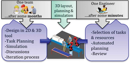
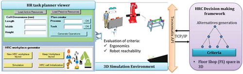
This study deals with the simultaneous HRC workplace design and task planning, comprising the facility layout, the human–robot (HR) task planning and the evaluation of alternative designs. The design of the HRC cell currently asks for considerable time and a working team of engineers, robot specialists, designers, system integrators, etc. The problem was initially addressed by Tsarouchi et al. (Citation2016a). The proposed tool considers a method that integrates the rules and knowledge of the cell design and enables the generation of good quality alternative designs, in a short time frame (). The requirements are defined in order for multiple criteria to be selected.
Figure 1. Problem overview.
The facility layout problem of robots has been investigated by Kusiak and Heragu (Citation1987), Meller and Gau (Citation1996), Drira, Pierreval, and Hajri-Gabouj (Citation2007), Aly, Abbas, and Megahed (Citation2010) and Tubaileh (Citation2014), but the task planning has not been considered in the problem formulation. The optimisation of a robot workcell has been investigated by Tay and Ngoi (Citation1996), while task planning algorithms for multi-agent teams, including both humans and robots have been investigated by Takata and Hirano (Citation2011), Galindo et al. (Citation2008) and Tsarouchi, Makris, and Chryssolouris (Citation2016).
Decision-making frameworks for task planning based on the evaluation of multiple criteria have been proposed by Chryssolouris, (Citation2006), Mourtzis (Citation2005), Sabaei, Erkoyuncu, and Roy (Citation2015) and Tom et al. (Citation2015), but have not been considered in the case of combining humans and robots. A decision-making framework for the sequential human–robot tasks planning was presented by Tsarouchi et al. (Citation2016b), where the layout design was defined. The problem of the robotic line design and the alternative configurations has been investigated by Michalos, Makris, and Mourtzis (Citation2012). In this research effort, the human resources have not been considered. A real-time subtask allocation and scheduling algorithm for hybrid assembly systems have been investigated by Chen et al. (Citation2014) enabling the assembly cost-effectiveness. A model enabling optimal allocation of tasks to multiple human and robot team leaders is described by Malvankar-Mehta and Mehta (Citation2015).
An extended review on the simulation tools and their use in manufacturing has been presented by Mourtzis, Doukas, and Bernidaki (Citation2014), while the role of DHMs has been investigated by Chaffin (Citation2007). The Automatic Path Planning (APP) for robots (Hoshino and Maki Citation2015) has been considered in some open-source tools, such as MoveIt! in Gazebo, VREP, etc., but the majority of the robotics simulation tools (e.g. RoboLogix, LpzRobots, Marilou, Webots, etc.) still lack in the integration of DHMs. There are commercial tools that provide simplified approaches for both robots and humans, APP such as Robcad and Process Simulate by SIEMENS, 3D Automate by Visual Components, DELMIA by Dassault Systèmes, etc. However, efficient methods for the automatic generation of the HRC workcell layouts are still investigated (Tsarouchi et al. Citation2016a).
The research contribution of the proposed approach involves the automatic workcell layout generation and task planning between human and robot resources. Multiple criteria are defined upon the user’s requirements in order to enable the selection of a good result, regarding both the HRC layout and the task planning. Unified modelling of both active and passive resources, allowing teams of humans, robots and humans–robots to be considered for a cooperative task execution, is introduced in this research study. Another advantage is the integration of the decision-making framework with a 3D simulation tool, enabling the calculation of criteria in a simulation mode and the visualisation of the result in a short time frame. In this way, the user is able to validate the proposed result of the layout and check preliminarily the simulation of the HR tasks.
The approach is presented in Section 2, while the implementation of the proposed work is described in Section 3. The case studies description for white goods and automotive industry follow in Section 4. Conclusions and future work follow in Section 5.
2. Approach
A generalised model is proposed for the structuring of the available resources (). The individual resources level consists of the robots and humans (active resources), as well as the fixtures, working tables, etc. (passive resources). Each active resource has attached a tool (e.g. gripper, screw driver, etc.), while each passive resource is considered for the work on a part. The active and passive resources’ parameters such as kinematics, dimensions, etc. are defined within a 3D simulation tool. The tasks are grouped into processes, which constitute the workload (Makris et al. Citation2014).
Figure 2. (a) Resources and (b) human–robot tasks model.
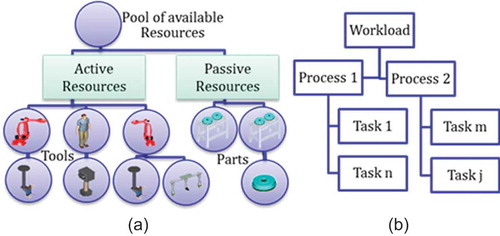
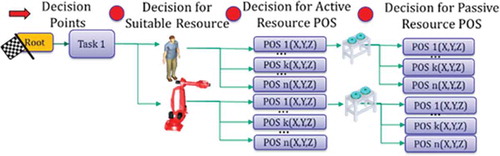
For a given a task (), the decision-making mechanism selects among the suitable active resources (humans or robots). These resources are decided upon the payload, the reachability, the capability of handling equipment and parts, the number of resources required for a task, etc. These parameters are also defined within the 3D simulation environment. Further decisions constitute the position of the active resource(s), the selection of the passive resource and its position in the workcell. In the decision-making mechanism, the interaction between active and passive resources is also defined (e.g. which active resource will work on a passive resource for a given task).
Figure 3. HRC task planner – example.
The proposed mechanism is based on a decision-making concept (). The designer’s input is requested in terms of defining the list of tasks to be performed and the available resources.
Figure 4. Framework overview.
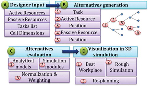
Both analytical models and simulation are used for the estimation of criteria values. These criteria values are decided upon a number of user’s requirements. These requirements include the minimum workspace that is required, the improvement of human ergonomics, the robots’ capabilities to execute a task (in terms of reachability), the minimum total time for the tasks’ execution and the overall cost of the selected resources. The method is quite general and can support any criterion defined upon the different requirements.
Regarding the analytical models, the shop floor space utilisation for every active and passive resource is estimated with Equation (1).
where ximax and yimax are the maximum values of x, y positions for passive and active resources, respectively; and ximin and yimin are the minimum values of x, y positions for passive and active resources, respectively.
The total time to complete human and robot tasks is one more criterion. It is estimated with Equation (2) and should be minimised for the human resources during the evaluation of criteria.
where
is the completion time of a task i that is assigned to a human resource; and n is the total number of tasks that have been assigned to a human resource.
The investment cost criterion (Equation (3)) concerns the cost of the active and passive resource for a workplace layout. The target investment cost should be kept as low as possible.
where
is the cost of active or passive resources;
The reachability criterion of the robot resources is implemented in 3D simulation environment. The result of this criterion is given by the relation in Equation (4).
where WE, the robot’s work envelope, is the range of movement, measured in metres; are the robot’s base frame position on the x, y and z axes, respectively; and
are the part’s mass centre position on the x, y and z axes, respectively.
The simulation tool is also used for the estimation of the criteria values regarding the ergonomics analysis of human tasks. For the ergonomics evaluation, the average human muscles strain (AMS) percentage (%) is estimated during simulation of a task using Equation (5). The method for the estimation of this factor is implemented within the simulation tool and regards the measurements made during the execution of a human task.
where refers to the maximum muscle strain percentage (%) for the human muscles that are involved in a specific task. This value is estimated during a task execution in the 3D simulation environment for each muscle. And n refers to the number of muscles that are involved in a specific task.
Since the earlier criteria are estimated for each alternative solution, the final step is that of the normalisation, weighting and their final ranking (Equations (6)–(8)). The normalisation is performed for the criteria that should be maximised (Equation (6)) or minimised (Equation (7)), while the utility value is calculated as the sum of the normalised criteria values (Cij) multiplied by a weight factor (wc) (Equation (8)). The Cij is the value of alternative i with respect to criterion j.
where Cij is the normalised value of a criterion; Cij is the value of a criterion j for the alternative i; and
are the minimum and maximum values that a criterion j has;
is the weight factor of each criterion. The sum of the weight factors is 1.
Since there is not a specific user’s requirement as to which criterion should have more weight in this framework, the five selected criteria are of the same weight =0.2. The final solution is selected on the basis of maximisation of the utility value, Ui. This solution can be further simulated within the 3D simulation tool and allow the designer to check the initial requirements satisfaction.
3. Implementation
The HRC task planner viewer has been designed and developed based on the existing Tecnomatix libraries. The system architecture () includes communication between the 3D simulation tool and the decision-making mechanism, implemented in JAVA and packaged as a jar file. The communication between the simulation tool and the framework is based on the TCP/IP connection.
Figure 5. Integration architecture.
In the HRC task planner viewer, the user fills the expected cell dimensions and loads the relevant passive and active resources. The list of tasks is also considered as a user-defined input. When the user selects the ‘new HRC workplace layout’ button, the communication with the decision-making mechanism starts. A number of alternatives are selected, visualised, simulated and evaluated. Rough simulation of the HR reachability follows in order to be checked if the active resources have reached the assigned working areas. An ergonomics analysis for the human task is also performed. Evaluation of the criteria and the visualisation of the best alternative follow in a 3D environment.
4. Case studies
The proposed framework has been applied to two different case studies from the white goods and the automotive industries.
4.1. White goods industry case study
This case study concerns the sealing of a refrigerator with the collaboration of human and robot (Michalos et al. Citation2015). The active resources include two robots and two human operators that can cooperate with each other, while the passive resources include a conveyor and a working table. The workload includes two processes and five tasks (). Each task can be assigned to a number of active resources being available.
Figure 6. White goods case – workload and suitable resources.
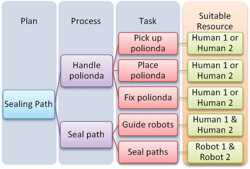
The human assisted by a second operator handles a panel and places it on the refrigerator body. A sealing path is created with the help of two robots, guided by both human operators. For this operation, the user is able to generate a layout and task planning with the help of the proposed tool.
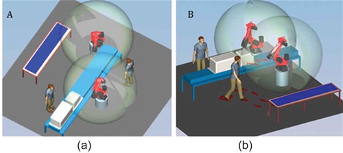
Two alternative solutions () regarding the layout and task planning for the white goods may be generated. The reachability of the robots in the working area and the human path planning, through the different working areas, are also visualised. In scenario ‘a’, the two robots are in a line, while in scenario ‘b’ they are placed opposite to each other. The constraints in the sequence of tasks are not violated and since the reachability criteria are also met, both solutions are feasible.
Figure 7. (a) Layout and task planning alternative – A; (b) final layout and task planning alternative – B.
The scores of the five different criteria of the alternatives are estimated () and the second alternative is selected since it has the maximum utility value (0.85).
Table 1. White goods industry case– criteria scores.
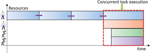
The planning result of the white goods industry is presented in , where both humans and robots share tasks between them within a specific time frame.
Figure 8. White goods industry– HR task planning result.
4.2. Automotive industry case study
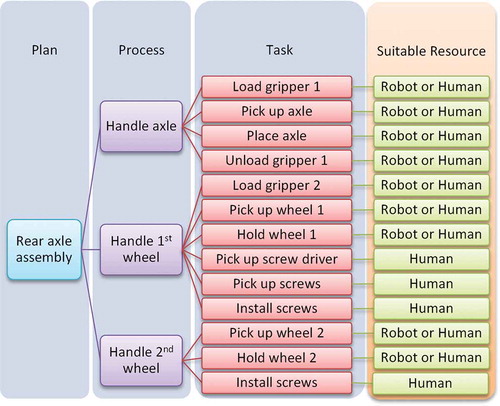
The second case study deals with a vehicle’s rear axle assembly. The active resources comprise one robot and one human operator, while the passive resources are five different working tables and fixtures. The workload of this case study involves three processes and 13 tasks in total ().
Figure 9. Automotive case – workload and suitable resources.
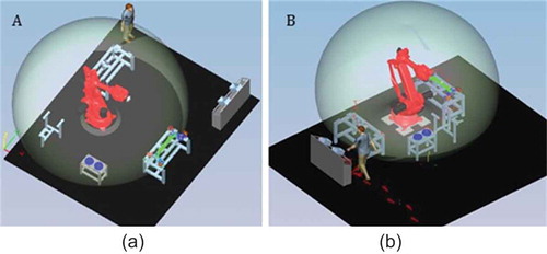
The user follows the same steps as in the first pilot case and the alternative layouts and task plans are generated. Different alternative setups () are evaluated against the selected criteria (). The second alternative is selected as a good solution with maximum utility value 0.81.
Table 2. Automotive industry case – criteria scores.
Figure 10. (a) Layout and task planning alternative – A; (b) final layout and task planning alternative – B.
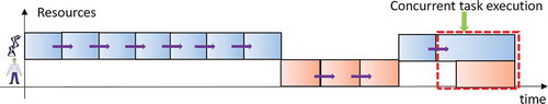
The planning result between the human and robot tasks is visualised in . The last two tasks are executed concurrently, since the human is fixing the wheel on a position and the robot is holding the wheel until it has been completely fixed.
Figure 11. Automotive industry – HR task planning result.
5. Conclusions and future work
This paper is focused on automatically generating an HRC workplace through the allocation of tasks to humans and robots. This tool can be used for the generation of only an HR task planning of a fixed workplace layout. Compared with existing research efforts, this work does not focus on providing a real-time method optimising cost-effectiveness, but rather enabling the automatic design of a hybrid layout and HR task allocation considering multiple criteria.
Both human and robot resources are modelled in a unified approach and can be further used for task allocation and workplace generation. The simulation tools including both humans and robots reduce significantly the time required for the design and simulation of a new cell. Multiple criteria evaluation based on both analytical models and simulation modules have been integrated in the HRC task planner. This enables the integration of new criteria, based on the user requirements and specifications. The proposed method considers multiple criteria for evaluation, while for example in the work by Chen et al. (Citation2014) and Malvankar-Mehta and Mehta (Citation2015), the focus is rather given on maximising the overall system performance and minimising the processing cost and time. Rough simulation of HR tasks for the estimation of both humans’ and robots’ reachability has been considered in this study.
There is still ongoing research on the criteria selection for the design of an HR workcell. Additionally, the automatic generation of multiple resource path plans is also an open research issue that promises reduction in the time required for simulation. The automatic simulation of robot and human paths will also enable the integration of criteria, having to do with the completion of the time to the tasks, the robot speed, the acceleration, etc.
Acknowledgements
This research has been supported by the project ‘ROBO-PARTNER – Seamless Human-Robot Cooperation for Intelligent, Flexible and Safe Operations in the Assembly Factories of the Future’ (Grant Agreement: 608855) (www.robo-partner.eu) funded by the European Commission.
Disclosure statement
No potential conflict of interest was reported by the authors.
Additional information
Funding
References
- Aly, M. F., A. T. Abbas, and S. M. Megahed. 2010. “Robot Workspace Estimation and Base Placement Optimisation Techniques for the Conversion of Conventional Work Cells into Autonomous Flexible Manufacturing Systems.” International Journal of Computer Integrated Manufacturing 23 (12): 1133–1148. doi:10.1080/0951192X.2010.528033.
- Chaffin, D. B. 2007. “Human Motion Simulation for Vehicle and Workplace Design.” Human Factors and Ergonomics in Manufacturing 17 (5): 475–484. doi:10.1002/hfm.20087.
- Chen, F., K. Sekiyama, F. Cannella, and T. Fukuda. 2014. “Optimal Subtask Allocation for Human and Robot Collaboration within Hybrid Assembly System.” IEEE Transactions on Automation Science and Engineering 11 (4): 1065–1074. doi:10.1109/TASE.2013.2274099.
- Chryssolouris, G. 2006. Manufacturing Systems - Theory and Practice. 2nd ed. New York: Springer-Verlag.
- Claes, D., and K. Tuyls. 2015. “Human Robot-Team Interaction Towards the Factory of the Future.” Artificial Life and Intelligent Agents, Communications in Computer and Information Science 61–72. doi:10.1007/978-3-319-18084-7_5.
- Drira, A., H. Pierreval, and S. Hajri-Gabouj. 2007. “Facility Layout Problems: A Survey.” Annual Reviews in Control 31 (2): 255–267. doi:10.1016/j.arcontrol.2007.04.001.
- Galindo, C., J. Fernández-Madrigal, J. González, and A. Saffiotti. 2008. “Robot Task Planning Using Semantic Maps.” Robotics and Autonomous Systems 56 (11): 955–966. doi:10.1016/j.robot.2008.08.007.
- Hoshino, S., and K. Maki. 2015. “Safe and Efficient Motion Planning of Multiple Mobile Robots Based on Artificial Potential for Human Behavior and Robot Congestion.” Advanced Robotics 29 (17): 1095–1109. doi:10.1080/01691864.2015.1033461.
- Krüger, J., T. K. Lien, and A. Verl. 2009. “Cooperation of Human and Machines in Assembly Lines.” CIRP Annals - Manufacturing Technology 58 (2): 628–646. doi:10.1016/j.cirp.2009.09.009.
- Kusiak, A., and S. S. Heragu. 1987. “The Facility Layout Problem.” European Journal of Operational Research 29 (3): 229–251. doi:10.1016/0377-2217(87)90238-4.
- Makris, S., P. Tsarouchi, D. Surdilovic, and J. Krüger. 2014. “Intuitive Dual Arm Robot Programming for Assembly Operations.” CIRP Annals - Manufacturing Technology 63 (1): 13–16. doi:10.1016/j.cirp.2014.03.017.
- Malvankar-Mehta, M. S., and S. S. Mehta. 2015. “Optimal Task Allocation in Multi-Human Multi-Robot Interaction.” Optimization Letters 9: 1787–1803. doi:10.1007/s11590-015-0890-7.
- Meller, R. D., and K. Gau. 1996. “The Facility Layout Problem: Recent and Emerging Trends and Perspectives.” Journal of Manufacturing Systems 15 (5): 351–366. doi:10.1016/0278-6125(96)84198-7.
- Michalos, G., S. Makris, and D. Mourtzis. 2012. “An Intelligent Search Algorithm-Based Method to Derive Assembly Line Design Alternatives.” International Journal of Computer Integrated Manufacturing 25 (3): 211–229. doi:10.1080/0951192X.2011.627949.
- Michalos, G., S. Makris, P. Tsarouchi, T. Guasch, D. Kontovrakis, and G. Chryssolouris. 2015. “Design Considerations for Safe Human-Robot Collaborative Workplaces.” Procedia CIRP 37: 248–253. doi:10.1016/j.procir.2015.08.014.
- Mourtzis, D. 2005. “An Integrated System for Managing Ship Repair Operations.” International Journal of Computer Integrated Manufacturing 18 (8): 721–733. doi:10.1080/09511920500234044.
- Mourtzis, D., M. Doukas, and D. Bernidaki. 2014. “Simulation in Manufacturing: Review and Challenges.” Procedia CIRP 25: 213–229. doi:10.1016/j.procir.2014.10.032.
- Sabaei, D., J. Erkoyuncu, and R. Roy. 2015. “A Review of Multi-Criteria Decision Making Methods for Enhanced Maintenance Delivery.” Procedia CIRP 37: 30–35. doi:10.1016/j.procir.2015.08.086.
- Takata, S., and T. Hirano. 2011. “Human and Robot Allocation Method for Hybrid Assembly Systems.” CIRP Annals - Manufacturing Technology 60 (1): 9–12. doi:10.1016/j.cirp.2011.03.128.
- Tay, M. L., and B. K. A. Ngoi. 1996. “Optimising Robot Workcell Layout.” The International Journal of Advanced Manufacturing Technology 12 (5): 377–385. doi:10.1007/BF01179814.
- Tom, B., S. Neugebauer, S. Schenker, K. Lindow, and R. Stark. 2015. “Multi-Criteria Decision Making as a Tool for Sustainable Product Development – Benefits and Obstacles.” Procedia CIRP 26: 70–75. doi:10.1016/j.procir.2014.07.110.
- Tsarouchi, P., S. Makris, and G. Chryssolouris. 2016. “Human – Robot Interaction Review and Challenges on Task Planning and Programming.” International Journal of Computer Integrated Manufacturing 29 (8): 916–931. doi:10.1080/0951192X.2015.1130251.
- Tsarouchi, P., S. Matthaiakis, S. Makris, and G. Chryssolouris. 2016b. “On a Human-Robot Collaboration in an Assembly Cell.” International Journal of Computer Integrated Manufacturing 1–10. doi:10.1080/0951192X.2016.1187297.
- Tsarouchi, P., J. Spiliotopoulos, G. Michalos, S. Koukas, A. Athanasatos, S. Makris, and G. Chryssolouris. 2016a. “A Decision Making Framework for Human Robot Collaborative Workplace Generation.” Procedia CIRP 44: 228–232. doi:10.1016/j.procir.2016.02.103.
- Tubaileh, A. S. 2014. “Layout of Robot Cells Based on Kinematic Constraints.” International Journal of Computer Integrated Manufacturing 1–13. doi:10.1080/0951192X.2014.961552.