
 ?Mathematical formulae have been encoded as MathML and are displayed in this HTML version using MathJax in order to improve their display. Uncheck the box to turn MathJax off. This feature requires Javascript. Click on a formula to zoom.
ABSTRACT
A methodology for enabling the implementation of the Digital Twins (DTs) of industrial robots and complex machines is presented. The enabled DT can provide a series of benefits, for instance when combined with the degradation curves of critical health indicators can allow predicting the robots’ RUL. This paper suggests a systematic and generic methodology to address challenges such as (1) the definition of the physics-based model parameters for accurate DTs, (2) selection of the parameters to tune and the frequency of their tuning to capture the physical changes in the digital world, (3) calculation of new modeling parameters values based on the collected filed data and their automated propagation to the digital model. A software module to implement these functionalities was developed, whereas the testing and validation of the module were held for an industrial robotic manipulator for a manufacturing application. The results prove that the methodology is generic to accommodate the desired granularity per case, and that the tuning of the digital model ensures realistic DTs, which sets the foundation for physics-based predictive maintenance tools.
1. Introduction
Nowadays, the advancements in sensory technologies and ICT tools have made it possible to collect large volumes of data that contain valuable information about the process and operations executed from industrial equipment. These data are usually gathered by heterogeneous sensors and are then stored in databases enabling post-process analysis, as well as the use of Digital Twins (DT). DT is a new paradigm that emerged complimentarily with the data-driven approaches for data analytics and it can be defined as a system of elements including a physical object, its digital model, and the corresponding data and information flows (Grieves Citation2014). This means that DTs involve the automatic bidirectional exchange of data between the physical and virtual spaces aiming to improve the performance of the physical entity and boost the analysis performance of the virtual counterpart (Lattanzi et al. Citation2021).
Several industrial sectors can benefit from the DT concept (Hlady, Glanzer, and Fugate Citation2018; Kuo et al. Citation2021) with the manufacturing sector being among the most active sectors in DT-related research and development (Errandonea, Beltrán, and Arrizabalaga Citation2020). The importance of the DT concept is also embraced by a series of multinational companies that actively pursue relevant research and applications. For instance, ABB Ability delivers a unified, cross-industry digital capability where devices, systems, solutions, services, and a platform interact optimally together and has embarked on the creation of digital representations of sensors, devices, and systems – a digital twin (ABB Citation2021). Siemens claims that the potential applications for a DT depend on the modeled stage of the product lifecycle and distincts three types of DTs, namely, – Product, Production, and Performance. Finally, Siemens defines the digital thread as the combination and integration of the three digital twins as they evolve together (Siemens Citation2022). GE is also active in the DTs for manufacturing (Electric, General Citation2019).
Popular applications where DT can add value include lifecycle management, traceability of assets, product and layout design, process, logistics, and production optimization, as well as production management and control (Arkouli et al. Citation2021; Michalos et al. Citation2018; Makris Citation2021; Guo et al. Citation2021; Zhuang, Liu, and Xiong Citation2018; Wang et al. Citation2021). Maintenance activities management seems to have aroused the research interest the most (Aivaliotis, Georgoulias, and Chryssolouris Citation2019) in the effort to strengthen the competitive position of industries by increasing the overall plant availability (Chryssolouris Citation2006). The research efforts so far can be classified into three types: 1) frameworks proposed for application, 2) modeling methods and 3) interaction between the physical and virtual entities (You et al. Citation2022).
Modeling is the backbone of Digital twins. The digital model typically contains geometrical information, e.g. the shape of objects, whereas more realistic visualization can be achieved with texture mapping. Geometrical models contain the static information of the system hence simulation techniques are added to represent the operation of the physical entity. Geometrical models are usually imported to physics-based simulations, whose performance depends on the accuracy of the model that is imported into the simulation, as well as the corresponding assumptions (Arkouli, Aivaliotis, and Makris Citation2020). Another category of models is called rule-based and represents the knowledge that derives from historical data and experts about the behavior of the physical assets. Rule-based models are usually extracted by the use of statistical methods and machine learning models, whereas the rules that they use are described with knowledge representation methods such as ontology (You et al. Citation2022).
Physics-based simulations such as Finite Element Methods and Computational Fluid Dynamics are quite popular since the DT concept has emerged from the aeronautics and airspace field (Shafto et al. Citation2010) for understanding the condition of the aircraft and predicting its maintenance needs (Tuegel et al. Citation2011). Analytical and numerical models for multibody mechanical systems (Qiang, Flores, and Lankarani Citation2018) may also be used as the virtual entity of the system. Advanced physics-based models including several physics phenomena have been proposed to exploit the simulation of data to estimate quantities that are of high cost or tough to measure (Aivaliotis et al. Citation2019; Arkouli, Aivaliotis, and Makris Citation2020; Aivaliotis et al. Citation2019). Magargle et al. (Citation2017) combined Modelica models, reduced-order models, as well as controls and sensor models to support the predictive maintenance of automotive braking systems.
Moreover, many modeling methods have been developed to tackle the fault diagnosis and prognosis challenges, which can be categorized as data-driven methods, physical-based methods, and hybrid methods. For instance, finite element models and Monte Carlo methods can provide the probability of crack occurrence (Leser et al. Citation2020). Numerical analysis based on stress data was proposed to analyze the RUL of noise barrier tunnels (Kim and Ah Kim Citation2020). Besides, multi-physical simulations, where the coupling of phenomena e.g. dynamics and thermodynamics are studied for more comprehensive and accurate analyses (Luo et al. Citation2020).
Concerning the data and information flow between the digital and physical entities of a DT, the digital-to-physical connection refers to the transmission of information to the shop floor which is usually provided to support decision-making. Therefore, it is frequent that human-in-the-loop approaches are required. Especially when information on the upcoming defects is accessible, informed decision-making and optimization of the company’s maintenance policy are possible (Aivaliotis, Georgoulias, and Chryssolouris Citation2019). In this perspective, the vision of being able to access information about the real status of the machinery equipment from anywhere is very appealing (Dimitropoulos et al. Citation2020) since it would enable operator support and thus maintainers would be able to execute maintenance activities following the RUL and maintenance plan generated by digital twins.
The majority of the presented research has focused on the physical-to-digital connection, whose objective is to transmit data from the physical world into the virtual environment in real-time. This, in turn, feeds algorithms responsible for the model evolution i.e. the tuning of the digital model’s parameters so that the simulated behavior converges with the actual behavior of the system. Usually, the tuning is performed with iterative simulations that enable the identification of the parameters’ values that approximate the response of the actual system (Kuehn Citation2018). This process generates a large amount of data and information. Hence, the developers should ensure that the data and information generated by the DTs are consistent and synchronized otherwise the effectiveness of the parameters’ identification might be unreliable. In this perspective, the proper information structuring is deemed critical (Ciano et al. Citation2020) to reduce data collection effort same as the consistency and uniqueness of the stored datasets (Negri, Fumagalli, and Macchi Citation2017). ROS-based communication has been used in a DT enabling reconfigurable hybrid shopfloors (Kousi et al. Citation2021). Kousi et al. (Citation2019) worked on the semantics and data synthesis under a unified common environment to realize a DT for the adaptation of robots’ behavior in flexible robotic assembly lines. Thereby it occurs that the infrastructure is a critical aspect to define as it is the foundation of data acquisition and transmission.
Several DT architectures have been proposed over the years integrating different communication protocols, such as OPC UA (Damjanovic-Behrendt and Behrendt Citation2019). Nakagawa et al. (Citation2021) have provided a comprehensive review of reference architectures that can be employed within the industry 4.0 environment and thus, facilitate building effectively more efficient IT infrastructures. For instance, RAMI4.0 and IIRA have been frequently used by researchers for manufacturing applications (Steindl et al. Citation2020). A five-dimensional extension of the model introduced by Grieves (Citation2014) was proposed to enable prognostics (Fei et al. Citation2018). The ‘Digital Twin Shop-floor’ architecture has been proposed by (Tao and Zhang Citation2017) including the physical, and the virtual shop-floor, as well as a service system for the shop-floor, and shop-floor digital twin data. Zhang, Zuo, and Tao (Citation2018) proposed another architecture with similar components for equipment energy consumption management. Furthermore, edge devices have been proposed to leverage decentralized, hierarchical solutions for physical-to-virtual connection, and reduce the amount of transferred data, as shown in (Short and Twiddle Citation2019).
The enabling of DT concept has been treated with a wide range of methodologies, but it remains an ongoing research item. Standardization on the design and implementation of digital twins has produced some results such as ISO 23,247-1:2021 which introduces a framework supporting the digital twins of observable manufacturing elements. However, the multitude of works proposing different frameworks and courses of action for implementation suggests a common architecture for the implementation of the DTs complying with the industrial requirements and needs remains an open issue (Lattanzi et al. Citation2021). The digital twin is still in the infant stage and seldom researchers investigate the complete mechanical equipment and systems. Nevertheless, single-component DT is hard to fulfill real needs in most cases. Some critical challenges that are open include the construction of a multi-component, multi-level model for a complex system, and tackling the coupling mechanism of different components in DT (You et al. Citation2022).
This paper aims to address a number of open issues that were identified in the literature review. Its contribution is 1) to provide a methodology for the tuning of the physical and virtual entities of complex equipment i.e. industrial robots, 2) the definition of the physics-based model, 3) the corresponding software architecture and data flows, 4) the estimation of new modeling parameters values based on the changes in the actual world. The approach has been tested in an industrial manipulator achieving the convergence of the actual to the simulated behavior in a short number of iterations.
The remainder of the paper will present in detail the approach (Section 2). Section 3 is dedicated to the approach’s implementation, while Section 4 presents the case study to which the method for the DT creation and activation was applied. Section 5 discusses the results of the method, and finally Section 6 summarises the paper’s outcomes and shapes the future research activity of the authors.
2. Approach
The proposed approach aims to create digital models of complex machinery, which are made up of several components and elements, as well as enable the Digital Twin implementation. The DTs can be used for the estimation of the equipment’s Remaining Useful Life (RUL), and thus for predictive maintenance applications, as presented in (Aivaliotis et al. Citation2021). This involves the collection of data from sensors, machine controllers, the physics-based simulation of the asset and so forth in order to ensure the accurate prediction of the asset’s behavior. The main steps of this approach are four, namely: i. the model creation, ii. the selection of modeling parameters for tuning, iii. the software architecture and field data collection, as well as the iv. calculation of the new parameters’ values. These steps are analysed in the following sub-sections.
2.1. Model creation
The virtual model of the manufacturing equipment is developed with the aim to provide representative behavioral data of the equipment’s status. This data will enable to perform activities, such as maintenance planning, based on context acquired from the condition of the working equipment. In this view, the digital model of the equipment should be adequately accurate to be trusted by the industry, but at the same time require the minimum possible effort for development, as well as for operation and maintenance. Thereby, a structured method to select the components to model and the level of detail of each component is presented ().
Figure 1. Sub-steps of model creation.
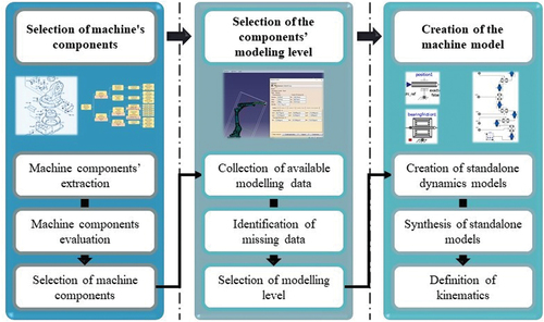
The digital model should incorporate the structural, dynamic, and kinematic characteristics of the equipment. To this end, the person who is responsible for the model creation should identify which components to model. This is addressed by the sub-step ‘Selection of machine’s components’. Initially, a hierarchical analysis of the machinery equipment should be performed, i.e. the machine should be broken down into systems (e.g. electrical, mechanical, etc.), in turn the systems down to their sub-systems (e.g. gearbox), and so forth. This process can be enabled by the producer’s manuals and CAD files. Next, the criticality of each component should be evaluated. The evaluation is based on two criteria: the effect of the components on the health status of the machine and their susceptibility to failures. Historical data of maintenance tasks, existing literature, or even the time-driven maintenance actions which are suggested by the machine’s manufacturer may be used to assess the criticality of the components. Moreover, the experience of the model developer can also be accounted for the assessment. For instance, the user can assess whether a component which does not affect the health status of the equipment needs to be modeled as supporting component. The supporting components are used to provide input for the operation of a critical component for the machine’s health status. Another factor which may influence the selection of the model’s components is the study’s orientation. For instance, this paper is focused on maintenance applications of mechanical components, hence even though other systems (such as fluid system or electrical etc.) may also cause machine failures or underperformance, they will not be considered.
Next, the requirements on the detail level at which each component should be modeled need to be identified. The approach of ‘white box’, ‘grey box’, and ‘black box’ is used in this work similarly to (Aivaliotis et al. Citation2019). The classification of components to the above-mentioned categories is made based on two criteria, which are the available data that can be used for the components model, and the role of the component model in the simulation i.e. if it is of interest to include details about a component in the model. The available modeling data of a component can be structural, kinematic, or dynamic. As for the sources of data they could be manuals of the equipment, product catalogs, CAD files, etc.
With regard to the use of the several modeling levels, ‘White box’ is used when detailed modeling is required (e.g. for a critical machine component) and when there are available data for the detailed modeling. Detailed machine models including only ‘White box’ components is expected to result in more accurate estimations of the machine’s health status. However, due to the lack of modeling data as well as to the requirements for short simulation runtimes and engineering time for the model development the use of restricted models consisting of a mix of ‘white’, ‘black’, and ‘grey’ boxes might be more appropriate to use. ‘black’ boxes are employed for components whose internal operation is not known; ‘grey’ boxes are used when theoretical data (meaning data that can be calculated by using physics-based laws) complement the available modeling data. Modelling data are considered the data that can provide direct assignment of values to the parameters of the equations that are used (i.e. modelling parameters), e.g. the length and intertia of the robot’s links, or enable the estimation of the modelling parameters e.g. the identification of the materials that are in contance enable to identify the corresponding friction coefficients). The model developer should identify whether modeling data are missing and identify a feasible way to collect them such as measurements of the actual equipment and so forth.
When the model developer has identified which components to include in the digital model as well as the level of detail which is required for its component and the data which will be used for the modeling, they should select a software package enabling the required activities. As depicted in this work suggests a modular approach where the digital model development begins with the creation of the standalone digital components. When all the components have been created, they are synthesized to make up the complete digital model based on the available structural and kinematics data. Depending on the software package that is used for modeling the interfacing between the components may require the creation of connection elements or it might be done automatically, the same as the generation of the kinematics relationships. In any case, the integration of the models into one makes up the final digital model.
2.2. Selection of modeling parameters for tuning
Having created the digital model of the asset, the next step is to select the subset of the modeling parameters that will be updated to express the machine’s ongoing condition. To this end, the course of action that is demonstrated in is suggested.
Figure 2. Sub-steps of modeling parameters selection for tuning.
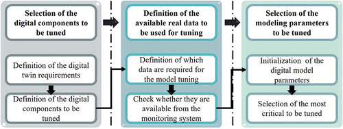
Initially, the method deals with the identification of the requirements for the operation of the Digital Twin. Usually, the main requirement for the DT is to be able to receive data from several data sources on the shop floor and to adjust the behavior of the virtual entity according to the behavior of the real one. It is thus reasonable that among the components that are modeled the selection of those ones to be monitored and updated to capture any changes of the physical world is affected by the available data collection means. The data collection means might be systems measuring data directly from the physical space e.g. machine controllers, integrated sensors, and external sensor systems, but also the virtual sensors that measure data indirectly, where virtual sensors are software modules that are defined within the digital model that is under study. Virtual sensors infere data based on the provided input and calculations that are performed during the simulation in order to estimated data that can be correlated to interpret the status of an actual component. Hence, the capability to install a sensor system to monitor the status of the components, as well as the capability to correlate the status of a component with a virtual sensor can have an impact on the selection of the components to update. Noise, temperature, humidity levels, etc. might undermine the sensor readings, while the limited accessibility of some components might make it impossible to mount a sensor in a convenient area to monitor their operation. Apart from the data availability, the physical phenomena that cause the deterioration of the performance of the machines along with the identification of the components that are more prone to cause machine downtimes are important for the selection of the machine components that should be monitored. If the physical phenomena are too complex the correlation of virtual sensors to the status of the component might be challenging risking the accuracy of the status prediction.
Additionally, it is required to understand which components are critical for the proper operation of the machine and affect its overall behavior. Finally, the modeling detail of the virtual counterparts of the components is important, as the more detailed the model the more comprehensible for its developer to modify its behavior. White box models are easier to tune than black box models in the sense that the impact of the model parameters is explainable and might be more easily understood by the model developer. Given this information, it is possible to identify the specific components to monitor.
For each digital model that will be updated via the tuning algorithm, a particular set of data coming from the real environments should be defined. This data should be capable of reflecting the actual status of the machine and usually come from the machines’ controllers or external sensorial system. Typical paradigms of datasets in manufacturing include pressure, temperature, torques, vibrations, etc. These data should be mapped to the modeling parameters. This might be achieved by either selecting signals that are the parameters of the physics model (direct mapping), or by using physics laws (rigid body dynamics, friction models, D’ Alembert’s principle, etc.). In any case, the measured signals should be associated via some relationship to the parameters of the modelled components.
The final steps of the method include the initialization of the digital model parameters and the selection of the most critical of them to be tuned. The initialization of the model parameters deals with the selecting values for the parameters that represent as well as possible the initial state of the machine. This step includes the model verification and validation processes. In short, the method will ensure that the implemented model accurately represents the model’s conceptual description and its solution. Following, experiments involving the real assets will be run to ensure that the model reflects the operation of the physical asset to an adequate degree. On the one hand, the tuning of the digital model should ensure that the accuracy of the model remains high. The user should select the most critical parameters to be updated by performing sensitivity analyses, as the number of parameters to be tuned impacts the runtime of the tuning algorithm that is responsible to calculate the new parameters’ values. These parameters will be editable and will be considered during the synchronous simulation tuning. Also, some parameters will be tuned with higher frequencies than others because of their greater effect on the simulation results. A weight factor table is employed to define the frequency of tuning for each machine’s component.
2.3. Tuning algorithm
The tuning algorithm () handles the update of the editable modeling parameters in order to match the simulated to the actual asset’s condition. The proposed approach aims to minimize the error between the estimated output and the output that is observed in the system, providing the simulated and the actual systems the same input. Hence, the calculation of the values of the modeling parameters is such that the simulation mirrors the physical asset behavior. More specifically, the common input of simulation (see ) and physical system is ensured by collecting the set of waypoints (position signals) that is about to be executed by the robot and feeding it to the simulation after the required preprocessing of data. Subsequently, after the robot has executed its task, the output data (torque signals) that were produced during the robot’s movement are collected and compared with the output of the simulation. Then, depending on the output error an iterative process may begin with the scope to reduce the output error to an acceptable level by changing the values of the modeling, re-running the simulation, and comparing the new simulation results to the observations from the physical system.
Figure 3. Tuning algorithm.
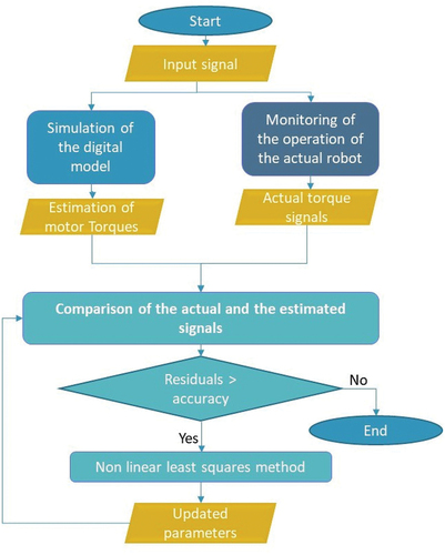
Figure 4. Digital model of the robot manipulator.
In practice, the controller and external sensors are used to collect the necessary data to represent the status of the actual machine, but also the achieved process quality which can help determine whether the behavior of the robot produces acceptable products or not. On the side of the digital model, virtual sensors are used to gather the required data. The data (torque signals) from these two sources are then filtered and structured to be prepared for their comparison. When the output error between the observed and the estimated signals is higher than a predefined threshold equal to the accuracy of the DT, the tuning procedure is triggered.
The method that is suggested in this paper is founded on the work of Aivaliotis et al. (Citation2020). In more detail, the tuning approach is based on the Nonlinear Least Squares method and the target is to approximate the physics-based model of the components with linear ones by iteratively refining the modeling parameters. The decoupling of the axes is addressed via following an acausal and modular modelling approach (as described in the implementation section), where the dynamic problem is decomposed into the robot axes and solved for each robot axis assuming that the influence of the rest of the axes is applied as an additional external load to the axis that is under investigation.
In this method, m number of experimental data are used for the calculation of n independent parameters (where m ≥ n). The model function that is used in this approach connects the required actuating torques for the robot movement with the targeted robot displacement, and it is no other but the digital robot model. The digital robot model receives the target robot trajectories (i.e. a number of joint sets which are to be followed by the robot for the execution of its task) and the modelling parameters values and provides as output the actuating torques of the robot axes, which would be required for executing the target movement. Defining Dr in EquationEquation 2(2)
(2) as the signal from the real environment (actuating torque signals) and Dc EquationEquation 3
(3)
(3) as the estimated by the digital model signal (actuating torque signals), then the torque error vector is ΔD which is the deviation between the physical and virtual signals, as shown in EquationEquation 4.
(4)
(4) The estimation of the modelling parameters is executed minimizing the sum of squares of the residual vector EquationEquation 5.
(5)
(5)
where i represents the time instant, Tact the measured signals from the z components, and Test the estimated signals.
The objective function is shown in (5):
After the modeling parameters are estimated and the model is tuned, the deviation between the actual and digital machine’s component behavior is decreased. When this deviation is lower than the desired limit, the tuning procedure stops, and the new modeling parameters are obtained and propagated to the digital model. The termination condition is defined by the desired accuracy of the estimation using the root mean square residuals to describe the error EquationEquation 5(5)
(5) :
3. System implementation
The implementation of the proposed approach requires software packages that will enable to create the digital model of the assets, to perform the data filtering, structuring, and analysis, as well as their mapping to updates on the model parameters when necessary. The authors implemented their approach using OpenModelica, MATLAB and Python to create the DT of an industrial robot of 6 degrees of freedom. The main criterion for the selection of the software packages was the ease of use, the availability of existing elements ready to be used by the model developer, as well as the availability of ready to use functions, so that the requirements for lower engineering time and modeling effort of the industry are met. In the following sub-sections, the implementation of the approach for the DT creation and the tuning algorithm will be analysed step by step.
3.1. Physics-based model creation
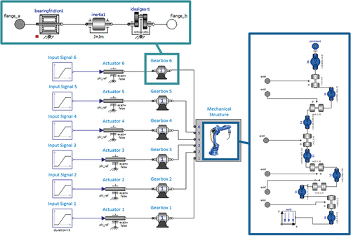
The authors created the robot’s model using OpenModelica, which allows to conveniently model complex heterogeneous physical systems, containing mechanical, electrical, hydraulic, thermal, electric power and other subcomponents (Mattsson, Elmqvist, and Otter Citation1998; Vathoopan et al. Citation2018). Also, OpenModelica allows acausal modeling, i.e. it allows to directly describe the individual parts of the model as hybrid differential algebraic equations. This reduces the number of equations that are needed as opposed to software platforms that use causal approaches (e.g. Simulink) where the systems need to be decomposed into chains of causal interacting blocks described by sets of ordinary differential equations (Dizqah et al. Citation2013). Also, the scaling of multi-physics studying is facilitated via the connector element, which allows easy connection of various domains without needing to clutter in multiple signal ports.
The approach of black, grey and white boxes is implemented by selecting elements of the corresponding modeling detail. For instance, the ‘Input signal’ component is added in place of the combination of a ‘controlBus’ and a ‘PathPlanning’ components, to simplify the input of the reference position signal to the system. On the other hand, the ‘Mechanical structure’ of the robot is critical for the analysis of this work, as it is intended to create a DT for predictive maintenance applications. Thereby, is modelled in detail and it comprises a set of a link and a joint for each one of the robot’s axes, as well as a mass to represent the robot’s payload. The components of the model are described in . This implementation has been proposed in order to facilitate the study of the mechanical system by allowing the modelling of the mechanical parts with higher granularity. However, the proposed implementation is flexible enough to rearrange the focus as per the researcher’s scope by allowing to easily replace the components of the model with other existing ones or custom-made without intense programming effort.
Table 1. Modeling components and modeling level of the robot manipulator.
Each one of the model components is characterized by a set of parameters, which represent the robot’s structural (e.g. the links’ lengths), dynamics (e.g. the motors’ inertias), or kinematic (e.g. the joints’ rotation axes). The values of these parameters depend on the robot which is to be modelled. Therefore, they should be assigned values depending on the case study (e.g. ).
Table 2. Weight factors of robot axes.
3.2. Tuning algorithm
3.2.1. Signal processing and calculations
The implementation of the tuning algorithm requires the collection of the signals (simulation, actual robot), their filtering and structuring so that they are comparable, their comparison, as well as the iterative calculation of new parameters values, when tuning is needed. In this perspective, the authors suggest to use a software package which facilitates signal processing and provides ready to use filtering functions, and/or is easy to use in order to create new functions. MATLAB seems to comply with these requirements. It also provides an appealing plotting environment so that the signals’ deviations are visualized.
3.2.2. Iterative running of simulations and comparison of simulation and field signals
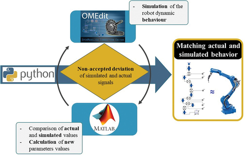
The tuning algorithm comprises the simulation of the model presented in the previous sub-section (OpenModelica), signal processing and calculation of new parameters values which will be performed iteratively. Also, for every new simulation the modeling parameters which were calculated by MATLAB should be propagated to the model of the robot in OpenModelica. For the coordination of the two software packages and the iterative execution of the tuning algorithm, the authors selected Python, as it interfaces with both OpenModelica and MATLAB and it is also a popular language supported by a big community. The combination of the selected software packages is depicted in .
Figure 5. Tuning algorithm implementation-industrial robot.
This study focused on the gearboxes of the robot axes. The modeling of these components involves four parameters: the Coulomb friction torque (Fc), the viscous friction coefficient (Bm), the transmission ratio (ratio) and the inertia of the robot of the motor (Jm). The initial values of the parameters were identified by the manufacturer’s data on the inertia and transmission ratio, as well as with literature data and a series of experiments for the Fc and Bm parameters (Aivaliotis et al. Citation2020).
The selection of the parameters to be tuned was performed based on a short sensitivity analysis and on the expected variation of the parameters with time. More specifically, the transmission ratio and the rotor inertia are not expected to variate with time, therefore they were excluded from the tuning procedure. Thus, the sensitivity analysis was performed to investigate the influence of Bm and Fc on the results of the simulation. There are six sets of Bm and Fc parameters, one for each axis, and one Bm or Fc parameter was examined at a time. The aim of performing the sensitivity analysis was to save computational time by limiting the number of parameters which were tuned in case the effect of some parameters on the simulation was negligible. The results of the sensitivity analysis showed that the effect of the viscous friction coefficient Bm on the simulation’s results, could be considered negligible. Therefore, the 6 Fc parameters (one for each axis) were set as the tuning parameters. A second analysis was performed to identify the frequency of tuning for each robot axis and define the corresponding weight factor. Initially, the tuning algorithm was run for all the parameters to be tuned. The runtime of this tuning procedure was 400 ms. Following, weights were assigned to each axis as shown in and the frequency of update was modified accordingly. The runtime of the tuning procedure was reduced by 30%.
4. Case study
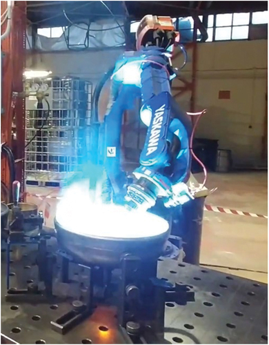
The discussed approach was integrated and tested in a real industrial environment, i.e. a factory producing solar tanks, for a 6 degrees of freedom industrial robot () and aimed to showcase the application of the generic methodology that has been proposed for enabling a predictive maintenance application. This robot is a part of the line to produce water solar tank heaters, and it performs welding tasks for the assembly of the inner solar tank. The quality of the welding seam degrades with time due to the deterioration of the robot’s performance, which for this case study was assumed to derive due to friction effects and wear. The performance of the robot was monitored via proprioceptive sensors including data coming from encoders and motor controllers. In more detail the actuation torques of the driving motors were considered to represent the effort of the robot for the execution of a pre-defined robot trajectory. Any deviation from the nominal torque signal which was corresponding to the executed task (described by a specific set of waypoints – position signals) would indicate some anomaly in the operation of the robot.
Figure 6. Real industrial scenario for the validation of the approach.
The end user’s requirement has been to ensure that the physics-based model of the robot will continuously estimate the behavior of the actual robot with a deviation lower than 5%. This is to enable evaluating the performance of the robot in the current tasks, as well as to estimate what if scenarios for the current status of the robot, for scheduling purposes. Also, is required in order to allow estimating the robot’s future behavior. As presented by Aivaliotis et al. (Citation2021) tuning the virtual model of the robot to mirror the corresponding physical asset in combination with adopting an appropriate prognostic model to adapt the physics-based models parameters accordingly allows estimating the future behavior of the asset.
The tuning algorithm () which ensures the convergence of the actual and the simulated behavior is based on the comparison of the torque signals which are collected from the actual robot and the signals which are estimated by the model. This comparison indicates whether it is of scope to calculate new values for the modeling parameters in order to reduce the deviation of the signals. The new parameters are calculated as indicated in Section 2 and detailed in Section 3.
Figure 7. Tuning algorithm-case study.
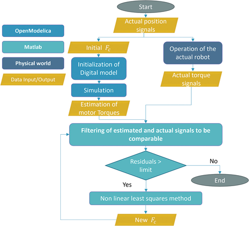
In particular, the tuning algorithm was run as follows. The user-defined position (Actual Position signal), i.e. the robot trajectory for the welding task, was collected from the robot’s controller using ModBus protocol and it was loaded in OpenModelica. The digital model of the robot was simulated in OpenModelica using the modeling parameter values that resulted from the previous tuning procedure. These values of Fc were characterized as initial Fc.
Next, the results of the simulation (Estimated Torque signals) were exported in a MAT-file (which is the data file format that MATLAB uses for saving data to the user’s disk) and along with the signals measured from the robot’s controller (Actual Torque signals) were loaded in MATLAB using the integrated functions for data loading. The torque signals were processed (filtered, scaled, synthesized) in MATLAB in order to be comparable. Following, the torque signals were compared. According to their deviation (residuals), the process followed different courses.
If the residuals were greater than the predefined limit (defined such that the accuracy is greater than 95%), the calculation of new values of Fc started. The new values of Fc depended on the deviation of the Torque signals (meaning that the altering of the parameters values is greater the larger the deviation is) and after the end of the calculation procedure they were inserted in the digital model. The procedure was iterative, and it was based on the approach presented in Section 2. When the termination condition was met, the values of Fc were considered adequate to represent the actual behavior of the robot. In the next tuning procedure, these Fc values were used as the initial Fc. If the deviation between the Actual and the Estimated Torque signals was below the predefined limit, the tuning procedure was not needed.
The parameter function that was used is the robot model which received the estimated parameters of the numerical method and predicted the torques to achieve the user defined trajectory (position input). The model function is nonlinear and it connects the parameters values to the robot torques.
The initial values were defined using data from literature and similar robotic structures (serial manipulators of 6 D.O.F with spherical wrist). The parameter values were changed by an iteration step. The termination condition is defined by the desired accuracy of the estimation, which should be over 95% using the root mean square residuals, EquationEquation 6.(6)
(6)
5. Results
The testing of the proposed methodology was performed for a free space robot motion in a circular trajectory of 40 cm diameter simulating the welding along the circumference of a solar tank (). This trajectory involves all the robot axes. The algorithm was fed with signals which were collected by the robot controller. The signals’ duration was 69 s with a sampling rate of 10 Hz.
The simulation was first performed with the initial parameter values, which were set according to the values found from the literature (Indri et al. Citation2013; Wernholt and Gunnarsson Citation2006; Elhami and David Citation1997). The editable parameters that were tuned were the six Coulomb friction torques (Fc), one for each axis. Following the completion of the simulation, the estimated torque signals were compared to the torque signals collected from the robot’s controller and the values of the parameters were evaluated. According to the evaluation’s results they were considered accurate or they were tuned, as described in Section 2.
depict the iterative procedure that took place for the tuning of the robot’s model. The first iteration resulted in tuning axis 4, while the rest of the axes were deviating more than the acceptable threshold (). Therefore, a new loop was initiated. The weight factors of have been used for the updates of the parameters Fc of the axes. Therefore, the parameters Fc are updated according to the specified frequencies.
Figure 8. Tuning iteration −1.
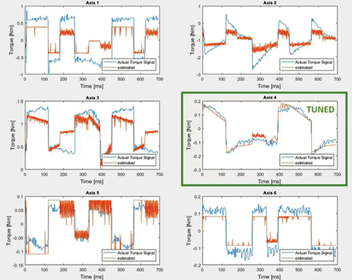
Figure 9. Tuning iteration −2.
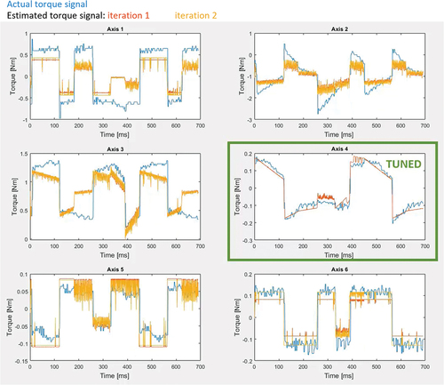
Figure 10. Tuning iteration −3.
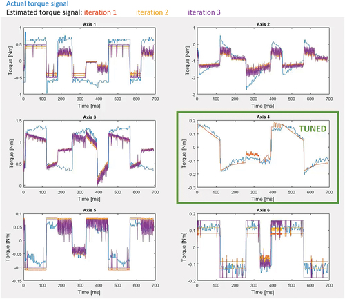
Figure 11. Tuning iteration −4.
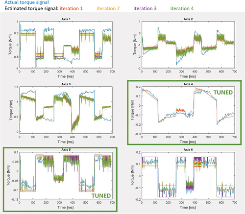
Figure 12. Tuning iteration −5.
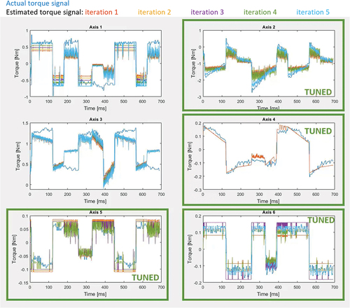
Figure 13. Tuning iteration −6.
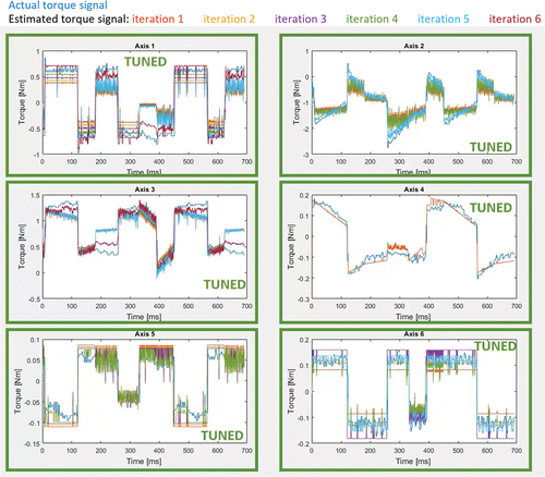
In the second iteration (), the deviations of the axes were improved, however they did not reach the acceptable residuals.
In the third iteration (), the majority of the estimated behaviors have been further improved. In particular, the estimated behavior of axis 6 seems to be worse than the one of the second iterations. This is an expected behavior, as the algorithm that is used for the tuning is set to greatly modify the parameters values when there is risk for chattering in order to avoid unnecessary iterations.
In the fourth iteration () the axis 5 was tuned, while the estimation of the rest of the axes was improved.
In the fifth iteration () axes 2 and 6 were tuned.
Finally, in the sixth iteration () all the axes were tuned.
To sum up, six iterations were needed until the desired deviation was achieved (less than 5%) and the execution of the algorithm for six iterations lasted approximately 6 min.
6. Conclusion and future work
This paper suggested an approach for the enabling and implementation of the DT concept for complex machinery assets including several parts and elements. In particular, it presented a systematic methodology to handle the definition of the physics-based model parameters of the assets so that their update ensures the convergence of the simulated to the actual asset’s behavior. Also, the proposed methodology discussed the selection of the editable parameters of the digital model so that the changes in physical world are properly captured by the digital world. Finally, the calculation of new values for the modeling parameters based on the collected field data and their automated propagation to the digital model has been addressed. The methodology that is suggested is formulated in a generic manner so that the enabling of the digital twin concept for a variety of different machines besides robots be possible. Furthermore, a software module to implement the proposed methodology was developed and implemented for a 6 Degrees of Freedom robot manipulator. The results of this work show that it is feasible to create, implement, and operate a DT with an accuracy of 95%. The work in physics-based robotics Digital Twins is limited, whereas the purpose of the DTs that are available in the literature usually focuses on time aspects, which in turn results in the KPIs that are reported being seldomly comparable to the ones presented in this work, which reveals the need to establish a set of common KPIs in order to facilitate the comparison of different approaches. The presented concept can be utilized for maintenance applications, as it enables to create the digital replicate of the real machine which can be combined with prognostics methods to calculate the RUL of each component of the machine for long-term predictions.
In the future steps, the authors intend to integrate the presented methodology in a generic predictive maintenance framework. The main role of the method will be the assessment of the machines’ condition and the planning of the maintenance activities. The future work also includes the validation of the methodology in a production plant, a replication for a different type of machines e.g. a CNC milling machines, as well as the validation in several industrial sectors. Regarding the effectiveness of the modeling, it is intended to improve the created models in terms of accuracy to eliminate the residuals between the estimated and the real behavior of the assets. The effectiveness of the tuning mechanism will be improved by utilizing a more efficient algorithm to tune the modeling parameters and investigate the performance improvement by reducing the number of the involved software packages. The authors will also investigate the impact of modeling the electrical systems of the robot on the simulation results, as well as on the predicted RUL. Finally, the online execution of the presented concept with real time dataflows and low latency networks will be held in the upcoming works.
Acknowledgements
This research has been supported by the European Institute of Innovation & Technology (EIT) Manufacturing under grant agreement number MOLDAM – Flexible and hybrid robotic manufacturing of composite moulds for large parts in main industrial sectors.
Disclosure statement
The authors have no relevant financial or non-financial interests to declare.
Additional information
Funding
References
- ABB. 2021. ”Model Predictive Control - MPC Technology from ABB - What is New” ABB, https://new.abb.com/industrial-software/features/model-predictive-control-mpc/digital-twin-applications
- Aivaliotis, P., S. Aivaliotis, C. Gkournelos, K. Kokkalis, G. Michalos, and S. Makris. 2019. “Power and Force Limiting on Industrial Robots for Human-Robot Collaboration.” Robotics and Computer-Integrated Manufacturing 59 (October): 346–360. doi:10.1016/j.rcim.2019.05.001.
- Aivaliotis, P., Z. Arkouli, K. Georgoulias, and S. Makris. 2021. “Degradation Curves Integration in Physics-Based Models: Towards the Predictive Maintenance of Industrial Robots.” Robotics and Computer-Integrated Manufacturing 71 (October): 102177. doi:10.1016/j.rcim.2021.102177.
- Aivaliotis, P., K. Georgoulias, Z. Arkouli, and S. Makris. 2019. “Methodology for Enabling Digital Twin Using Advanced Physics-Based Modelling in Predictive Maintenance.” Procedia CIRP 81: 417–422. Elsevier doi:10.1016/j.procir.2019.03.072.
- Aivaliotis, P., K. Georgoulias, and G. Chryssolouris. 2019. “The Use of Digital Twin for Predictive Maintenance in Manufacturing.” International Journal of Computer Integrated Manufacturing 32 (11): 1067–1080. doi:10.1080/0951192X.2019.1686173.
- Aivaliotis, P., E. Papalitsa, G. Michalos, and S. Makris. 2020. “Identification of Dynamic Robot’s Parameters Using Physics-Based Simulation Models for Improving Accuracy.” Procedia CIRP 96: 254–259. Elsevier B.V. doi:10.1016/j.procir.2021.01.083.
- Arkouli, Z., P. Aivaliotis, and S. Makris. 2020. “Towards Accurate Robot Modelling of Flexible Robotic Manipulators.” Procedia CIRP 97: 497–501. Elsevier B.V. doi:10.1016/j.procir.2020.07.009.
- Arkouli, Z., G. Kokotinis, G. Michalos, N. Dimitropoulos, and S. Makris. 2021. “AI-Enhanced Cooperating Robots for Reconfigurable Manufacturing of Large Parts.” IFAC-PapersOnline 54 (1): 617–622. doi:10.1016/J.IFACOL.2021.08.072.
- Chryssolouris, G. 2006. Manufacturing Systems: Theory and Practice. Manufacturing Systems: Theory and Practice. Springer-Verlag. doi:10.1007/0-387-28431-1.
- Ciano, M. P., R. Pozzi, T. Rossi, and F. Strozzi. 2020, December. “Digital Twin-Enabled Smart Industrial Systems: A Bibliometric Review.” International Journal of Computer Integrated Manufacturing 1–19. doi:10.1080/0951192X.2020.1852600.
- Damjanovic-Behrendt, V., and W. Behrendt. 2019. “An Open Source Approach to the Design and Implementation of Digital Twins for Smart Manufacturing.” International Journal of Computer Integrated Manufacturing 32 (4–5): 366–384. doi:10.1080/0951192X.2019.1599436.
- Dimitropoulos, N., T. Togias, G. Michalos, and S. Makris. 2020. “Operator Support in Human-Robot Collaborative Environments Using AI Enhanced Wearable Devices.” Procedia CIRP 97: 464–469. Elsevier. doi:10.1016/j.procir.2020.07.006.
- Dizqah, A. M., A. Maheri, K. Busawon, and P. Fritzson. 2013. “Acausal Modelling and Dynamic Simulation of the Standalone Wind-Solar Plant Using Modelica.” Proceedings - UKSim 15th International Conference on Computer Modelling and Simulation, UKSim, 2013, 580–585. 10.1109/UKSIM.2013.145
- Electric, General. 2019. “Digital Twins are Mission Critical” https://www.ge.com/digital/applications/digital-twin
- Elhami, M. R., and J. B. David. 1997. “Sequential Identification of Coulomb and Viscous Friction in Robot Drives.” Automatica 33 (3): 393–401. doi:10.1016/S0005-1098(96)00183-5.
- Errandonea, I., S. Beltrán, and S. Arrizabalaga. 2020. “Digital Twin for Maintenance: A Literature Review.” Computers in Industry 123. doi:10.1016/j.compind.2020.103316.
- Fei, T., M. Zhang, Y. Liu, and A. Y. C. Nee. 2018. “Digital Twin Driven Prognostics and Health Management for Complex Equipment.” CIRP Annals 67 (1): 169–172. doi:10.1016/j.cirp.2018.04.055.
- Grieves, M. 2014. “Digital Twin: Manufacturing Excellence Through Virtual Factory Replication.” White Paper.
- Guo, H., Y. Zhu, Y. Zhang, Y. Ren, M. Chen, and R. Zhang. 2021. “A Digital Twin-Based Layout Optimization Method for Discrete Manufacturing Workshop.” International Journal of Advanced Manufacturing Technology 112 (5): 1307–1318. doi:10.1007/s00170-020-06568-0.
- Hlady, J., M. Glanzer, and L. Fugate. 2018. “Automated Creation of the Pipeline Digital Twin During Construction - Improvement to Construction Quality and Pipeline Integrity.” Proceedings of the Biennial International Pipeline Conference, IPC, 2: 1–12. 10.1115/IPC2018-78146.
- Indri, M., I. Lazzero, A. Antoniazza, and A. M. Bottero. 2013. “Friction Modeling and Identification for Industrial Manipulators.” In IEEE International Conference on Emerging Technologies and Factory Automation, ETFA, 10.1109/ETFA.2013.6647958.
- Kim, J., and S. Ah Kim. 2020. “Lifespan Prediction Technique for Digital Twin-Based Noise Barrier Tunnels.” Sustainability 2020 12 (7): 2940. doi:10.3390/SU12072940.
- Kousi, N., C. Gkournelos, S. Aivaliotis, C. Giannoulis, G. Michalos, and S. Makris. 2019. “Digital Twin for Adaptation of Robots’ Behavior in Flexible Robotic Assembly Lines.” Procedia Manufacturing 28: 121–126. Elsevier B.V doi:10.1016/j.promfg.2018.12.020.
- Kousi, N., C. Gkournelos, S. Aivaliotis, K. Lotsaris, A. Christos Bavelos, P. Baris, G. Michalos, and S. Makris. 2021. “Digital Twin for Designing and Reconfiguring Human–Robot Collaborative Assembly Lines.” Applied Sciences 2021 11 (10): 4620. doi:10.3390/APP11104620.
- Kuehn, W. 2018. “Digital Twins for Decision Making in Complex Production and Logistic Enterprises.” International Journal of Design & Nature and Ecodynamics 13 (3): 260–271. doi:10.2495/DNE-V13-N3-260-271.
- Kuo, Y. H., F. Pilati, Q. Ting, and G. Q. Huang. 2021. “Digital Twin-Enabled Smart Industrial Systems: Recent Developments and Future Perspectives.” International Journal of Computer Integrated Manufacturing 34 (7–8): 685–689. doi:10.1080/0951192X.2021.1959710.
- Lattanzi, L., R. Raffaeli, M. Peruzzini, and M. Pellicciari. 2021. “Digital Twin for Smart Manufacturing: A Review of Concepts towards a Practical Industrial Implementation.” International Journal of Computer Integrated Manufacturing 00 (00): 1–31. doi:10.1080/0951192x.2021.1911003.
- Leser, P. E., J. E. Warner, W. P. Leser, G. F. Bomarito, J. A. Newman, and J. D. Hochhalter. 2020. “A Digital Twin Feasibility Study (Part II): Non-Deterministic Predictions of Fatigue Life Using in-Situ Diagnostics and Prognostics.” Engineering fracture mechanics 229 (April): 106903. doi:10.1016/J.ENGFRACMECH.2020.106903.
- Luo, W., H. Tianliang, Y. Yingxin, C. Zhang, and Y. Wei. 2020. “A Hybrid Predictive Maintenance Approach for CNC Machine Tool Driven by Digital Twin.” Robotics and computer-integrated manufacturing 65 (March): 101974. doi:10.1016/j.rcim.2020.101974.
- Magargle, R., L. Johnson, P. Mandloi, P. Davoudabadi, O. Kesarkar, S. Krishnaswamy, J. Batteh, and A. Pitchaikani. 2017. “A Simulation-Based Digital Twin for Model-Driven Health Monitoring and Predictive Maintenance of an Automotive Braking System.” In Proceedings of the 12th International Modelica Conference, Prague, Czech Republic, May 15-17, 2017, 132:35–46. 10.3384/ecp1713235.
- Makris, S. 2021. Cooperating Robots for Flexible Manufacturing. http://link.springer.com/10.1007/978-3-030-51591-1
- Mattsson, S. E., H. Elmqvist, and M. Otter. 1998. “Physical System Modeling with Modelica.” Control engineering practice 6: 501–510. Pergamon. doi:10.1016/S0967-0661(98)00047-1.
- Michalos, G., A. Karvouniari, N. Dimitropoulos, T. Togias, and S. Makris. 2018. “Workplace Analysis and Design Using Virtual Reality Techniques.” CIRP Annals 67 (1): 141–144. doi:10.1016/j.cirp.2018.04.120.
- Nakagawa, E. Y., P. Oliveira Antonino, F. Schnicke, R. Capilla, T. Kuhn, and P. Liggesmeyer. 2021. “Industry 4.0 Reference Architectures: State of the Art and Future Trends.” Computers & Industrial Engineering 156 (June): 107241. doi:10.1016/j.cie.2021.107241.
- Negri, E., L. Fumagalli, and M. Macchi. 2017. “A Review of the Roles of Digital Twin in CPS-Based Production Systems.” Procedia Manufacturing 11 (June): 939–948. doi:10.1016/j.promfg.2017.07.198.
- Qiang, T., P. Flores, and H. M. Lankarani. 2018. “A Comprehensive Survey of the Analytical, Numerical and Experimental Methodologies for Dynamics of Multibody Mechanical Systems with Clearance or Imperfect Joints.” Mechanism and Machine Theory 122: 1–57. doi:10.1016/j.mechmachtheory.2017.12.002.
- Shafto, M., M. Conroy, and R. Doyle, Glaessgen, C. Kemp, J. Lemoigne, and L. Wang. edited by. 2010. ”DRAFT Modeling, Simulation, Information - Technology and Processing Roadmap.” Technology AreaVol. 11. https://www.nasa.gov/pdf/501321main_TA11-MSITP-DRAFT-Nov2010-A1.pdf.
- Short, M., and J. Twiddle. 2019. “An Industrial Digitalization Platform for Condition Monitoring and Predictive Maintenance of Pumping Equipment.” Sensors 19 (17): 3781. doi:10.3390/S19173781.
- Siemens. 2022. “Digital Twin | Siemens Software.”|“Digital Twin | Siemens Software” https://www.plm.automation.siemens.com/global/en/our-story/glossary/digital-twin/24465
- Steindl, G., M. Stagl, L. Kasper, W. Kastner, and R. Hofmann. 2020. “Generic Digital Twin Architecture for Industrial Energy Systems.” Applied Sciences 10 (24): 8903. doi:10.3390/APP10248903.
- Tao, F., and M. Zhang. 2017. “Digital Twin Shop-Floor: A New Shop-Floor Paradigm Towards Smart Manufacturing.” IEEE Access 5 (September): 20418–20427. doi:10.1109/ACCESS.2017.2756069.
- Tuegel, E. J., A. R. Ingraffea, T. G. Eason, and S. Michael Spottswood. 2011. “Reengineering Aircraft Structural Life Prediction Using a Digital Twin.” International Journal of Aerospace Engineering 2011: 1–14. doi:10.1155/2011/154798.
- Vathoopan, M., M. Johny, A. Zoitl, and A. Knoll. 2018. “Modular Fault Ascription and Corrective Maintenance Using a Digital Twin.” IFAC-PapersOnLine 51 (11): 1041–1046. doi:10.1016/j.ifacol.2018.08.470.
- Wang, Y., W. Ren, L. Yan, and C. Zhang. 2021. “Complex Product Manufacturing and Operation and Maintenance Integration Based on Digital Twin.” International journal of advanced manufacturing technology 117 (1–2): 361–381. doi:10.1007/s00170-021-07350-6.
- Wernholt, E., and S. Gunnarsson. 2006. “Nonlinear identification of a physically parameterized robot model 1.” IFAC Proceedings Volumes 39 (1): 143–148. doi:10.3182/20060329-3-au-2901.00016.
- You, Y., C. Chen, F. Hu, Y. Liu, and Z. Ji. 2022. “Advances of Digital Twins for Predictive Maintenance.” Procedia computer science 200 (January): 1471–1480. doi:10.1016/J.PROCS.2022.01.348.
- Zhang, M., Y. Zuo, and F. Tao. 2018. “Equipment Energy Consumption Management in Applications.” 2018 IEEE 15th International Conference on Networking, Sensing and Control (ICNSC), Zhuhai, China, 1–5.
- Zhuang, C., J. Liu, and H. Xiong. 2018. “Digital Twin-Based Smart Production Management and Control Framework for the Complex Product Assembly Shop-Floor.” International journal of advanced manufacturing technology 96 (1): 1149–1163. doi:10.1007/S00170-018-1617-6.