 ?Mathematical formulae have been encoded as MathML and are displayed in this HTML version using MathJax in order to improve their display. Uncheck the box to turn MathJax off. This feature requires Javascript. Click on a formula to zoom.
ABSTRACT
In this paper, an approach for computing online safety zones for collaborative robotics in a robust way, despite uncertain robot dynamics, is proposed. The strategy implements the speed and separation monitoring paradigm, and considers human and robot enclosed in bounding volumes. The human-robot collaboration is monitored by a supervisory controller that guides the robot to stop along a path-consistent trajectory in case of collision danger between human and robot. The size of the robot safety zone is minimized online according to the stop time of the manipulator, and the uncertain robot dynamics is considered using interval arithmetic to ensure compliance with the joint torques limits even in case of imperfect knowledge of the dynamic model parameters. The results verify the effectiveness of the proposed approach, and evaluate the influence of dynamics variations on human-robot collaboration.
1. Introduction
Collaborative robotics is becoming one of the enabling technologies of modern manufacturing industries. Removing barriers between human and robot paves the way for flexible and human-centered automation in manufacturing. However, ensuring safety in human-robot collaboration is crucial due to possible and not-functional collisions between human and robot during the operation in a shared workspace (Gualtieri, Rauch, and Vidoni Citation2022; Seriani et al. Citation2018). A recent survey that discusses safety technology and standardization according to the principles of risk estimation and the typical strategies for risk reduction in collaborative robotics applications can be found in (Vicentini Citation2021).
The speed and separation monitoring (SSM) is one of the four scenarios described by the ISO/TS 15,066 to achieve safe collaboration between human and robot (ISO Citation2016). The SSM reports that the robot system and the operator are allowed to move concurrently in the collaborative workspace provided that a protective separation distance between operator and robot is ensured at all times.
Several strategies for collision avoidance have been developed in previous literature (Choi et al. Citation2017; Kaltsoukalas, Makris, and Chryssolouris Citation2015; Lin and Saripalli Citation2017). The authors in (Byner, Matthias, and Ding Citation2019) consider both the separation distance and the direction of motion to improve efficiency and productivity in SSM-type applications. An online collision-avoidance approach is developed in (Safeea, Neto, and Bearee Citation2019), where the off-line generated desired path of the manipulator is changed on-the-fly to avoid potential collisions with the body of the human operator, while being able to complete the assigned industrial task. Alternative paths together with a kinematic scaling algorithm are considered in (Zanchettin et al. Citation2019) by a collision-avoidance strategy to enhance the performance of the robot in terms of productivity and cycle time. In (Kim et al. Citation2021), the potential runaway motion of the robot and its maximum permissible speed are investigated to design a safe SSM function. Moreover, in (Palleschi et al. Citation2021) the safety of time-optimal trajectories are evaluated iteratively to plan safe motions along specified paths in shared workspaces.
In (Grushko et al. Citation2021), the robot is able to redesign the nominal motion to avoid collisions with the human operator, which is equipped with an hand-worn haptic feedback device to improve the mutual perception during human – robot collaboration. Furthermore, an elastic band algorithm for collision avoidance is implemented in (Kot et al. Citation2022) to dynamically modify the position of control points on the robot path in reaction to any obstacles located or moving in the workspace. The authors in (Secil and Ozkan Citation2022) represent human and robot as static capsules and adopt the Gilbert-Johnson-Keerthi algorithm to compute the distance between the human and the manipulator in real time. A computationally efficient control scheme for safe human – robot interaction is presented in (Merckaert et al. Citation2022), which relies on the explicit reference governor formalism to enforce input and state constraints in real-time. That method also considers the joint space dynamic model of the robot and the actuator saturation.
The authors in Scalera, Vidoni, and Giusti (Citation2021) and Scalera et al. (Citation2022a) adopt dynamically scaled safety zones as sphere swept lines (SSLs) to verify potential collisions between human and robot. The size of the safety zones enclosing the robot changes during the motion of the manipulator according to its potential stop time, which is minimized online, taking into account the robot dynamics and its joint torque constraints. The manipulator is guided to stop along a trajectory that is planned considering the minimum stop time, but that does not preserve the geometrical path. Furthermore, an approach for planning path-consistent stop trajectories online is presented in (Scalera et al. Citation2022b), showing its benefits in terms of fluency metrics, e.g. the total task time, with respect to the previous strategy.
However, the aforementioned works do not consider uncertainties or inaccuracies in the dynamic model of the manipulator. In these cases, the imperfect knowledge of the dynamics parameters can possibly cause a violation of the joint torque limits during a stop trajectory, when the dynamic model is considered to optimize online such stop trajectory of the robot during a collaborative task. In this work, uncertain robot dynamics is considered using a recursive Newton-Euler (NE) algorithm based on interval arithmetic (Moore, Baker Kearfott, and Cloud Citation2009). These techniques allow for an efficient numerical computation of operations where the variables are subject to bounded uncertainties. In the case of recursive NE algorithms, interval arithmetic can be used to compute over-approximate sets of robot torques/forces from the uncertain model parameters, while keeping the same (linear) computational complexity with respect to the number of degrees of freedom, compared to the classical recursive NE (Giusti and Nainer Citation2022).
The main contribution of this work is the computation of safety zones for collaborative robotics in a robust way, despite uncertain robot dynamics. The strategy implements the SSM paradigm, and considers human and robot enclosed in bounding volumes. The human-robot collaboration is monitored by a supervisory controller that guides the manipulator to stop along a path-consistent trajectory in case of collision danger. The size of the robot safety zone is minimized online according to the stop time of the manipulator, and the uncertain robot dynamics is considered using interval arithmetic to ensure compliance with the joint torques limits even in case of imperfect knowledge of the dynamic model parameters. To the best of the authors’ knowledge, this is the first time that the uncertain robot dynamics is considered for dynamic safety zones in collaborative robotics together with trajectory scaling. The effectiveness of the proposed solution is verified on a model of the Franka Emika Panda arm, a commercial manipulator with 7 degrees of freedom (DOF). The results verify the effectiveness of the proposed approach and shed light on the influence of dynamics variations on human-robot collaboration.
The paper is organized as follows: Section 2 describes the problem statement. The proposed approach is detailed in Section 3, where the strategy for achieving path consistency during the stop, the handling of robot dynamics uncertainty, and the optimization of the size of the robust safety zones are presented. Section 4 illustrates the simulation results. More in detail, the robustness of the proposed approach is verified, and the influence of dynamics uncertainties on human-robot collaboration is analyzed. Finally, the conclusions and the future perspectives are given in Section 5.
2. Problem statement
In this work, a rigid robot manipulator composed of links that performs a collaborative task alongside a human operator is considered. The dynamics parameters of the manipulator (mass
, center of mass
, inertia matrix
) are uncertain within known bounds. The overall model of the manipulator dynamics can be expressed as (Siciliano et al. Citation2010)
where is the vector of the joint states,
is the inertia matrix,
,
, and
, are the centrifugal and Coriolis, friction, and gravity vector terms, respectively. The terms
and
are the control input torque, and the disturbances, respectively. The set of robot parameters is represented by
.
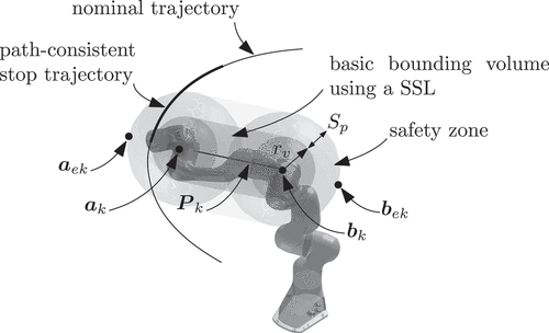
To avoid collisions between the human operator and the robot in motion, a supervisory controller continuously checks the compliance with the SSM function provided in (ISO Citation2016). More in detail, the collision danger between bounding volumes surrounding the human and the manipulator is verified online, and a stop trajectory that complies with the geometrical path is engaged in case a potential risk is identified. The bounding volumes are shaped as SSLs, i.e. the geometrical Minkowski addition of a line segment and a sphere. The reader may refer to for a visualization of the SSL for the k-th link of the robot: the points and
identify the line segment
, whereas
is the radius of the sphere that tightly over-approximates the link geometry.
Figure 1. Representation of a SSL and the corresponding safety zone enclosing one link of the considered manipulator. The path-consistent stop trajectory of the end-effector is shown with a thicker line with respect to the nominal trajectory.
Safety zones are considered as SSL that account for the protective separation distance . The radius
of the safety zone enclosing the k-th link can be defined, according to (ISO Citation2016), as the sum of
and the protective separation distance
to be kept during the collaborative operation.
is computed as follows:
where is the space covered by the manipulator at speed
during the reaction time
, i.e., from the current time
at which the safety check starts to
. On the other hand, the term
represents the space traveled by the robot at speed
during the stop time
.
is the distance covered by the human at the considered worst-case speed (
) during
. Finally,
accounts for multiple error sources in the perception and measurement systems.
To verify a potential collision, the minimum distance between each couple of line segments belonging to the human and the manipulator is computed as in (Ericson Citation2004). Compliance with the SSM paradigm is provided if the manipulator is stopped, or when
, being
the radius of the human bounding volume corresponding to the minimum-distance vector.
To summarize, the objective of this work is to define a collision avoidance approach based on online computed safety zones, which are robust with respect to uncertain robot dynamics. The size of the safety zones is computed online, and a path consistent stop trajectory is engaged by the robot in case of potential collision between the bounding volumes surrounding the human and those enclosing the manipulator. As described in Sect. 3, in this work an efficient and robust strategy is introduced to minimize the stop time of the robot, and in turn the radii of its safety zones, based on the calculation of robot dynamics in case of uncertain parameters.
3. Proposed approach
In this section, the approach proposed in this paper is described. First, the strategy for achieving path consistency during the stop is introduced. Then, the method for dealing with robot dynamics uncertainty is presented. Finally, the optimization of the size of the robust safety zones enclosing the robot is detailed.
3.1. Achieving path consistency during the stop
The nominal trajectory of the robot is defined as a joint space curve , where
is a time-dependent parameter assumed to be twice differentiable. Being
the final time of the desired trajectory, the nominal timing law can be described as
. When a potential collision is identified by the supervisory controller, that parametrization is changed online to plan the stop trajectory
, switching to a five-degree polynomial
. The six coefficients of
are determined by applying the following conditions that ensure continuity with
up to acceleration, and a smooth stop at time
:
The value of is left free to analytically determine the final joint position
, which only depends on the stop time
. A lower degree polynomial can also be considered, e.g. a fourth degree, renouncing to the possibility to set a constraint for the jerk to be equal to zero at the stop time
. However, smoother trajectories have been chosen, since they are considered beneficial for human-robot collaboration settings (Lagomarsino et al. Citation2022). In summary, the formulation of the path-consistent stop trajectory
is expressed by:
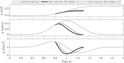
An example of nominal and path consistent stop trajectory (with five and four-degree parameterization) is reported in , which shows the joint position, velocity and acceleration over time. Alternative approaches for the planning of trajectories consistent with the geometrical path are also possible, as for instance those described in (Faroni et al. Citation2021; Lange and Albu-Schäffer Citation2015; Rojas, Giusti, and Vidoni Citation2022; Trigatti et al. Citation2018).
3.2. Handling robot dynamics uncertainty
Interval arithmetic techniques are used to obtain bounded solutions from mathematical operations involving uncertain variables for the robot dynamics computations online. A multidimensional interval is used to describe an uncertain, but bounded, variable:
where and
indicate the infimum and supremum of the interval, respectively. Any operation involving interval variables is performed by its corresponding interval arithmetic operation, allowing for an efficient propagation of the uncertainty. For additional details, the reader may refer to (Althoff and Grebenyuk Citation2016; Moore, Baker Kearfott, and Cloud Citation2009).
Under the assumption of uncertain dynamics parameters (, the robot dynamics can be computed via an interval arithmetic-based NE algorithm (IA-RNEA) (Giusti and Nainer Citation2022)
In particular, given that the standard recursive NE algorithm is indicated with RNEA, the IA-RNEA provides:
Such algorithm yields a lower and upper range of the robot torques given the parameter uncertainty bounds, while maintaining a linear computational complexity with respect to the number of robot DOFs, as the classic NE approach. The IA-RNEA method can be extended in order to include also uncertain kinematics states of the robot base (Giusti and Nainer Citation2022).
3.3. Optimizing the size of the robust safety zones
The idea behind the considered collision avoidance approach is to minimize online the size of the manipulator safety zones, by defining the minimum stop time that satisfies the actuators torque limits during the stop trajectory. Considering
and
as weighting factors, the value of
is determined by solving on-the-fly the following optimization problem:
subject to
where is the value of the stop time at the previous safety check (
at the beginning, where
is the worst-case stop time). The interval torque vector
during
is computed by evaluating the inverse dynamics of the robot considering uncertainties in the dynamics parameters via interval arithmetic.
After the definition of the stop time , the computation of the contribution
to the radius of the k-th dynamic safety zone of the robot in (2) is achieved by considering the velocities of the extreme points
and
of the spherical heads of the safety zone, which are depicted in . To account for the direction of the motion of the robot with respect to the human, only the velocity component directed on the minimum-distance line segment
with respect to the human is considered, as in (Scalera et al. Citation2022a). In this way, the maximum linear velocity
of the k-th safety zone in the direction of
during the path-consistent trajectory that steers the robot to stop is defined as:
A complete description of the method for the calculation of the maximum linear velocities of the safety zones can be found in (Scalera et al. Citation2022a; Scalera, Vidoni, and Giusti Citation2021). With respect to those works, in this paper the computation of uncertain dynamics based on interval arithmetic is introduced to guarantee compliance with the actuators torque limits during stop trajectories even in case of inaccuracies or uncertainties in the dynamic model of the manipulator.
The only requirements needed to implement the proposed solution for a new robot arm are the nominal kinematics and dynamics parameters of the robot as well as the expected bounded uncertainties of the dynamics parameters. The former can be obtained either from CAD or kinematic calibration. The latter can be gathered from measures or estimates (see e.g. the work in (Giusti, Liu, and Althoff Citation2021), which uses reachset conformance testing (Roehm et al. Citation2019) to estimate the bounds of uncertainties of dynamics parameters). Kinematics uncertainties are not considered in this work. The robot is assumed to be calibrated from the kinematics point of view, and that its kinematics parameters do not change after the robot calibration and deployment in operation. In this work, the focus is on the variability of dynamics effects, which are relevant realistic scenarios where the robot is subjected to uncertain payload.
To implement the proposed approach in a real scenario, the robot must be able to accept a desired trajectory profile in position, speed and acceleration, as well as to provide measurements of joints position, velocity and torque. Furthermore, a tracking system must be available to supervise the position of the human operator in real time. The human tracking uncertainties are considered to be bounded, so that they can be included in the term of the protective separation distance in (2).
4. Numerical results
In this section, simulation results are discussed that verify the feasibility of the proposed approach to compute online torque sets to be used to minimize the stop time of path-consistent trajectories. The simulated test bed is first described. Then, the robustness of the proposed approach is verified with extensive simulations in which the results obtained with the IA-RNEA algorithm are compared with those obtained with a classical NE approach, which does not guarantee the satisfaction of torque constraints during a safety stop under uncertain robot dynamics. Finally, the influence of uncertainties on fluency metrics for human-robot collaboration is analyzed by varying the maximum range of the payload applied to the robot end-effector.
4.1. Simulated test bed
The considered simulated test bed includes a Franka Emika Panda arm with 7-DOF. The nominal model dynamical parameters of this manipulator are taken from (Franka Emika Citation2022), and are reported in Appendix A. However, in the case of uncertain parameters, bounds of ,
,
for the center of mass, masses/inertia, and joint viscous and Coulomb friction coefficients, respectively, are considered, as in (Giusti and Nainer Citation2022).
The numerical simulations are implemented exploiting MatlabTM/Simulink® on a computer running Windows 10 Pro with an Intel i7-8565 U CPU and 16 GB of RAM. To solve the minimization problem of the stop time online the sequential quadratic programming iterative method for constrained nonlinear optimization is used. The number of iterations of the algorithm is limited to 10, the rate of the robot tracking controller is set to , and the rate of the supervisory controller to
.
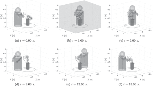
To verify the proposed approach in challenging conditions for the robot, extensive simulations are considered in which the manipulator tracks random trajectories in the joint space, whereas a simulated human cyclically intrudes in the robot workspace, so as to induce safety stops of the robot. A representation of the simulated test bed is shown in , where six frames of an example simulation are shown.
Figure 3. Frames of an example simulation in which the manipulator performs a random trajectory, while the human cyclically enters the robot workspace. A safety stop of the robot is highlighted with grey background.
To define each nominal trajectory, five arbitrary points are selected in the joint space of the robot and are connected in pairs by five-degree polynomials with a time duration of . These polynomial trajectories verify the kinematic and dynamic constraints of the robot. Each nominal trajectory has a duration of
, without considering potential stops and restarts of the robot due to the intrusion of the human.
To simulate the human operator working side-by-side with the robot, a kinematic tree is designed with a head, a chest and two arms, enclosed in six bounding volumes, in a way similar to (Pereira and Althoff Citation2017). During the simulations, the human moves back and forth on a linear path long, positioned at a distance of
from the reference frame of the robot base. A rotation of
along its vertical axis is performed by the human every time it reaches one end of its path. The human does not react to the robot, and its movement is only intended to induce random safety stops of the manipulator using a repeatable and well-known motion pattern. To stress the evaluation of the method in challenging conditions, the human motion law is defined as a trapezoidal speed profile with a speed of
, in accordance with the technical specification (ISO Citation2016). One cycle of the human on its path lasts
. However, the simulated human repeats its path until the manipulator has not completed the whole nominal trajectory.
4.2. Verification of the robustness of the proposed approach
To verify the robustness of the proposed approach, 100 numerical simulations are run for each of the two following cases:
Case (1): the dynamics parameters of the robot are considered uncertain and the payload of the manipulator varies randomly between the bounds of
and
;
Case (2): the dynamics parameters of the robot do not account for uncertainties and for possible payload.
The simulated scenario can be representative of a situation in which the robot performs manipulations or pick-and-place tasks of objects whose weight is not known a priori. Indeed, picking objects of unknown characteristics whose payload is uncertain is a common task in manufacturing, e.g. in bin-picking of diverse objects, sorting and grasping applications, as well as in the packaging of mixed products. In these cases, the uncertain payload introduces uncertainties in the robot dynamics.
In Case (1), the dynamics of the manipulators are evaluated with an IA-RNEA approach to obtain a feasible set of torques for each joint of the robot. On the other hand, Case (2) represents the nominal case, in which no errors in the dynamics parameters are present. In that case, only a single value of nominal torque is computed for each joint of the robot.
Once the simulations are run, the position , velocity
, and acceleration
of the robot during the tests (comprising both nominal, stop and restarts trajectories) are used as input to evaluate the torques that the robot would have required in case of uncertain parameters. To do this, 100 sets of random uncertain dynamics parameters are defined, and the torques of the robot are computed for all simulations in the two cases. In this way, the torques for corresponding simulations in Case (1) and (2) are calculated using the same arbitrary settings.
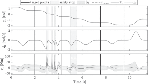
reports an example trajectory, in which position velocity and torque for the joint 1 of the manipulator are shown. In the plot on the bottom, the nominal torque of the robot is shown in black, together with the range of torques in dark grey, corresponding to whole set of values that can be obtained due to the uncertain parameters. As it can be seen from the figure, in some cases (as for instance, during a stop trajectory), the maximum torque could exceed the joint torque limits of the manipulator, if the proposed robust approach for the computation of the dynamics is not considered.
Figure 4. Example trajectory: position, velocity and torque for joint 1. Safety stops and uncertain torque bounds are represented as shaded areas, whereas vertical solid lines indicate target points.\.
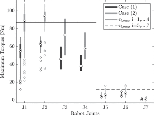
reports the box plot representation of the maximum available torques for Case (1) and (2) evaluated considering uncertain dynamics. In the box plots, the central point represents the median, the bottom and top of the box indicate the first and third quartiles, whereas the whiskers extend to the most extreme data points not considered outliers. As it can be seen from , the torques for Case (1), which correspond to robust stop trajectories optimized using an IA-RNEA approach, always respect the torque bounds. On the other hand, the maximum torques for Case (2) violates the joint torque limits in the 87% of the simulations. This verifies the robustness of the proposed approach and its applicability to the computation of the robot dynamics in case of parameter and payload uncertainties, making the suggested strategy a viable solution for manipulators with uncertain dynamics.
4.3. Influence of dynamics uncertainties on human-robot collaboration
To verify the influence of dynamics uncertainties on human-robot collaboration, simulations are run in which the dynamics of the robot is evaluated by means of the IA-RNEA approach, with the bounds of uncertain parameters as in Sect. 4.1. Furthermore, for each set of simulations the bound of the maximum payload is increased from to
with steps of
.
For comparison, not only the stop time of the robot and the radius of the safety zones are considered, but also quantitative metrics aimed to assess the performance of applications involving the collaboration or co-existence of robot and human operator (Hoffman Citation2019; Kokotinis et al. Citation2023). In particular, two fluency metrics for human-robot collaboration are taken into account: the total task time (T-TIME), and the number of robot stops (R-STOPS). The T-TIME equals the total time needed for the robot to reach all the prescribed five way points, considering safety stops and restarts into account. The R-STOPS metric indicates how many times the manipulator is stopped by the supervisory controller during the task in collaboration with the human. These two metrics directly account for the fluency in the collaborative operation and have a direct link to the productivity of the robotic application.
The results of the numerical simulations are reported in terms of box plots in , where the trend for the stop time, radii of the safety zones, total task time, and number of robot stops for different bounds of the maximum payload are shown. Furthermore, the mean values of these quantitative metrics and the percentage difference with respect to the nominal case are reported in for the considered bounds of the maximum payload. As it can be noticed, the stop time and, accordingly, the radii of the four safety zones enclosing the robot increase by increasing the maximum payload. Due to the progressive enlargement of the size of the robot dynamic safety zones with the payload, the fluency metrics of T-TIME and R-STOPS are also negatively affected. Indeed, as the maximum bound of the payload increases, the total time to complete the prescribed operation becomes higher, since the supervisory controller stops the robot more frequently due to potential collisions with the simulated human operator.
Figure 6. Numerical results: stop time (a), radii of the safety zones (b), total task time (c), and number of robot stops (d) for different bounds of the maximum payload.
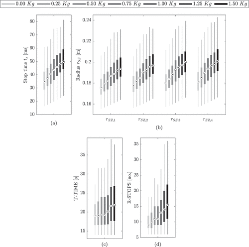
Table 1. Mean values of the quantitative metrics stop time, radii of the safety zones, total task time, and number of robot stops, as well as the percentage difference with respect to the nominal case () for different bounds of the maximum payload.
5. Conclusion
In this paper, an approach for computing online safety zones in a robust way, despite uncertain robot dynamics has been presented. The strategy implements the speed and separation monitoring paradigm, and considers human and robot enclosed in bounding volumes. The human-robot collaboration is monitored by a supervisory controller that guides the robot to stop along a path-consistent trajectory in case of collision danger between human and robot. The size of the robot safety zone is minimized online according to the stop time of the manipulator, and the uncertain robot dynamics is considered using interval arithmetic to ensure compliance with the joint torques limits even in case of imperfect knowledge of the dynamic model parameters.
The proposed approach has been verified with numerical simulations of a Franka Emika Panda robot with 7 DOFs. In the tests, the manipulator performs random trajectories, while a simulated human cyclically intrudes in the robot workspace, so as to induce safety stops of the robot. The results verified the effectiveness of the proposed approach, and evaluated the influence of dynamics variations on fluency metrics for human-robot collaboration.
As an extension of this work, the online computation of safety zones in a robust way can be further investigated by implementing the proposed approach on a physical robot in a real collaborative robotics application, e.g. for pick-and-place tasks of diverse objects in a workspace that is shared with a human collaborator. Further promising developments of the proposed strategy will also include the extension to mobile manipulators to evaluate the performance of the approach in terms of safety and fluency in more complex and challenging collaborative applications.
Disclosure statement
No potential conflict of interest was reported by the authors.
Correction Statement
This article was originally published with errors, which have now been corrected in the online version. Please see Correction http://dx.doi.org/10.1080/0951192X.2023.2262275
Additional information
Funding
References
- Althoff, M., and D. Grebenyuk. 2016. “Implementation of Interval Arithmetic in CORA 2016.” In Proc. of the 3rd International Workshop on Applied Verification for Continuous and Hybrid Systems, Vienna, Austria, 91–105.
- Byner, C., B. Matthias, and H. Ding. 2019. “Dynamic Speed and Separation Monitoring for Collaborative Robot Applications–Concepts and Performance.” Robotics and Computer-Integrated Manufacturing 58:239–252. https://doi.org/10.1016/j.rcim.2018.11.002.
- Choi, Y., D. Kim, S. Hwang, H. Kim, N. Kim, and C. Han. 2017. “Dual-Arm Robot Motion Planning for Collision Avoidance Using B-Spline Curve.” International Journal of Precision Engineering and Manufacturing 18 (6): 835–843. https://doi.org/10.1007/s12541-017-0099-z.
- Craig, J. J. 2006. Introduction to Robotics: Mechanics and Control. 3rd ed. Upper Saddle River, NJ, USA: Pearson.
- Ericson, C. 2004. Real-Time Collision Detection. Crc Press.
- Faroni, M., M. Beschi, A. Visioli, and N. Pedrocchi. 2021. “A Real-Time Trajectory Planning Method for Enhanced Path-Tracking Performance of Serial Manipulators.” Mechanism and Machine Theory 156:104152. https://doi.org/10.1016/j.mechmachtheory.2020.104152.
- Franka Emika. 2022. “Franka Description.” https://github.com/frankaemika/franka_ros/blob/develop/franka_description/robots/common/inertial.yaml.
- Gaz, C., M. Cognetti, A. Oliva, P. Robuffo Giordano, and A. De Luca. 2019. “Dynamic Identification of the Franka Emika Panda Robot with Retrieval of Feasible Parameters Using Penalty-Based Optimization.” IEEE Robotics and Automation Letters 4 (4): 4147–4154. https://doi.org/10.1109/LRA.2019.2931248.
- Giusti, A., S. B. Liu, and M. Althoff. 2021. “Interval-Arithmetic-Based Robust Control of Fully Actuated Mechanical Systems.” IEEE Transactions on Control Systems Technology 30 (4): 1525–1537. https://doi.org/10.1109/TCST.2021.3118488.
- Giusti, A., and C. Nainer. 2022. “Inverse Uncertain-Dynamics of Robot Manipulators Using Interval Arithmetic.” In Advances in Italian Mechanism Science - Proceedings of the Fourth International Conference of IFToMM ITALY, Naples, Italy, Springer.
- Grushko, S., A. Vysockỳ, D. Heczko, and Z. Bobovskỳ. 2021. “Intuitive Spatial Tactile Feedback for Better Awareness About Robot Trajectory During Human–Robot Collaboration.” Sensors 21 (17): 5748. https://doi.org/10.3390/s21175748.
- Gualtieri, L., E. Rauch, and R. Vidoni. 2022. “Development and Validation of Guidelines for Safety in Human-Robot Collaborative Assembly Systems.” Computers & Industrial Engineering 163:107801. https://doi.org/10.1016/j.cie.2021.107801.
- Hoffman, G. 2019. “Evaluating Fluency in Human–Robot Collaboration.” IEEE Transactions on Human-Machine Systems 49 (3): 209–218. https://doi.org/10.1109/THMS.2019.2904558.
- ISO. 2016. ISO/TC 299: ISO/TS 15066: 2016 Robots and Robotic Devices–Collaborative Robots. Geneva: International Organization for Standardization.
- Kaltsoukalas, K., S. Makris, and G. Chryssolouris. 2015. “On Generating the Motion of Industrial Robot Manipulators.” Robotics and Computer-Integrated Manufacturing 32:65–71. https://doi.org/10.1016/j.rcim.2014.10.002.
- Kim, E., Y. Yamada, S. Okamoto, M. Sennin, and H. Kito. 2021. “Considerations of Potential Runaway Motion and Physical Interaction for Speed and Separation Monitoring.” Robotics and Computer-Integrated Manufacturing 67:102034. https://doi.org/10.1016/j.rcim.2020.102034.
- Kokotinis, G., G. Michalos, Z. Arkouli, and S. Makris. 2023. “On the Quantification of Human-Robot Collaboration Quality.” International Journal of Computer Integrated Manufacturing 1–18. https://doi.org/10.1080/0951192X.2023.2189304.
- Kot, T., R. Wierbica, P. Oščádal, T. Spurnỳ, and Z. Bobovskỳ. 2022. “Using Elastic Bands for Collision Avoidance in Collaborative Robotics.” Institute of Electrical and Electronics Engineers Access 10:106972–106987. https://doi.org/10.1109/ACCESS.2022.3212407.
- Lagomarsino, M., M. Lorenzini, E. De Momi, and A. Ajoudani. 2022. “Robot Trajectory Adaptation to Optimise the Trade-Off Between Human Cognitive Ergonomics and Workplace Productivity in Collaborative Tasks.” In 2022 IEEE/RSJ International Conference on Intelligent Robots and Systems (IROS), Kyoto, Japan, 663–669. IEEE.
- Lange, F., and A. Albu-Schäffer. 2015. “Path-Accurate Online Trajectory Generation for Jerk-Limited Industrial Robots.” IEEE Robotics and Automation Letters 1 (1): 82–89. https://doi.org/10.1109/LRA.2015.2506899.
- Lin, Y., and S. Saripalli. 2017. “Sampling-Based Path Planning for UAV Collision Avoidance.” IEEE Transactions on Intelligent Transportation Systems 18 (11): 3179–3192. https://doi.org/10.1109/TITS.2017.2673778.
- Merckaert, K., B. Convens, W. Chi-Ju, A. Roncone, M. M. Nicotra, and B. Vanderborght. 2022. “Real-Time Motion Control of Robotic Manipulators for Safe Human–Robot Coexistence.” Robotics and Computer-Integrated Manufacturing 73:102223. https://doi.org/10.1016/j.rcim.2021.102223.
- Moore, R. E., R. Baker Kearfott, and M. J. Cloud. 2009. Introduction to Interval Analysis. Philadelphia: Society for Industrial and Applied Mathematics.
- Palleschi, A., M. Hamad, S. Abdolshah, M. Garabini, S. Haddadin, and L. Pallottino. 2021. “Fast and Safe Trajectory Planning: Solving the Cobot Performance/Safety Trade-Off in Human-Robot Shared Environments.” IEEE Robotics and Automation Letters 6 (3): 5445–5452. https://doi.org/10.1109/LRA.2021.3076968.
- Pereira, A., and M. Althoff. 2017. “Overapproximative Human Arm Occupancy Prediction for Collision Avoidance.” IEEE Transactions on Automation Science and Engineering 15 (2): 818–831. https://doi.org/10.1109/TASE.2017.2707129.
- Roehm, H., J. Oehlerking, M. Woehrle, and M. Althoff. 2019. “Model Conformance for Cyber-Physical Systems: A Survey.” ACM Transactions on Cyber-Physical Systems 3 (3): 1–26. https://doi.org/10.1145/3306157.
- Rojas, R. A., A. Giusti, and R. Vidoni. 2022. “Online Computation of Time-Optimization-Based, Smooth and Path-Consistent Stop Trajectories for Robots.” Robotics 11 (4): 70. https://doi.org/10.3390/robotics11040070.
- Safeea, M., P. Neto, and R. Bearee. 2019. “On-Line Collision Avoidance for Collaborative Robot Manipulators by Adjusting Off-Line Generated Paths: An Industrial Use Case.” Robotics and Autonomous Systems 119:278–288. https://doi.org/10.1016/j.robot.2019.07.013.
- Scalera, L., A. Giusti, R. Vidoni, and A. Gasparetto. 2022a. “Enhancing Fluency and Productivity in Human-Robot Collaboration Through Online Scaling of Dynamic Safety Zones.” International Journal of Advanced Manufacturing Technology 121 (9): 6783–6798. https://doi.org/10.1007/s00170-022-09781-1.
- Scalera, L., A. Giusti, R. Vidoni, and A. Gasparetto. 2022b. “Online Planning of Path-Consistent Stop Trajectories for Collaborative Robotics.” In Advances in Italian Mechanism Science - Proceedings of the Fourth International Conference of IFToMM ITALY, Naples, Italy, Springer.
- Scalera, L., R. Vidoni, and A. Giusti. 2021. “Optimal Scaling of Dynamic Safety Zones for Collaborative Robotics.” In 2021 IEEE Int. Conf. on Rob. and Autom. (ICRA), Xi’an, China, 3822–3828. IEEE.
- Secil, S., and M. Ozkan. 2022. “Minimum Distance Calculation Using Skeletal Tracking for Safe Human-Robot Interaction.” Robotics and Computer-Integrated Manufacturing 73:102253. https://doi.org/10.1016/j.rcim.2021.102253.
- Seriani, S., P. Gallina, L. Scalera, and V. Lughi. 2018. “Development of N-Dof Preloaded Structures for Impact Mitigation in Cobots.” Journal of Mechanisms and Robotics 10 (5): 051009. https://doi.org/10.1115/1.4040632.
- Siciliano, B., L. Sciavicco, L. Villani, and G. Oriolo. 2010. Robotics: Modelling, Planning and Control. Springer Science & Business Media. https://doi.org/10.1007/978-1-84628-642-1.
- Trigatti, G., P. Boscariol, L. Scalera, D. Pillan, and A. Gasparetto. 2018. “A Look-Ahead Trajectory Planning Algorithm for Spray Painting Robots with Non-Spherical Wrists.” In IFToMm Symposium on Mechanism Design for Robotics, 235–242. Springer. https://doi.org/10.1007/978-3-030-00365-4_28.
- Vicentini, F. 2021. “Collaborative Robotics: A Survey.” Journal of Mechanical Design 143 (4). https://doi.org/10.1115/1.4046238.
- Zanchettin, A. M., P. Rocco, S. Chiappa, and R. Rossi. 2019. “Towards an Optimal Avoidance Strategy for Collaborative Robots.” Robotics and Computer-Integrated Manufacturing 59:47–55. https://doi.org/10.1016/j.rcim.2019.01.015.
Appendix A.
Nominal kinematics and dynamics parameters of the Franka Emika robot
Table A1. Nominal parameters of the Franka Emika robot used in the numerical simulations from (Franka Emika Citation2022). ,
,
and
are the parameters of the modified Denavit – Hartenberg convention (Craig Citation2006);
represents the mass;
,
,
are the center of mass coordinates;
,
,
,
,
,
are the inertia tensor elements;
,
are the viscous and coulomb friction model coefficients (obtained by fitting the parameters of the friction model found in (Gaz et al. Citation2019.)).

