
 ?Mathematical formulae have been encoded as MathML and are displayed in this HTML version using MathJax in order to improve their display. Uncheck the box to turn MathJax off. This feature requires Javascript. Click on a formula to zoom.
ABSTRACT
This paper introduces the human-robot and multi-robot programming and simulation capabilities of a web-based, open-source robot programming and simulation tool called Assembly. The tool supports scenarios with up to three robots and provides support for simulating human arms working closely with a robot. To facilitate the simulation of scenarios involving human-robot and robot-robot collaboration, the paper proposes an improved version of the neural network-based Adaptive Simplex Motion Planner, which is capable of performing motion planning at a rate of over 3500 Hz. The improved toolpath planner uses an obstacle avoidance approach that leverages ray casting and shadow volume teachniques. The new planner is evaluated on the basis of two human-robot and multi-robot simulation scenarios and the results are compared to those of the original algorithm.
1. Introduction
Human-robot collaboration (HRC) is based on physical and cognitive interactions between humans and collaborative robots (cobots). Cognitive engagement enables users to create, operate, and program cobots using little or no programming knowledge. By contrast, physical interaction alone requires laborious risk assessments and safe workspace designs. Physical interaction usually concerns factory employees, who are often regarded as ‘irresponsible’ cobot users, for whom experts need to implement safety barriers (Ionescu and Schlund Citation2019, Citation2021). However, especially in non-industrial contexts, HRC builds on cognitive rather than physical interactions (Ionescu Citation2020). This suggests that the adoption of cobots beyond industrial contexts is a function of the accessibility of programming tools with respect to lay users and self-taught experts.
Before and during the COVID-19 crisis, a trend towards moving cobot user interfaces from proprietary user interfaces to web-based environments could be observed. Due to access restrictions to labs and factories, training activities have moved online during the pandemic. At the same time, there is an increasing interest by companies from the manufacturing domain in web-based, end-user robot programming environments that work with a wide range of robots (Huang et al. Citation2018; Ionescu Citation2021b). These tools not only help to avoid vendor lock-in but also to retrofit older robots with new software. Unfortunately, most existing web-based robot programming tools are still proprietary. For example, the app-oriented Franka Emika Desk environment (Franka Emika Citation2021) is only available for Franka Emika cobots; and the robot-independent Drag & Bot tool (drag and bot GmbH Citation2020) is only available for licensed users. Two additional drawbacks of existing web-based robot programming tools are that (1) they do not provide multi-robot programming and simulation capabilities (i.e. programming and visualizing multiple robots as part of a unified simulation), and (2) they do not provide means for experimenting with machine learning-based motion planning algorithms.
This paper introduces key features of a web-based multi-robot programming and simulation tool, called Assembly (), which provides a playground for experimenting with machine learning-based motion planning algorithms by integrating a lightweight machine learning (ML) framework called Brain.js. The tool is designed for people without programming experience. Existing end-user programming tools usually provide compelling robot rendering capabilities (e.g. based on comprehensive CAD models). By contrast, Assembly takes a radically different approach based on looking at cobots as ‘computers that move’ rather than programmable machines. This minimalist approach has the advantage that the focus is put on the programming task rather than on fancy visualizations. A further advantage is that new features can be implemented with relatively easy programming efforts.
Figure 1. The assembly tool is available at https://github.com/CoMeMak/assembly.
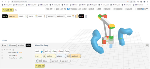
Assembly builds on the inherent features of common web browsers. For example, multiple robots can be instantiated in different browser windows or tabs. A multi-robot simulation is enabled by designating one of the robot windows as being the host environment. Robot programs can be saved as bookmarks in the browser’s bookmarks bar. A web-native 3D animation framework (Three.js) is used to visualize and animate robots, human models, and objects in a ‘frugal’ way. The so-called Web Speech API is used for voice-based robot programming and the tool also provides a neural network-based toolpath planning algorithm that supports dynamic obstacle avoidance. This motion planner can be instrumental in testing human-robot and multi-robot collaboration applications for productive, educational, and leisure purposes. All these features arguably make for an unconventional, progressist robot tool, which invites people to experiment and improve it.
The main scientific contribution of this paper is an improved collision-free, dynamic toolpath planning approach called Corrected Adaptive Simplex Motion Planner (CASMP). To support this contribution, the paper also introduces a novel multi-robot programming and simulation features of Assembly and simplified yet versatile and efficient rendering technique for robots based on the Catmull-Rom spline curve and so-called tube geometries.
2. Related work
2.1. End-user robot programming
Simplified and multimodal programming models allow users to configure robot skills and behaviors as well as to teach toolpaths directly on the shop floor. They use graphical elements and various logical structures to make programming more intuitive and accessible for non-experts (Bravo, González, and González Citation2017; Ionescu Citation2021b; Steinmetz, Wollschläger, and Weitschat Citation2018a; Weintrop et al. Citation2018).
Desk is the human-robot interface of the Franka Emika Panda Cobot (Franka Emika Citation2021). Desk implements a workflow-based, skill-oriented programming model, which resembles smart phone and tablet user interfaces in terms of concepts, look and feel. The human-robot interaction (HRI) device connects to the robot via a wired or wireless Ethernet connection. Desk is an online robot programming tool. Depending on the HRI device used, the programming can be performed using the touch screen or the mouse and keyboard. Desk leverages a library of so-called apps, which implement robot skills and behaviors. To program the robot, the user instantiates apps by dragging and dropping them from the app library to the workflow area in a sequence. Each app is configured individually using a configuration wizard. The resulting workflows are called tasks. Desk supports bimodal programming using mouse, keyboard, and touchscreen inputs on the HRI device and haptic inputs mounted directly onto the robot.
Drag&Bot is a web-based simplified generic robot programming tool that runs in a web browser (drag and bot GmbH Citation2020). Drag&Bot supports about a dozen collaborative and non-collaborative robots from different vendors. The tool supports both programming and simulating these robots. The source code of the tool is proprietary and the license costs are high.
RAZER (Steinmetz et al. Citation2018a) is another web-based tool for programming by demonstration. It is skill-oriented, like Drag & Bot, and programming is performed by configuring off-the-shelf skills in a similar manner as in Franka Emika Desk. An expert mode for creating new skills is also available. There is no public version of RAZER available.
A later version of RAZER (Steinmetz et al. Citation2019) improves the programming experience using a semantic model for automated configuration of skills. This is achieved by observing the interactions that a human performs when programming a robot by demonstration and matching different actions to robot skills supported by the tool.
Halt et al. (Citation2018) propose a robot programming model based on the standardized automated handling functions described in the VDI norm 2860. The system matches sequences of program actions to standard handling functions using constraint-based reasoning. The result is a generated robot program containing sequences of handling functions described in VDI 2860, which can be modified by the user.
Schäfer et al. (Citation2021) developed a semantic, skill-oriented robot programming tool for end users called Human Factory Interface (HFI). The tool uses SPARQL to query a knowledge graph to program, reconfigure, schedule, and plan production processes involving robots. The representations are conformant with to the IEEE 1872 standard. HFI provides a web-based interface for programming robot tasks declaratively. These tasks are then assigned to a specific robotic assembly cell. A similar approach is also presented in (Wildgrube et al. Citation2019).
The recently standardized Web Speech API (WSAPI) provides speech recognition capabilities directly in web browsers. The WSAPI has been used to extend Franka Emika Desk by speech-based programming capabilities (Ionescu and Schlund Citation2021b). The speech API can be used from JavaScript. With only a few lines of code, robot programming instructions can be associated to speech commands. Using this browser extension, the user can instantiate and configure the robot skills that are available in the Franka Emika Desk UI by issuing voice commands while manually teaching robot positions. The approach reduces the time for programming by demonstration in half. This approach is applicable to all web-based robot programming UIs. A plugin-based approach to extend ABB RobotStudio by voice-based commands to control robots is also presented in Pires and Azar (Citation2018).pi tpb 3pt
2.2. Collision-free motion planning
Approaches based on neural networks and other machine learning technologies have been used to implement collision-avoidance mobile robot navigation. For indoor obstacle avoidance, convolutional neural networks (CNN) (Tai et al. Citation2016) and reinforcement learning (Tai et al. Citation2017) have been successfully applied. While deep reinforcement learning does not require manually constructed features or earlier demonstrations to train the model, CNNs use raw images as input and output control commands. Zhu et al. (Citation2017) introduce an approach based on deep reinforcement learning applied to the navigation of mobile robots, which leverages training data produced by means of a simulation tool in consideration of potential physical interactions of the robots with their environment. Wang et al. (Citation2018) and Cimurs et al. (Citation2020) also discuss the use of reinforcement learning for navigation in complicated dynamic situations.
The current techniques for obstacle avoidance for robot arms (serial manipulators) use a variety of strategies for combinatorial search to identify feasible, collision-avoiding robot poses along a route. The search strategies include evolutionary algorithms (Larsen and Kim Citation2021; Larsen et al. Citation2018) and various versions of the Rapidly Exploring Random Tree method (Ge, Sun, and Liu Citation2017; Lavalle and Kuffner Citation2000; LaValle and Kuffner Citation2001; Wei and Ren Citation2018). These planners take into consideration the possibility of all the robot’s joints colliding with the obstacle(s), thus making them complete planners. This leads to high computation times, which makes the application of these algorithms difficult in productive environments.
Jia et al. (Citation2020) propose a reinforcement learning-based approach to manipulate objects by a six degrees of freedom robot. Various methods for printing on arbitrarily shaped 3D surfaces using a 6-DOF manipulator are introduced in (Ji, Zhang, and Wang Citation2019; Thomsen et al. Citation2020).
Ji et al. (Citation2019) propose a Q-learning-based approach for path planning while taking joint motions into account. The method builds on considering approximate regions rather than precise measurements. For solving the collision-free motion planning problem for the case of generic manipulators having up to 80 joints, Otte et al. (Citation2018) propose a method based on regenerative recurrent neural networks. Reinforcement learning is used in the SAC-HER method (Prianto et al. Citation2020) to plan trajectories of a two-arms robot, with both arms having 3 degrees of freedom. Both arms are considered in the planning as if they were a single entity, which is equivalent to planning for a 6-DOF robot. A similar Soft Actor-Critic (SAC)-based method (Wong et al. Citation2021) extends the SAC–HER approach for a dual 7-DOF arm robot. This planner, however, does not guarantee the success of the planning task considering the high number of degrees of freedom.
Alternative approaches to heuristic path planning techniques include analytical, curve-based path planning approaches (M. W. Otte Citation2015). Instead of planning motions in the configuration space of the robot, the planning is carried out in the task space by optimizing parametric curves, such as the Bézier or the Lamé curve. For example, support vector machines (SVM) have been used by Miura (Citation2006) to create a smooth path between two points in a way that avoids collisions with obstacles in 2D and 3D space. The points of the obstacles are divided into two clusters using the SVM. The outcomes are then utilized to create a smooth curve that fits the points from different clusters of points. Other methods produce collision-free motion trajectories for moving robots and vehicles using parametric curves like Bézier (Elhoseny, Tharwat, and Hassanien Citation2018; Han et al. Citation2010) or Clothoid (Shimizu, Kobayashi, and Watanabe Citation2006) curves. These parametric curves can be utilized to create collision-free routes in intricate situations because they are adaptable. The Lamé curve, which has a more straightforward formulation is used in the dynamic toolpath planning approach in (Ionescu, Citation2021a), which is called Adaptive Simplex Motion Planner (ASMP). This curve will also be used in the improved version of the ASMP introduced in this paper. The Lamé curve is defined by three parameters that can be adjusted according to the geometry of the obstacle. This formulation makes it easier to build a machine learning model that can estimate these three parameters. The Lamé curve has been utilized in robotics to plan smooth trajectories for parallel (Zhang and Ming Citation2019) and Delta (Chen et al. Citation2017; Xie, Shang, and Ren Citation2015; Xie, Wu, and Ren Citation2016) robots.
2.2.1. Human-robot collision-free motion planning
With the increasing adoption of collaborative robots, the problem of planning collision-free robot motions in close proximity of humans has become central in manufacturing (Tsarouchi, Makris, and Chryssolouris Citation2016). Approaches in this sense tend to be either human-centered or robot-centered. As an example of the formed, De Schepper et al. (Citation2023) propose an approach that fuses force-torque data and skeleton tracking to control a mobile manipulator intuitively. To this end, the intelligence of the operator is leveraged as much as possible, thereby rendering path planning and object modelling non-essential for the task. Other approaches build on augmented reality to render visible the motion plans of mobile manipulators, thus allowing humans to adapt to the robot´s movements (Aivaliotis et al. Citation2023). Krämer et al. (Citation2020) propose a model-predictive control-based approach that monitors the distance between the end effector and one or several moving obstacles for planning a motion trajectory for a 6-DOF robot. Although this method does not specifically target human-robot collaboration, it is well suited for it thanks to the high performance of the planner for dynamic obstacles and, intuitively, comes closed to the CASMP planner.
2.2.2. Multi-robot collision-free motion planning
The problem of planning collision free motions of multiple robots sharing a workspace, notably redundant and mobile manipulators, is still challenging. Older approaches, such as (Seo, Ko, and Simmons Citation2009), focus on mobile manipulators that need to avoid each other in a shared workspace by means of a collision-free motion coordination method for multiple robots based on an enhanced elastic force approach for collision avoidance and employs prioritization-and-avoidance, where robots with lower priority avoid those with higher priority.
Recently, Bakker et al. (Citation2023) by an approach called Rollout Fabrics (RF). Fabrics are structures or frameworks that aid in modeling, simulating, and planning the motion of robots in their environment. RF is an online local motion planning algorithm that allows the simultaneous operation of multiple high DOF manipulators within a shared workspace. Local motion planning is an approach where a global motion plan between a source and a target point may be computed using another planner beforehand, whereby at each step a local motion planner performs dynamic replanning between two established waypoints or intermediate joint configurations to avoid (dynamic) obstacles. This has the advantage that slow, global motion planners can be adapted for dynamic obstacle avoidance. RF is a decoupled approach in the sense that the motion of different robots is planned independently. While this approach has the advantage of being less complex than coupled approaches in which the motion is planned jointly for several manipulators, thus increasing the DOF for which planning must be performed, it has the disadvantage of potential deadlocks. A deadlock emerges when two robots move toward each other while considering other robots as being dynamic obstacles. However, since all robots compete for the same shared space, they are very likely to enter into a collision state. RF uses a heuristic approach to address deadlocks that builds on adapting the goal-reaching parameters of the fabric formulation. RF extends the dynamic optimization fabrics (OF) method for motion generation (Spahn, Wisse, and Alonso-Mora Citation2023), which is an approach to real-time local motion generation in which motions are modelled using several differential equations that exhibit a desired motion behavior. The OF method, however, is not designed to account for multiple robots and therefore does not deal with deadlock situations. One example of a coupled multi-robot motion planner is dRRT* (Shome et al. Citation2020), which builds on the classic Rapidly Exploring Random Trees (RRT) planner. dRRT* plans motions for multiple robots by building roadmaps for each of them and searching the composite configuration space of the robots.
The CASMP motion planner described in this paper uses a strategy that is similar to that of the RF planner: It starts from a global motion plan (e.g. a direct trajectory between a source and a target pose) and then adapts the plan depending on the obstacles encountered.
3. Programming multiple robots with Assembly
Assembly uses the ‘blackboard’ pattern for data flow (). The Blackboard design pattern enables several knowledge sources (i.e. agents or actors) to share data within the same memory region or variable space. Assembly uses this concept to facilitate the creation and instantiation of actors by dragging and dropping them to a workflow pane in the user interface of the tool. The blackboard in Assembly consists of four so-called context objects, called Robot, Params, Vars, and Task. Parameters and variables are stored in these context objects.
Figure 2. High-level architecture of Assembly.
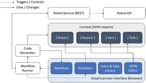
The implementation follows the ‘convention over configuration’ principle, which does not require strong interfaces between actors and the execution engine of Assembly. For users, there are several advantages to this approach as well. First, they can sketch a robot program without specifying any parameter or variable value. These only need to be specified later. And second, novice users are encouraged early on to learn how to create and assign variable and parameter values using a text-based editor, which is an important step in learning how to program robots. And third, users can also use JavaScript expressions provided as variables that are evaluated at runtime.
Assembly builds on an open-source 6-DOF simulator for generic robots (Beck Citation2021) written in JavaScript that uses Three.js as the animation framework. The simulator is capable of rendering and computing the inverse kinematics of generic 6-DOF robots. On top of that basic simulator, the Assembly simulator supports multiple robot models as well as multi-robot and human-robot simulation. Currently, the user can choose from Universal Robots 3, 5, 10, and 16. This allows exploring scenarios where robots of different dimensions are working close together.
3.1. Robot-to-robot communication
The communication between the robots implements the publish-subscribe architectural style (). From a technical point of view, the communication occurs between different browser processes (i.e. windows or tabs). From the logical point of view, robot programs can send messages to communicate their state to other active sessions using named signals. Assembly provides two designated actors to enable inter-session communication. The Send Signal actor broadcasts a predefined (i.e. named) signal to all other active sessions, which listen for signals. The Await Signal actor listens for a specified signal (e.g. signal 1, 2, 3, etc.). Using this simple communication mechanism, coordination between multiple robots can be achieved. Although this approach may seem rudimentary, it is based on the philosophy of robot simulation implemented by Assembly, namely that robots are computers that move. Within this model, the communication does not occur between specific robots and sessions but according to the blackboard pattern. By broadcasting a specific signal, the program writes that signal to the blackboard, and by awaiting a specific signal, the program reads from the blackboard. As long as the blackboard is kept clean and simple, there is no need for a more complex kind of communication between robots. Assembly programmers can think of the robots as dancers and of programs as a choreography based on signals.
Figure 3. Communication architecture.
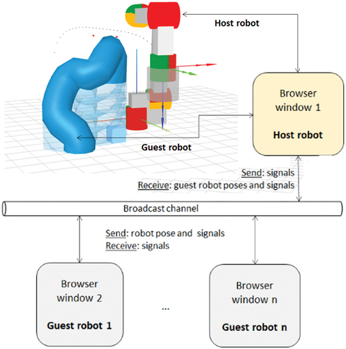
In addition to signals, the robots also broadcast their poses periodically (e.g., every 100 ms). This enables the rendering of guest robots within a host robot session.
3.2. Robot rendering
The host robot is rendered using solid geometries, like boxes and cylinders. This rendering is based on the original Glumb simulator. Guest robots and human arms are rendered in a simplified yet compelling way using a minimalistic technique, called ‘frugal’ rendering. This minimalistic representation provides essential information about the guest robots, including their dynamically changing pose in the workspace of the host robot. Frugal rendering is goal-oriented rather than aesthetics-oriented. When working with multiple robots in Assembly, one of the primary goals is to simulate collision-free, dynamic robot motion planning rather than to design complex workstations. Currently, one host and two guest robots can be represented in the same scene, whereby the host robot uses dynamic motion planning to avoid colliding with the other robots.
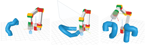
The rendering of the guest robots is implemented using the so-called tube geometry of Three.js. This geometry is instantiated using a spline curve that defines the joint positions of the robot or the human arms. In Assembly, the Three.js implementation of the Catmull-Rom spline curve is used (Catmull and Rom Citation1974). Along such a curve, a 3D flexible tube is generated. The diameter of the tube can be adapted to the guest robot (i.e. robot model, number of joints, and scale). This enables minimalistic, efficient, and suggestive guest robot rendering, which differs from many mainstream robot simulation tools, which provide more realistic robot models. By contrast, in Assembly, the goal of the rendering style is to stimulate the users’ focus on the abstracted and generic nature of the programming task, which is completely independent of the robot’s model and aesthetics. Using the tube geometry, it is possible to render one or several robots as well as a pair of human arms, as depicted in . In the ‘one host, one guest’ configuration (, left), the guest robot is rendered starting from the six joint positions that define its pose. In the human-robot configuration (, middle), the human arms are rendered using eight points: the position of the shoulder, elbow, and ankle joints; and the approximate position of the fingertips. In the ‘one host and two guest robots’ configuration (, right), the guest robots are rendered as distinct tubes. Any number of guest robots can be represented this way.
Figure 4. Rendering capabilities in Assembly: one host and one guest robot (left); one host robot with human arms and protection window (middle); one host and two guest robots (right).
Minimalist designs are known to foster learning and creative authoring in the field of human-centric computing (Seals et al. Citation2002). The minimalistic rendering of robots allows the programmers to focus on programming rather than on the aesthetic aspects of the simulation, which is useful in educational contexts. In the field of game development, minimalistic rendering is also used for reasons of cost effectiveness, performance, and complexity management.
3.3. Dynamic obstacle detection
Detecting moving obstacles is a prerequisite for collision-free dynamic motion planning. In the Assembly simulator, obstacle detection is performed using a ray casting technique that is optimized for (simulated) human and robot arms. Ray-casting is a technique for detecting objects by tracking the intersection points of rays that are cast through a scene. The technique provides information about the objects being hit, notably object IDs and intersection positions. A prerequisite for using ray casting for obstacle detection is to also account for the free space below any of the obstacles. Common solutions to this problem are bounding boxes or spheres computed around the obstacles. However, bounding structures are spatially inefficient because they cover a much larger space than needed, thus unnecessarily reducing the working space of the robot. For these reasons, in Assembly, the so-called shadow volume (McCool Citation2000) of each volume is generated by considering a directional light source placed above each respective obstacle. Such a light source produces an orthographic projection on the obstacle’s silhouette on the ground. Shadow volume-based techniques are well-known in the context of robot path planning (Hornung, Neubauer, and Müller Citation2022). In Assembly, the shadow volume is used to extend the volume of the obstacle downward (or, generally speaking, in the opposite direction of the light source), thus filling the entire free space below each of its points. Extending each obstacle by its downward shadow volume then allows the use of a simple ray-casting technique to detect and account for several obstacles along a direct motion path. Even if the ray passes beneath some part of an obstacle along the TCP trajectory, it will always intersect its shadow volume.
Because Three.JS does not provide support for generating the shadow volume of arbitrary geometries, to approximate the shadow volume of each obstacle, the tube geometry of the guest robot is replicated downwards with a negative offset on the Z-axis with respect to the previous (virtual) tube geometry equal to the diameter of the tube geometry, as shown in . The result is an approximation of the shadow volume of the obstacle when considering a diffuse light source placed above it. To find the collision points with respect to the closest obstacle, two rays are cast; one originating in the robot’s TCP initial position and directed toward the final position (i.e. target) of the move, and another one originating in the motion target (with respect to the TCP). As the robot’s TCP advances toward the target, the ray casts are updated continuously such that the source of the first ray cast has its x and y-coordinates in the origin of the motion (with respect to the TCP), and its z-coordinate coincides with the current z-coordinate of the TCP. The second ray cast, with its origin in the motion target point (with respect to the TCP), is directed such that it passes through the dynamically recomputed origin of the first ray.
Figure 5. Replicated virtual tubes (RVT) technique with height-adjusted intersection points.
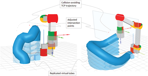
The collision points detected with the help of the two rays are translated vertically as necessary, depending on which of the replicated tube geometries are being intersected by the rays. These collision points form the basis of the TCP path planning algorithm described in the next section. The adjusted (i.e. translated) collision points are referred to as intersection points. An example is shown in . The intersection points account for the actual geometry of the human or robot arm and the offset of the virtual tube that is being intersected. It is assumed that the motion planner will avoid the obstacle in a cross-plane formed by the origin and target of the motion, and the adjusted intersection points.
3.3.1. Collision-free toolpath planning
The toolpath planning approach implemented in the latest version of Assembly builds on the toolpath planning approach introduced in (Ionescu Citation2021a), called Adaptive Simplex Architecture (ASA). This approach is based on predicting in real time, using a neural network, the three parameters of a Lamé curve equation that successfully avoids a moving obstacle at any time. Although the Lamé curve equation is used, which corresponds to a so-called super-ellipse, the resulting toolpath is not always elliptical since the replanning is continuous. In fact, the resulting trajectory is smooth and can take arbitrary shaped, as shown in , depending on the obstacle’s dynamics. The planning is performed by switching to different ‘orbits’ depending on the current position of the obstacle. These orbits are defined by different parameterizations of the Lamé curve, which can itself take various shapes, as shown in . This paper discusses an improved version of the ASA (Ionescu Citation2021a; Ionescu and Fröhlich, Citation2022), which increases the reliability of the neural network model from approximately 95% to 100% in the tested scenarios. This section starts by introducing the original planning algorithm before describing the improvements brought to the ASA model.
Figure 6. Dynamic toolpath planning using a neural network model for predicting the lamé curve parameters.
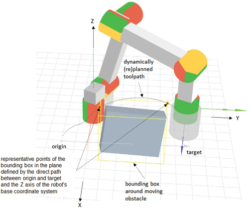
Figure 7. A.) different possible shapes of the lamé curve equation; b.) formulation of the optimization problem in terms of the lamé curve equation; c.) projection of the obstacle onto a 2D-plane aligned with the direct path from origin to target on the X’ axis and with the Z axis of the robot’s coordinate system on the Y’ axis.
We consider a dynamic path planning problem for a 6-DOF manipulator. The path planner recomputes the parameters of a curve-based trajectory of the end effector of an industrial robot arm in each control cycle so that the toolpath avoids any collisions while attempting to minimize the total toolpath length.
illustrates the basic idea of the planner. The moving obstacle can be composed of multiple objects of any shape and size. The moving obstacle may be a human, a human body part, or another robot or part of the robot. The example in assumes that a bounding box around the obstacle is being computed. As discussed in the previous section, however, with the improvements brought to the path planning algorithm proposed in this paper, a bounding box is no longer needed if another model of the one or more obstacles is provided as part of the simulation. This model should also support the ray casting techniques. If the obstacle is composed of one or more robots, a ‘frugal’ robot model can be generated from the joint positions. If the obstacle is composed of human arms, a camera such as Microsoft Kinect can be used to first detect the positions of the joints of the human arms (wrist, elbow, shoulder, etc.). In this paper, other kinds of objects are not being considered.
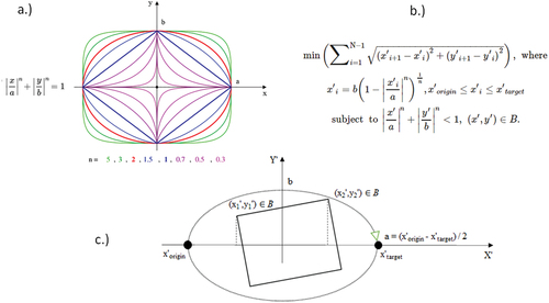
The toolpath is computed in the robot’s global coordinate system, and in relation to the robot’s tool center point (TCP). In , the problem is to find a smooth toolpath between the origin and target that (1) minimizes length and (2) avoids a moving object at all times. One approach to solving this problem is to use different parameterizations of the Lamé curve equation, as shown in . This approach facilitates a simple path planning problem formulation as an optimization problem, which can be solved using machine learning.
The Lamé curves takes a variety of shapes depending on the a (semi-major axis), b (semi-minor axis), and n (shape) parameters, as shown in . This enables the flexible generation of toolpaths that avoid collisions with at least one obstacle, which is characterized by two representative points, p1 = (x1’, y1’) and p2 = (x2’, y2’), in a plane defined by the direct path between origin and target, and the Z axis in the robot’s base coordinate system. In , N denotes the discrete segment number of an elliptical path between origin and target, and B denotes the representative points of the bounding box B = {p1, p2}, where p1 = (x1’, y1’) and p2 = (x2’, y2’) in .
The Lamé curve parameters a, b and n are being recomputed in real time as the obstacle is moving in a way that minimizes the path while avoiding the obstacle. The parameter a can be set to half the length of the direct path between x’origin and x’target. To determine the other two parameters, a combinatorial optimization algorithm can be used. Such an algorithm is presented in (Ionescu Citation2021a).
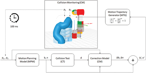
3.4. Motion planning strategy and architecture
shows the motion planning strategy and architecture used in Assembly. This approach builds on (Ionescu Citation2021a) in that it uses a neural network model as motion planner and the Lamé curve equation to generate the motion trajectory. This model (henceforth referred to as motion planning model – MPM) is trained using data produced by a hand-coded algorithm for finding the optimal parameters b and n, as described in (Ionescu Citation2021a). Given the coordinates of two characteristic points p1 and p2 (which are determined using the ray casting approach described in section 3.3.) as input, the MPM model estimates the parameters b and n of a Lamé-curved trajectory of the toolpath that avoids collisions with the obstacle characterized by p1 and p2. The characteristic points are updated every 100 ms, which means that the entire cycle from is executed once every 100 ms (i.e. 10 Hz). For a browser-based simulation, 10 Hz represents a reasonable value for ensuring a compelling animation. In a real robot, this cycle can be faster (e.g. up to 200 Hz) depending on the capabilities of the controller.
Figure 8. Motion planning strategy and architecture used in Assembly.
3.4.1. Motion planning model
Artificial neural networks (ANN) are universal function approximators, which allows them to accurately approximate polynomial objective functions (Villarrubia et al. Citation2018). This enables the training of an ANN model designed to learn and approximate solutions to various optimization problems from data that is generated using human-engineered solutions to those problems. To solve the toolpath planning problem, a feedforward ANN was trained with I = (x′origin, x′target, x′1, y′1, x′2, y′2) as the input and the Lamé curve parameters, b and n, as the output. This network is able to predict accurate solutions to the equation from . The human-engineered algorithm described in (Ionescu Citation2021a) can be used to generate training data for the neural network.
The architecture of the ANN used for toolpath planning is simple: 4 inputs and 2 outputs consisting of ‘min – max’ normalized numbers; 4 hidden layers having 32, 32, 32, and 16 neurons, respectively; and the sigmoid activation function. The sigmoid function outputs a floating-point number between 0 and 1 and was chosen because the b and n parameters of the Lamé curve are strictly positive numbers. A baseline MPM was first trained based on 10,000 input cases that were uniformly distributed over the problem space.
3.4.2. Collision test
To assert that the Lamé-curved toolpath trajectory generated using the b and n parameters predicted by the MPM avoids a collision with the obstacle, a collision test (CT) is used, as shown in . This collision test does not check whether other parts of the robot are on a trajectory of collision with the obstacle and is performed independently during the motion.
The purpose of the collision test (CT) is to decide whether the pair of characteristic points p1 = (x′1, y′1) and p2 = (x′2, y′2) lie inside the Lamé curve defined by (b, n), as computed by the MPM. The following inequality from provides a condition that enables the implementation of an acceptance test:
The input to the CT is represented by the coordinates of the representative points, p1 = (x′1, y′1) and p2 = (x′2, y′2), and the parameters (b, n) of the Lamé curve being tested. The output of the test is a so-called deviation from the optimal trajectory, d, which reflects the maximum distance between the representative points, p1 and p2, of the obstacle and the Lamé curve, with:
If the deviation parameter d > 1, an adjustment of the b and n parameters is necessary to avoid collision. If d ≤ 0, a collision is avoided, and no adjustment of the parameters b and n is necessary.
3.4.3. Correction model
For the cases in which d > 0, an adjustment of the parameters b and n is computed by the so-called correction model (CM), which takes as input the b and n, as predicted by the MPM, the coordinates of the characteristic points p1 and p2, and the deviation d. The output of the CM is represented by the adjustment parameters ∆b and ∆n, which are then added to the b and n parameters predicted by the MPM. The adjusted parameters, b’ and n’, are then used by the motion trajectory generator (MTG) to compute the next point of the toolpath trajectory using the super-ellipse inequality from .
The correction model is a machine learning model for the training of which data produced by the MPM and the CT are used. These data are composed of cases for which the MPM successfully predicts parameters that lead to a collision avoiding curve, and parameters that lead to a collision. The coordinates of the characteristic points of the obstacle are also provided as inputs. In total, the MPM is trained using the following input parameters: b, n, p1, p2, and d. The output of the model is represented by the adjustment parameters ∆b and ∆n, which are computed as the difference between the b and n parameters predicted by the MPM and the same parameters as computed by an exact combinatorial algorithm, such as the one from (Ionescu Citation2021a). The correction model thus learns how to correct erroneous parameters for which the deviation d is larger than 1. If d ≤ 1, the output of the CM is ∆b = 0 and ∆n = 0.
The rationale of this approach is as follows. The baseline MPM model fails the CT in 17,7% of the training cases. Since the training data are distributed uniformly over the entire problem space, the MPM model’s bias can be caused by underfitting due to an undersized network or due to biases at the problem space boundary. Whereas the first issue can be addressed by gradually increasing the size of the model (i.e. adding more hidden layers and neurons) until the accuracy of the model does no longer improve, the latter issue can be addressed by understanding the root cause of the bias and retraining the model using data collected during operation.
Data collected during operation revealed that the baseline MPM that was trained using the uniformly distributed set of input cases fails the collision test more often for those obstacles that find themselves closer to the problem space boundary. illustrates this issue. In the vicinity of the problem space boundary, the training cases are biased because data are only available for the interior of the problem space, as it is currently defined. The safe problem space of the MPM (i.e. the inputs for which the MPM predicts correct – that is, collision avoiding parameters of the Lame curve) is squeezed to the center of the entire problem space.
Figure 9. Safe problem space (SPS) of the MPM model.
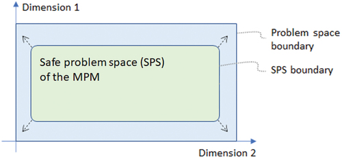
To tackle this issue, the output of the MPM can be adjusted by a correction model, as described above. Since the deviation parameter d, which provides the most information to the CM so as to predict the adjustment parameters, is centered around the value of 1, the problem space of the CM is unbounded. For the purpose of efficient training, the deviation parameter can be centered around 0 rather than 1. As a result of this strategy, the failure rate of the MPM is reduced to effectively zero since the CM is able to correctly adjust the Lamé curve parameters every time.
The correction model can also be implemented as a feedforward ANN having the following architecture: 5 input and 2 output floating point numbers; 2 hidden layers with 16 and 8 neurons, respectively, and the tanh activation function. The training data of the CM need not be standardized or normalized because the inputs and outputs of the HPP model are already normalized. Therefore, both the inputs and the outputs of the CM will be within the interval (−1, 1).
3.4.4. Collision monitoring and waiting
Collision monitoring (CM) is performed continuously during the motion. To this end, the positions of the host robot joints are used to generate a Catmull-Rom curve having 20 points and a bounding box is computed around each guest robot or the simulated human arms. If any of the points of the guest robot lies within any of the bounding boxes around the guests, a potential collision is detected. In this case, the host robot stops and waits for the guest to move away before resuming the motion. In host-guest scenarios, the programmer has to ensure that potential collisions do not lead to deadlocks or collisions of the guest robot(s) with the waiting host robot. Although technically it is possible to activate collision monitoring for the guest robot as well, the purpose of the guest-host configuration is to also allow (novice) robot programmers to experiment different collision scenarios in which at least one of the robots does not use software-based collision monitoring. The same purpose is also pursuit in the case of human-robot configurations. A stable configuration will ensure that the host robot will not collide with the guest robots of human hands. The Assembly tool aids programmers in creating and testing safe configurations for robots of different sizes. In general, larger robots should be designated as hosts because they can more easily avoid collisions with smaller robots than the other way around. To prevent unexpected collision situations, the programmer has the following options:
– Adapt the layout of the robotic station, notably the distance between robots and humans, and their orientation. To this end, the human-robot interaction configurations known from the literature, e.g. (Mukherjee et al. Citation2022) can be considered in multi-robot scenarios as well. In so doing, the guest robot(s) can be regarded as necessitating protection by the host robot. If the layout of the station foresees for the guest and host robots to work very closely together, then it might not be possible to avoid collisions between the robots using a curve-based motion planning algorithm. In such cases, a slower but complete motion planner should be considered (e.g. from the RRT family). At the same time, the programmer should weigh in the loss in productivity caused by using a slower planner, since the problem might be solved by increasing the distance between the robots. Hence, the layout of the assembly station is an important aspect to be considered in multi-robot programming, and the Assembly tool provides support for such considerations.
– If an application specifically required the guest and host robots to be placed very close to each other, then the programmer can use the inter-robot messaging actors ‘send signal’ and ‘await signal’. These actors can be used to create spatial mutual exclusion zone by means of having either of the robots way for a signal from another robot before resuming operation.
4. Evaluation
In this section, an evaluation of the tool based on one human – robot collaboration and one robot-robot collaboration scenario in manufacturing is presented. For each application, the results of a performance evaluation of the collision-free path planner and a discussion of Assembly’s simulation capabilities are presented.
4.1. Application scenarios
4.1.1. Human-robot collaboration
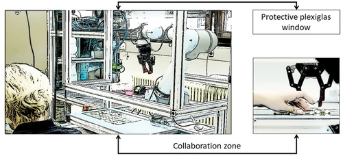
We consider a human – robot collaboration scenario that is often encountered in small and medium part assembly (Robotiq and Bayerdynamic Citation2022). Behind a Plexiglas window, a collaborative UR5 robot is operated. The Plexiglas window has an opening in its lower part that allows the human worker to manipulate the same work pieces as a UR5 cobot (). The height of the opening can be adapted to the current worker. Its goal is to protect the worker’s upper body while allowing maximal arm movement within the robot’s area and higher cobot speeds. In this scenario, the challenge is represented by the demand to maximize the cobot’s operational speed while keeping the risk of injury for the workers to a certifiable minimum.
Figure 10. Human–robot collaboration (HRC) application from bayerdynamic® (Robotiq and Baserdynamic, Citation2022).
illustrates the simulated bayerdynamic® scenario. The human arms are projected into the workspace of the simulated UR5 robot from another Assembly browser window in which the user can configure the position, orientation, and scale of the arms. The actual movements of the arms are performed according to a preset motion scheme, containing 10 different poses of the arms, as it is common in the computer animation field. The pose of the arms is defined by six points corresponding to the shoulder, elbow, and wrist of both arms. In Assembly, these positions can be defined by the programmer in the browser’s console, which is a component of the development tools provided by any modern web browser, by redefining an array of poses of the following form:
Figure 11. Simulated human-robot collaboration application scenario from bayerdynamic®.
var human_arms = [
[[8,0,-3],[4,-1,-3],[0,1,0],[0,5,0],[4,7,-3],[8,6,-3]],
[[8,1,-3],[4,-1,-3],[0,1,0],[0,5,0],[4,7,-3],[8,5,-3]],
//more points here
];
The rendering of the arms is updated at a frequency of 10 Hz and the animation loops through the list of poses provided by the user. To slow down the animation, some poses can be repeated. To accelerate the motion, the different poses can be defined further apart from each other.
illustrates the motion sequence required to pick and place the blue cube from one side of the work area to the other. The cube is automatically placed at a random position on the table, as a worker would likely place a finished work piece. At the same time, the arms are moving as the worker performs some assembly process steps independently from the robot. In other words, the workflow of the robot and that of the human are loosely coupled but the two operate in the same collaborative area. This setting can, for example, be one in which the robot recognizes a finished work part and picks it up to place it in a storage automatically, without disturbing the worker.
Figure 12. Movement sequence for picking and placing the blue cube in the human-robot collaboration region in the context of the bayerdynamic® scenario.
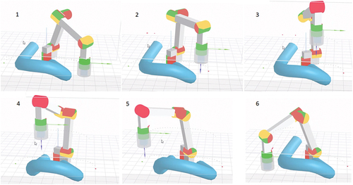
As shown in video 1 (Video 1 Citation2022), the robot successfully avoids collision with the human arms while picking and placing the blue cube from one side of the workspace to the other. When the direct path from origin to target only crosses one of the arms, the arms are independently regarded as obstacles one after the other. If the direct path crosses both arms, the obstacle detection algorithm treats both arms as a single obstacle. In a second video (Video 2 Citation2022), the cube is placed between the two arms. This demonstrates the flexibility of the planning with respect to the obstacles that can be detected and avoided (i.e. one or both arms). A third video (Video 3 Citation2022) illustrates a scenario in which the robot, after picking the cube from one side of the arms, first places the cube between the arms and then on the other side of them. These three videos arguably demonstrate the flexibility of the motion planner, which works regardless of the position and number of registered obstacles.
The runtime performance of the dynamic collision-free motion planner introduced in this paper are compared to those of the Adaptive Simplex Motion Planner (ASMP) from (Ionescu Citation2021a), which has been shown to outperform other machine learning-based dynamic planners. The planning approach described earlier in this paper improves the ASTP by introducing a correction model, which eliminates the need for executing a slower backup planner in the cases in which the fast machine learning based planner fails. The present approach is therefore called Corrected Adaptive Simplex Motion Planner (CASMP).
Planning time, path smoothness, and length were measured based on 50 robot trajectories between the defined origin and target points. The average planning time, tp, is represented by the average time that is required to predict the Lamé curve parameters for one planning cycle (i.e. one execution of the planner). During each run, the planner executes 100 times to account for the current position of the moving obstacle. The planning time is therefore independent from the trajectory length.
The path factor introduced in (Ionescu Citation2021a) was computed to account for the increase in path length due to the need to avoid the dynamic obstacle. The path factor is defined by pf = L/Lmin, with L being the obstacle avoiding toolpath length. Lmin is computed as the sum of the direct paths from origin to the first intersection point, from the first to the second intersection point, and from the second intersection point to the target. Lmin thus represents the shortest collision-avoiding path, which cannot be used in practice because it does not provide a buffer that allows the motion planner to react to the obstacle’s changing positions.
The smoothness factor introduced in (Ruiz et al. Citation2020) was used to account for the smoothness of the toolpath. Between the toolpath origin and target, the Lamé curve parameters are computed one hundred times. The toolpath thus represents a linear approximation of a Lamé curve arc defined by 100 intermediary waypoints. In general, the more waypoints, the more replanning is required and the smoother the toolpath. Depending on the obstacle’s current position and its dynamicity (i. e. rotation and translation speed), the toolpath switches continuously from one curve trajectory to another. These trajectories can also be thought of as orbits around the moving obstacle. If two subsequently computed Lamé curve parameters differ significantly, the robot’s toolpath will visibly ‘jump’ from one orbit to another. These jumps contribute to the smoothness factor, which is smaller when the path is smoother. The smoothness factor (sf) is thus given by the summed up angles (in radians) between any two sequential toolpath segments, divided by the respective segment’s length.
The planner failure rate (fr) is measured as the percentage of planning cycles which required the use of the slower but exact secondary planning model.
shows the performances of the planning algorithm in the context of this application. The test was conducted for the scenario illustrated in video 1 [ref]. The results show that CASMP is 3.3 time faster than ASMP, the latter of which has a 1.2% failure rate. This is because CASMP does not need to execute the hand-coded combinatorial algorithm in the cases in which the primary planning model fails the acceptance test. Instead, CASMP only runs the correction model, which is just as fast as the scoring the primary planner model. This comes at the cost of a slightly worsened path factor of CASMP compared to ASMP. At the same time, CASMP slightly improves the smoothness factor over ASMP.
Table 1. Results of the performance evaluation for the human-robot collaboration scenario.
The results suggest that the correction model of the CASMP has a significant impact on the planning speed even if the ASMP only has a relatively small failure rate of about 1%.
4.2.2. Robot-robot collaboration
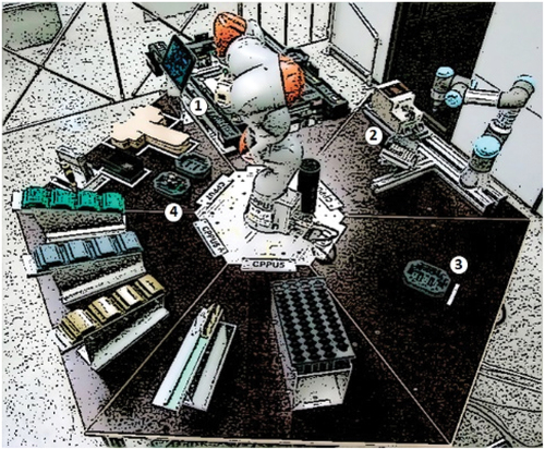
A multi-robot assembly cell consisting of a KUKA iiwa and a UR3 robot is considered for the evaluation of the robot-robot scenario (). The two robots work close to each other to implement several collaborative assembly process steps. The larger KUKA picks and holds a work piece for the smaller robot to screw in one screw. Then the KUKA robot places the finished part into a designated quality check jig. Meanwhile the UR3 robot picks up another screw and waits for the KUKA robot to provide a new part. The process is sketched in .
Figure 13. Siemens CPPS (Mert Citation2018; Schmidbauer et al. Citation2020). A KUKA iiwa and a UR3 collaborative robot are fixed on one of the sides of a hexagonal workbench. (1) the conveyor provides unfinished parts, and the KUKA robot performs and assembly step before transporting the work piece to a designated assembly jig (2). Here, the UR3 robot screws in the case and the KUKA robot transports the product for inspection (3). Finally, the KUKA robot places the finished part into a boxing jig (4), where a human worker performs the packaging.
In the real application, which is described in more details in (Schmidbauer et al. Citation2020), the KUKA robot uses a an RRT-based path planner, which requires several seconds to compute a complete trajectory of the robot depending on the obstacles from the environment. The RRT planner is thus not suitable for dynamic path planning in a productive environment because it would not be able to plan the motion while taking into consideration the moving UR3 robot. Hence the UR3 robot had to be placed out of the way of the KUKA robot.
The fact that just one of the triangles of the hexagonal assembly station is collaborative (i.e. the one foreseen for the packaging of the finished product) represents another restriction of the current application. Since the screw feeder frequently clogs, it would be preferrable to convert the UR3 robot’s triangle into a collaborative area where a human can check to see if the screw feeder is jammed and to restock the screw container while the robots are working. In order to accomplish this, the UR3 robot can be positioned closer to the hexagon’s center in order not to periclitated the worker, while allowing access to the screw feeder from the respective side.
How can the assembly cell’s throughput be enhanced while retaining the safety of human-robot collaboration, according to these two limitations?
The Assembly tool is used to simulate the answer to this question in the next subsection.
Using a faster planning algorithm would enable the larger robot to complete other jobs while the smaller robot is working, which would boost the productivity of the assembly cell. The UR3 robot could also be positioned closer to the hexagon’s center to increase safety by lowering the possibility of accidents with nearby workers.
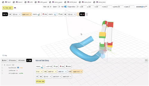
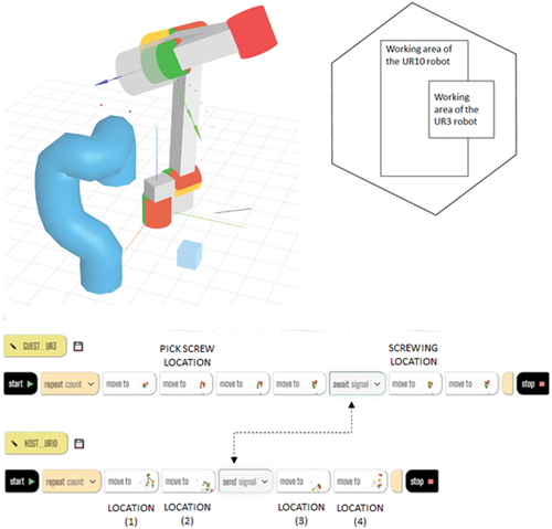
depicts a simulation of the Siemens CPPS scenario. Since Assembly only supports 6-DOF robot arms at the moment, a simulated UR10 robot was utilized in lieu of the KUKA iiwa robot. The UR3 robot was pulled farther from the hexagon’s edge by placing it closed to the larger robot. Thus, the operating space of the UR10 and UR3 robots was limited to the hexagonal workbench. At the bottom of , the programs of the two robots are displayed. In the smaller robot’s program, which performs the screwing, two synchronizations are required between the two robots because the UR3 robot must wait for the UR10 robot to insert the workpiece into a screwing jig. A video illustrating the simulation of this scenario is available here (Video 4 Citation2022).
Figure 14. The simulated multi-robot scenario with corresponding programs.
A second video (Video 5 Citation2022) illustrates a configuration in which the UR10 robot works in close proximity to two UR3 guests. The application scenario is similar to that from the previous video, with the difference that now a second smaller robot is positioned on another side of the UR10 robot. This scenario demonstrates the collision-free dynamic toolpath planning capabilities of the CASMP in the presence of several moving obstacles (the guest robots).
shows the performance measurements for the two planners, ASMP and CASMP, for the multi-robot scenario from the second video. In this complex scenario with two moving obstacles centered in different locations, the ASMP has a failure rate of almost 5%. The failure rate indicates the number of planning cycles in which the primary neural network-based planner fails the acceptance test and the slower but exact motion planner needs to be executed. The correction model of the CASMP is able to reduce this failure rate to zero at the expense of slightly increased path and smoothness factors compared to ASMP. These increases are due to the fact that the correction model causes ‘jumps’ from one orbit to another, with the said orbits being farther apart from one another than in a case where the slower but exact planner is used. This deficit of the correction can be eliminated by retraining it with scenario-specific data. Overall, however, the CASMP is almost 10 times faster than ASMP in this scenario, which allows for very fast dynamic toolpath planning in scenarios with multiple guest robots.
Table 2. Results of the performance evaluation for the multi-robot simulation scenario.
4.2.3. Comparison with state of the art
In this section, the performances of the CASMP planner are compared with those of a recently published collision-free multi-robot motion planning approach called Multi-Robot Dynamic Fabrics – MRDF (Bakker et al. Citation2023). MRDF is designed for multi-robot pick-and-place scenarios that can be encountered in industries such as manufacturing, medicine, and agriculture. Therefore, it addresses the same application scenarios as CASMP.
RF builds on an existing fabric-based approach to motion planning called dynamic fabrics – DF (Spahn, Wisse, and Alonso-Mora Citation2023). DF is well suited for crowded environments thanks to its reactivity. This reactivity, however, makes DF prone to local minima, which is a major drawback in multi-robot scenarios due to the higher likelihood of deadlocks. MRDF aims to adapt DF for multi-robot close-proximity pick-and-place scenarios, in which each robot independently plans its motion while taking into consideration the other robots that compete over the same shared workspace. This setup is prone to deadlocks since each robot plans its own motion without knowing the motion plans of the other robots. To deal with deadlocks, Bakker et al. (Citation2023) propose an approach called rollout fabrics (RF) – an approach to forward simulate MRDF that allows for detecting future deadlocks. When such a potential deadlock is detected, it is resolved through a heuristic approach that detects deadlocks where at least two robots have average velocities along a prediction horizon that is below a detection threshold.
CASMP differs from MRDF in the way deadlocks are handled. CASMP relies on the ‘Send signal’ and ‘Await signal’ actors which enable communication between the different robots. This requires the programmer to plan for deadlocks in shared areas by scheduling some robots to stop motion until the other robots have performed their motion in a shared area that is particularly prone to deadlocks. Also, CASMP primarily targets scenarios in which a larger robot works together with smaller robots, such that only the larger robot needs to dynamically replan its motion while accounting for the smaller robots. However, in its horizontal configuration, CASMP also allows for two or more robots to plan their motion independently, whereby deadlocks are resolved through a simple protocol of rank-based waiting: When a potential deadlock is detected, the lower-rank robot wait for the higher rank robots to move around them before resuming motion.
In the evaluation scenario involving only one UR3 guest robot and one UR10 host robot, a simple deadlock avoidance protocol was defined with the following constraints:
Only the host checks for collisions with the guest. When a potential collision is detected with a conservative buffer, the guest robot is instructed to wait as long as the collision warning is upheld. Meanwhile, the host robot continues moving.
The host robot also checks whether its next waypoint falls within the current bounding box of the guest robot. If that is the case, the host robot waits for a predefined amount of time and if the conditions to continue moving to the next target are not met (e.g. due to a potential collision), it drops the respective waypoint and attempts to reach the next one.
Using this protocol, deadlocks are avoided because the host robot always continues to move. Collisions are also avoided thanks to the conservative buffer required by constraint a. It is noteworthy that when the collision buffer is sufficiently large, collisions can be successfully avoided while allowing the robots to work in overlapping regions of the shared workspace.
provides a comparison of key performance indicators of CASMP a host-guest collaboration scenario, and those of MRDF as reported in (Bakker et al. Citation2023). Video 6 illustrates the test scenario in which both robots are supposed to pick a cube from approximately the same overlapping region and place it somewhere else, whereby the larger one of the two robots avoids collisions with the smaller robot (Video 6 Citation2023). The measure of success for CASMP is defined as the percentage of waypoints that are reached while applying constraint b., the task being to pick and place a cube from and to positions that are outside the guest robot’s working area. The success rate for MRDF is defined as ‘[t]he ratio of successfully grasped and placed cubes within the time window Tmax over the total number of cube’ (Bakker et al. Citation2023). Following (Bakker et al. Citation2023), the collision rate is defined for all planners as the ratio of scenarios where at least one collision occurred. In the case of MRDF, collisions of one or more of the robots´ bounding spheres with another robot or the environment is registered. In the case of CASMP, a collision is registered when the host robot collides with the covering tube of the guest robot while taking into consideration that the covering tube also provides a collision buffer of about 10% of its width compared to the size of the guest robot. That is, not every apparent contact between the two robots immediately leads to a collision. The planning time is defined for all planners as the time required to compute a new motion plan. In the case of CASMP, the results were computed for 100 pick and place cycles, where the pick and place positions were the same.
Table 3. Comparison of key performance indicators of ASMP, CASMP, and MRDF (with and without RF).
The result show that the MRDF-FR planner has the best success rate and the lowest collision rate. However, its planning time is much higher than that of CASMP and MRDF. In the case of CASMP, the collision and success rate depend of the choices of the buffers and may differ from one scenario to another. In the tested scenario, the collision buffer according to constraint a. was defined to be twice as large as the target overlap buffer according to b. (i.e. 2 units vs. 1). This ratio ensures a relatively low collision rate when the robots operate very close one to another. Also, each scenario would likely benefit from different configurations for the two buffers. For example, if the robots do not operate so close to one another, the collision buffer can be set to a higher value. However, if the two robots are very close to each other, a high collision buffer leads to more deadlocks.
Although the results of the planners are comparable, it is noted that the MRDF and MRDF-FR planners only require the robots to communicate their current configuration, velocity, and goal information with the other robots. By contrast, with CASMP, the host robot instructs the guest robot when to wait and how long, and the host robot is aware of the guest robot’s pose at all times. While reducing the communication needs of the robots is important for highly autonomous scenarios, in manufacturing applications such a reduction in communication would not be of great advantage since the pose of each robot can be easily known and communicated to other robots, which actually provides a major source of information that should not be ignored. When leveraging that information, the planning protocols and algorithms can be simple and deterministic.
4.2.4. Limitations
The simulation capabilities of Assembly are currently limited to only one human arms model and two guest robots. The limitation to only two guest robots is due to performance reasons.
The CASMP is an opportunistic toolpath planner, which deals with imminent collisions with other elements of the robot by simply stopping the motion and waiting for the obstacle to move away. Although in practical scenarios, due to its high replanning frequency of over 3500 Hz (i.e. considering that a single planning cycle requires less than 0.3 ms), this strategy proves to be sufficient in the case of dynamic obstacles, future version of the planner could also leverage a rollback strategy to one of the previous poses along the motion trajectory.
5. Conclusion
This paper introduced features designed to enable the programming and simulation of multiple robots and human arms in Assembly for robot-robot and human-robot collaboration scenarios. To enable useful and efficient multi-robot simulation, an improved dynamic, collision-free toolpath planning algorithm, called Corrected Adaptive Simplex Motion Planner (CASMP), was developed.
Assembly emphasized the algorithmic aspects of multi-robot programming rather than realistic robot rendering techniques. This saves development time, which makes the tool easily adaptable to the state of the art in robot programming and simulation. The philosophy of this approach was termed ‘frugal simulation,’ which reflects a pragmatic mindset focused on experimenting with machine learning and novel rendering techniques without the need of resource intensive robot software frameworks like ROS and Unity.
The corrective motion planner implemented in Assembly improves over the Adaptive Simplex Motion Planner (ASMP) by using a second neural network model, which corrects the output of the primary neural network toolpath planner instead of executing a slower but exact combinatorial optimization algorithm when the primary planner fails the acceptance test. This approach enables a speed-up of up to 10 times in complex multi-robot scenarios. The open-source Assembly simulation tool allows users to further improve the CASMP and to adapt it to their own purposes.
The democratization of robot and cobot technologies is facilitated by web-based simulation and programming tools, such as Assembly. As opposed to existing robot programming and simulation frameworks, which requires considerable levels of expertise to configure and program, Assembly only requires a web browser and computational thinking abilities. In combination with the code generation features described in (Ionescu, Citation2021b), the tool can be used for generic robot programming in (non)industrial contexts. Assembly is being successfully used in online and face-to-face teaching, is completely free and is available online at: https://assembly.comemak.at.
Disclosure statement
No potential conflict of interest was reported by the author(s).
Additional information
Funding
References
- Aivaliotis, S., K. Lotsaris, C. Gkournelos, N. Fourtakas, S. Koukas, N. Kousi, and S. Makris. 2023. “An Augmented Reality Software Suite Enabling Seamless Human Robot Interaction.” International Journal of Computer Integrated Manufacturing 36 (1): 3–29. https://doi.org/10.1080/0951192X.2022.2104459.
- Bakker, S., L. Knoedler, M. Spahn, W. Böhmer, and J. Alonso-Mora. 2023. “Multi-Robot Local Motion Planning Using Dynamic Optimization Fabrics.” arXiv preprint arXiv:2310.12816. https://info.arxiv.org/help/faq/references.html.
- Beck, M. 2021. “Glumb Robot Simualtoir.” Acccessed 15 10 2021. https://github.com/glumb.
- Bravo, F. A., A. M. González, and E. González. 2017. “A Review of Intuitive Robot Programming Environments for Educational Purposes.” In 2017 IEEE 3rd Colombian Conference on Automatic Control, Cartagena, Columbia, 1–6. IEEE.
- Catmull, E., and R. Rom. 1974. “A Class of Local Interpolating Splines.” In Computer Aided Geometric Design, edited by R. E. Barnhill and R. F. Reisenfeld, 317–326. New York: Academic Press.
- Chen, W., H. Fang, Y. Yang, and W.He 2017 July, 21–23. “Optimal Trajectory Planning for Delta Robot Based on Three-Parameter Lamé Curve.” In Proceedings of the 2nd International Conference on Cybernetics, Robotics and Control (CRC), Chengdu, China, 39–44.
- Cimurs, R., J. H. Lee, and I. H. Suh. 2020. “Goal-Oriented Obstacle Avoidance with Deep Reinforcement Learning in Continuous Action Space.” Electronics 9 (3): 411. https://doi.org/10.3390/electronics9030411.
- De Schepper, D., G. Schouterden, K. Kellens, and E. Demeester. 2023. “Human-Robot Mobile Co-Manipulation of Flexible Objects by Fusing Wrench and Skeleton Tracking Data.” International Journal of Computer Integrated Manufacturing 36 (1): 30–50.
- drag and bot GmbH. 2020. “Flexible Produktionsplanung dank einfacher Roboterprogrammierung.” JOT Journal für Oberflächentechnik 60 (5–6): 32–33. https://doi.org/10.1007/s35144-020-0550-2.
- Elhoseny, M., A. Tharwat, and A. E. Hassanien. 2018. “Bezier Curve Based Path Planning in a Dynamic Field Using Modified Genetic Algorithm.” Journal of Computational Science 25:339–350. https://doi.org/10.1016/j.jocs.2017.08.004.
- Franka Emika. 2021. “Franka Emika Desk.” Accessed October 15, 2021. https://www.franka.de/.
- Ge, J., F. Sun, and C. Liu RRT-GD: An Efficient Rapidly-Exploring Random Tree Approach with Goal Directionality for Redundant Manipulator Path Planning. In Proceedings of the IEEE International Conference on Robotics and Biomimetics, Qingdao, China, 3–7 December 2017, 1983–1988.
- Halt, L., F. Nagele, P. Tenbrock, and A. Pott, 2018. “Intuitive Constraint-Based Robot Programming for Robotic Assembly Tasks* the Research Leading to These Results Has Received Funding from the European Unions Seventh Framework Programme FP7/2013-2017 Under Grant Agreement N 608604 (LIAA: Lean Intelligent Assembly Automation) and Horizon 2020 Research and Innovation Programme Under Grant Agreement N 688642 (RAMPup).” In Proceedings of the 2018 IEEE International Conference on Robotics and Automation (ICRA). Presented at the 2018 IEEE International Conference on Robotics and Automation (ICRA), 520–526. https://doi.org/10.1109/ICRA.2018.8462882
- Han, L., H. Yashiro, H. T. N. Nejad, Q. H. Do, and S. Mita.2010 June, 21–.14 “Bézier Curve Based Path Planning for Autonomous Vehicle in Urban Environment.” In Proceedings of the 2010 IEEE Intelligent Vehicles Symposium, San Diego, CA, USA, 1036–1042.
- Hornung, A., M. Neubauer, and L. Müller. 2022. U.S. Patent No. 11,512,940. Washington, DC: U.S. Patent and Trademark Office.
- Huang, Y., J. Silvério, L. Rozo, and D. G. Caldwell. 2018. “Generalized task-parameterized skill learning.” In Proceedings of the 2018 IEEE international conference on robotics and automation (ICRA), Brisbane, Australia, 5667–5474. IEEE.
- Ionescu and Fröhlich. 2022. “Computer-Implemented Method for Correcting at Least One Model Output of a First Trained Machine Learning Model.” International Patent Application WO2023131444A1. Geneva, Switzerland: The World Intellectual Property Organization (WIPO).
- Ionescu, T. B. 2020. “Meet Your Personal Cobot, but Don’t Touch It Just Yet.” In Proceedings of the 2020 29th IEEE International Conference on Robot and Human Interactive Communication (RO-MAN), Naples, Italy, 1113–1118. IEEE.
- Ionescu, T. B. 2021a. “Adaptive Simplex Architecture for Safe, Real-Time Robot Path Planning.” Sensors 21 (8): 2589. https://doi.org/10.3390/s21082589.
- Ionescu, T. B. 2021b. “Leveraging Graphical User Interface Automation for Generic Robot Programming.” Robotics 10 (1): 3. https://doi.org/10.3390/robotics10010003.
- Ionescu, T. B., and S. Schlund. 2021. “Programming Cobots by Voice: A Human-Centered, Web-Based Approach.” Procedia CIRP 97:123–129. https://doi.org/10.1016/j.procir.2020.05.213.
- Ionescu, T. B., and S. Schlund. 2019. “A Participatory Programming Model for Democratizing Cobot Technology in Public and Industrial Fablabs.” Procedia CIRP 81:93–98. https://doi.org/10.1016/j.procir.2019.03.017.
- Jia, Y., Y. Li, B. Xin, and C. Chen. 2020. Path Planning with Autonomous Obstacle Avoidance Using Reinforcement Learning for Six-Axis Arms. In Proceedings of the 17th IEEE International Conference on Networking, Sensing and Control (ICNSC), Nanjing, China, October 30 – November 2, 1–6.
- Ji, M., L. Zhang, and S. Wang. 2019. A Path Planning Approach Based on Q-Learning for Robot Arm. In Proceedings of the 3rd International Conference on Robotics and Automation Sciences (ICRAS), Wuhan, China, June 1–3, 15–19.
- Krämer, M., C. Rösmann, F. Hoffmann, and T. Bertram. 2020. “Model Predictive Control of a Collaborative Manipulator Considering Dynamic Obstacles.” Optimal Control Applications & Methods 41 (4): 1211–1232. https://doi.org/10.1002/oca.2599.
- Larsen, L., and J. Kim. 2021. “Path Planning of Cooperating Industrial Robots Using Evolutionary Algorithms.” Robotics and Computer-Integrated Manufacturing 67:102053. https://doi.org/10.1016/j.rcim.2020.102053.
- Larsen, L., A. Schuster, J. Kim, and M. Kupke. 2018. “Path Planning of Cooperating Industrial Robots Using Evolutionary Algorithms.” Procedia Manufacturing 17:286–293. https://doi.org/10.1016/j.promfg.2018.10.048.
- LaValle, S. M., and J. Kuffner Jr. 2001. “Randomized Kinodynamic Planning.” The International Journal of Robotics Research 20 (5): 378–400. https://doi.org/10.1177/02783640122067453.
- Lavalle, S. M., and J. J. Kuffner. 2000. “Rapidly-Exploring Random Trees: Progress and Prospects.” In Algorithmic and Computational Robotics New Directions, edited by Bruce Donald, Kevin Lynch and Daniela Rus, 293–308. Boca Raton, FL, USA: CRC Press.
- McCool, M. D. 2000. “Shadow Volume Reconstruction from Depth Maps.” ACM Transactions on Graphics (TOG) 19 (1): 1–26. https://doi.org/10.1145/343002.343006.
- Mert, W. 2018. “Autonome individualisierte Produktion. hi!tech - Siemens innovation magauone 01/2018.” Accessed October 15, 2021. https://hitech.at/sites/default/files/magazin/1801hitech-ebook-1.pdf.
- Miura, J. Support Vector Path Planning. In Proceedings of the IEEE/RSJ International Conference on Intelligent Robots and Systems, Beijing, China, 9–15 October 2006, 2894–2899.
- Mukherjee, D., K. Gupta, L. H. Chang, and H. Najjaran. 2022. “A Survey of Robot Learning Strategies for Human-Robot Collaboration in Industrial Settings.” Robotics and Computer-Integrated Manufacturing 73:102231. https://doi.org/10.1016/j.rcim.2021.102231.
- Otte, M. W. 2015. A Survey of Machine Learning Approaches to Robotic Path-Planning. Boulder, CO, USA: University of Colorado at Boulder.
- Otte, S., L. Hofmaier, and M. V. 2018, October 4–7 Butz Integrative Collision Avoidance within RNN-Driven Many-Joint Robot Arms. In Proceedings of the 27th International Conference on Artificial Neural Networks, Rhodes, Greece, 748–758.
- Pires, J. N., and A. S. Azar. 2018. “Advances in Robotics for Additive/Hybrid Manufacturing: Robot Control, Speech Interface and Path Planning.” Industrial Robot: An International Journal 45 (3): 311–327. https://doi.org/10.1108/IR-01-2018-0017.
- Prianto, E., M. Kim, J.-H. Park, J.-H. Bae, and J.-S. Kim. 2020. “Path Planning for Multi-Arm Manipulators Using Deep Reinforcement Learning: Soft Actor–Critic with Hindsight Experience Replay.” Sensors 20 : 5911. https://doi.org/10.3390/s20205911.
- Robotiq, and Bayerdynamic. 2022. Bayerdynamic Scenario. Available online: https://robotiq.com/resource-center/case-studies/doubled-production-on-limited-floor-space (accessed on 1 February).
- Robotiq and Bayerdynamic. Accessed November 26, 2022. https://robotiq.com/resource-center/case-studies/doubled-production-on-limited-floor-space.
- Ruiz, S. G., L. V. Calderita, A. Hidalgo-Paniagua, and J. P. B. Rubio. 2020. “Measuring Smoothness as a Factor for Efficient and Socially Accepted Robot Motion.” Sensors 20 (23): 6822. https://doi.org/10.3390/s20236822.
- Schäfer, P. M., F. Steinmetz, S. Schneyer, T. Bachmann, T. Eiband, F. S. Lay, and K. Nottensteiner. 2021, September. “Flexible Robotic Assembly Based on Ontological Representation of Tasks, Skills, and Resources.” In Proceedings of the International Conference on Principles of Knowledge Representation and Reasoning, 18 ( 1): 702–706.
- Schmidbauer, C., S. Schlund, T. B. Ionescu, and B. Hader. 2020. “Adaptive Task Sharing in Human-Robot Interaction in Assembly.” In Proceedings of the 2020 IEEE International Conference on Industrial Engineering and Engineering Management (IEEM), Singapore, 546–550. IEEE.
- Seals, C., M. B. Rosson, J. M. Carroll, T. Lewis, and L. Colson. 2002, September. “Fun Learning Stagecast Creator: An Exercise in Minimalism and Collaboration.” In Proceedings of the IEEE 2002 Symposia on Human Centric Computing Languages and Environments, Arlington, VA, USA, 177–186. IEEE.
- Seo, D. J., N. Y. Ko, and R. G. Simmons. 2009. “An Elastic Force Based Collision Avoidance Method and Its Application to Motion Coordination of Multiple Robots.” International Journal of Computer Integrated Manufacturing 22 (8): 784–798. https://doi.org/10.1080/09511920902741083.
- Shimizu, M., K. Kobayashi, and K. Watanabe Clothoidal Curve-Based Path Generation for an Autonomous Mobile Robot. In Proceedings of the SICE-ICASE International Joint Conference, Busan, Korea, 18–21 October 2006, 478–481.
- Shome, R., K. Solovey, A. Dobson, D. Halperin, and K. E. Bekris. 2020. “Drrt*: Scalable and Informed Asymptotically-Optimal Multi-Robot Motion Planning.” Autonomous Robots 44 (3–4): 443–467. https://doi.org/10.1007/s10514-019-09832-9.
- Spahn, M., M. Wisse, and J. Alonso-Mora. 2023. “Dynamic Optimization Fabrics for Motion Generation.” IEEE Transactions on Robotics 39 (4): 2684–2699. https://doi.org/10.1109/TRO.2023.3255587.
- Steinmetz, F., V. Nitsch, and F. Stulp. 2019. “Intuitive Task-Level Programming by Demonstration Through Semantic Skill Recognition.” IEEE Robotics and Automation Letters 4 (4): 3742–3749. https://doi.org/10.1109/LRA.2019.2928782.
- Steinmetz, F., A. Wollschläger, and R. Weitschat. 2018a. “Razer—a hri for visual task-level programming and intuitive skill parameterization.” IEEE Robotics and Automation Letters 3 (3): 1362–1369. https://doi.org/10.1109/LRA.2018.2798300.
- Tai, L., S. Li, and M. Liu A Deep-Network Solution Towards Model-Less Obstacle Avoidance. In Proceedings of the EEE/RSJ International Conference on Intelligent Robots and Systems (IROS), Daejeon, Korea, 9–14 October 2016, 2759–2764.
- Tai, L., G. Paolo, and M. Liu Virtual-to-real deep reinforcement learning: Continuous control of mobile robots for mapless navigation. In Proceedings of the IEEE/RSJ International Conference on Intelligent Robots and Systems (IROS), Vancouver, BC, Canada, 24–28 September 2017, 31–36.
- Thomsen, M. R., P. Nicholas, M. Tamke, S. Gatz, Y. Sinke, and G. Rossi. 2020. “Towards Machine Learning for Architectural Fabrication in the Age of Industry 4.0.” International Journal of Architectural Computing 18 (4): 335–352. https://doi.org/10.1177/1478077120948000.
- Tsarouchi, P., S. Makris, and G. Chryssolouris. 2016. “Human–Robot Interaction Review and Challenges on Task Planning and Programming.” International Journal of Computer Integrated Manufacturing 29 (8): 916–931. https://doi.org/10.1080/0951192X.2015.1130251.
- Video 1. 2022. https://assembly.comemak.at/videos/video%20hrc1.mp4.
- Video 2. 2022. https://assembly.comemak.at/videos/video%20hrc2.mp4.
- Video 3. 2022. https://assembly.comemak.at/videos/video%20hrc3.mp4.
- Video 4. 2022. https://assembly.comemak.at/videos/video%20rrc1.mp4.
- Video 5. 2022. https://assembly.comemak.at/videos/video%20rrc2.mp4.
- Video 6. 2023. https://assembly.comemak.at/videos/video%20rrc3.mp4.
- Villarrubia, G., J. F. De Paz, P. Chamoso, and F. De la Prieta. 2018. “Artificial Neural Networks Used in Optimization Problems.” Neurocomputing 272:10–16. https://doi.org/10.1016/j.neucom.2017.04.075.
- Wang, Y., H. He, and C. Sun. 2018. “Learning to Navigate Through Complex Dynamic Environment with Modular Deep Reinforcement Learning.” IEEE Transactions on Games 10 (4): 400–412. https://doi.org/10.1109/TG.2018.2849942.
- Weintrop, D., A. Afzal, J. Salac, P. Francis, B. Li, D. C. Shepherd, and D. Franklin. 2018, April. Evaluating CoBlox: A comparative study of robotics programming environments for adult novices. In Proceedings of the 2018 CHI Conference on Human Factors in Computing Systems, Montreal, Canada, 1–12.
- Wei, K., and B. Ren. 2018. “A Method on Dynamic Path Planning for Robotic Manipulator Autonomous Obstacle Avoidance Based on an Improved RRT Algorithm.” Sensors 18 (2): 571. https://doi.org/10.3390/s18020571.
- Wildgrube, F., A. Perzylo, M. Rickert, and A. Knoll, 2019. Semantic Mates: Intuitive Geometric Constraints for Efficient Assembly Specifications, In Proceedings of the 2019 IEEE/RSJ International Conference on Intelligent Robots and Systems (IROS). Presented at the 2019 IEEE/RSJ International Conference on Intelligent Robots and Systems (IROS), 6180–6187. https://doi.org/10.1109/IROS40897.2019.8968041
- Wong, C. C., S. Y. Chien, H. M. Feng, and H. Aoyama. 2021. “Motion Planning for Dual-Arm Robot Based on Soft Ac-Tor-Critic.” IEEE Access 2021 9:26871–26885. https://doi.org/10.1109/ACCESS.2021.3056903.
- Xie, Z., D. Shang, and P. Ren. 2015. “Optimization and Experimental Verification of Pick-And-Place Trajectory for a Delta Parallel Robot Based on Lamé Curves.” Journal of Mechanical Engineering 51 (1): 52–59. https://doi.org/10.3901/JME.2015.01.052.
- Xie, Z., P. Wu, and P. Ren 2016, August A Comparative Study on the Pick-and-Place Trajectories for a Delta Robot. In Proceedings of the International Design Engineering Technical Conference & Computers and Information in Engineering, Charlotte, NC, USA, 21–24.
- Zhang, X., and Z. Ming. 2019. “Trajectory Planning and Optimization for a Par4 Parallel Robot Based on Energy Consumption.” Applied Science 9 (13): 2770. https://doi.org/10.3390/app9132770.
- Zhu, Y., R. Mottaghi, E. Kolve, J. J. Lim, A. Gupta, L. Fei-Fei, and A. Farhadi. 2017. Target-driven visual navigation in indoor scenes using deep reinforcement learning. In Proceedings of the IEEE international conference on robotics and automation (ICRA), Singapore, 29 May – 3 June, 3357–3364.