
 ?Mathematical formulae have been encoded as MathML and are displayed in this HTML version using MathJax in order to improve their display. Uncheck the box to turn MathJax off. This feature requires Javascript. Click on a formula to zoom.
Abstract
Safety-critical cyber-physical systems (SC-CPS) have the characteristics of distributed, heterogeneous, strong coupling of computing resources and physical resources. With the increased acceptance of Model-Driven Development (MDD) in the safety-critical domain, the SysML language has been broadly used. Increasing complexity results in the formal verification of the SysML models of SC-CPS often faces the so-called state-explosion problem. Moreover, safety analysis is also an important step to ensure the quality of SC-CPS. Thus, this article proposes an integrated SysML modelling and verification approach to cover specification of nominal behaviour and safety. First, an extension of SysML is presented, in which the contract information (i.e. Assume and Guarantee) is extended for SysML block diagrams and a Safety Profile is proposed to describe safety-related concepts. Second, the transformation from SysML to the compositional verification tool OCRA is given. Third, the safety analysis is achieved by translating the Safety Profile model into FTA (Fault Tree Analysis). Finally, the prototype tools including SysML2OCRA and SafetyProfile2FTA are represented, and the effectiveness of the method proposed in this paper is verified through actual industrial cases.
1. Introduction
Safety-critical cyber-physical systems (SC-CPS) are complex systems often combining physical and mechanical components, networking and software (Mo et al., Citation2014; Varghese & Thampi, Citation2020). There are many well-known examples in different domains such as aircraft flight control, space missions, and nuclear systems. These systems are always designed with the properties such as high safety, high reliability, and strong real-time. Currently, Model-Driven Development (MDD) (Hause & Thom, Citation2007; Yu et al., Citation2020) is generally accepted as a key enabler for the design of SC-CPS. For example, in the guidance of civil avionics software certification DO-178C (Brosgol, Citation2011; DO-178C, Citation2011; Tim King & Bill Stclair, Citation2012), MDD (DO-331) (SC-205, Citation2011b) and formal methods (DO-333) (SC-205, Citation2011a) are considered as vital technology supplements.
There are several MDD languages and approaches covering various modelling demands, such as Unified Modeling Language (UML) for generic modelling, Systems Modeling Language (SysML) for system-level modelling (Stewart et al., Citation2017; Weilkiens, Citation2007; Zhang et al., Citation2020), Architecture Analysis and Design Language(AADL) (Sabaghian et al., Citation2020; Yang et al., Citation2014) for the architectural modelling and analysis of embedded systems, SCADE and Simulink for functional modelling, and Modelica for multi-disciplines modelling. SysML was designed by the International Council on Systems Engineering(INCOSE) and the Object Management Group (OMG). As a profile for UML2.0 (Group, Citation2007), SysML was created specifically for the systems engineering domain to integrate multiple views of large, complex systems engineering consisting of hardware, software, requirements, data, people and processes. Moreover, SysML provides several extension mechanisms such as stereotypes, diagram extensions, and model libraries. There are several commercial and open-source tools for SysML model creation and design, which include Rational Rhapsody, Modeler, Modelio, as well as Papyrus (Berumen-Flucker et al., Citation2019). They support model-based engineering and have been used successfully in industry to model complex systems. Thus, SysML is more and more considered as the system modelling language in the domain of SC-CPS.
The MDD of SC-CPS often contains two complementary processes. On the one side, hierarchical design refines a set of requirements into increasingly detailed levels, decomposing a system into subsystems, down to basic components. On the other side, the process of safety analysis (SA) evaluates the impact of faults. Therefore, an integrated development approach covering specification of nominal behaviour and safety is a challenging problem. In this article, we would like to propose an integrated SysML modelling and verification approach to cover specification of nominal behaviour and safety.
For the modelling, SysML can be used to describe models for various complex systems. For instance, the modelling elements of SysML, such as BDD (Block Definition Diagram), IBD (Internal Block Diagram), ACT (Activity Diagram), SMD (State Machine Diagram), and so on, are used to describe the nominal behaviour. However, it does not provide the necessary constructs to capture safety information in the system model. There are several recent works on the SysML extension with the capability to model safety information. Mhenni et al. (Citation2015) proposed an SysML safety extension relied on stereotypes that represent artefacts of an FMEA (Failure Mode Effects Analysis) such as failure modes, causal factors, system effects, probabilities, severities, recommended actions, detection methods, etc. They mainly focus on mechatronic systems. However, they have not given the analysis methods for the safety extension. Clegg et al. (Citation2019) present the progress in the setting of Rolls-Royce's UltraFan engine demonstrator development to provide SysML support to Fault Tree Analysis (FTA). Alshboul and Petriu (Citation2018) give an automatic derivation of fault tree models from SysML models for safety analysis. A small subset of SysML including BDD, IBD and SMD is considered in their transformation. In addition, the dependability extension of OMG's standard MARTE profile, called DAM profile, is used to describe the safety information of the SysML model. Based on the existing work, the OMG proposes the OMG standard for integrating safety and reliability analysis into MBSE: concepts and applications (Biggs et al., Citation2019). It discusses the proposed specification's use of generic concepts to allow information interchange amongst diverse analyses, its use of existing SysML constructs to provide automation of safety and reliability work in existing modelling tools, and describes several of the supported analysis methods. Moreover, it always needs adaptation to different domains through extensions to the standard profile. Compared with the existing work such as (Alshboul & Petriu, Citation2018; Clegg et al., Citation2019; Mhenni et al., Citation2015), we propose a “Safety Profile” of SysML, which is an adaption of the generic concepts of OMG standard safety extension for the aerospace domain, for instance, some concepts in the aerospace safety standard ARP 4761 (International, Citation1996) are considered.
For the verification and analysis of the SysML model, on one hand, model checking is a popular way to ensure the verification of SysML models. Ando et al. (Citation2013) proposed to formalise SysML state machines with CSP. Calvino and Apvrille (Citation2021) proposed a new model-checker that can be applied (almost) directly to the SysML model. Model checking is an automatic verification technique for hardware and software systems that are finite-state or have finite-state abstractions. As the number of state variables in the system increases, the size of the system state space grows exponentially. This phenomenon is commonly called the “State Explosion Problem”. The main technical challenge in the formal verification of SC-CPS is the state explosion which can occur if the system being verified has many components which make transitions in parallel. However, increasing complexity results in the formal verification of the SysML models of SC-CPS often faces the so-called state-explosion problem. An approach to deal with the state explosion problem is the use of contract-based compositional verification (Ahamad & Pathan, Citation2020) which leverages the structure of the system. The basic idea is to apply divide-and-conquer approaches to infer global properties of complex systems from properties of their components. On the other hand, we propose a method to generate fault tree from SysML safety model, which is described as the “Safety Profile”.
This article proposes an integrated SysML modelling and verification approach to covering specification of nominal behaviour and safety, where compositional verification is used to verify the nominal behaviour of the SysML model and FTA is used to do the safety analysis based on the “Safety Profile” of SysML. The main contributions are summarised as follows:
First, the model-driven design is integrated with the safety analysis process to provide a structured and consistent system model for safety engineering professionals, through SysML extensions. At the same time, the system designer can use the results of the FTA to enrich and adapt the system design. Thus, a communication bridge is built between systems engineering and safety engineering.
Second, an extension of SysML is presented in which contract information (i.e. assumptions and guarantees), that is to extend SysML block diagrams, and transformation rules from the extended SysML to the compositional verification tool OCRA are given. Automatic generation of OCRA system specifications can effectively maintain the properties of the original SysML model and reduce errors caused by manual authoring. These properties can also be maintained in the process of system refinement.
Third, a SysML safety profile for SC-CPS is proposed, which enables safety analysis by converting the safety profile model to FTA. The goal is to provide safety experts with structured and consistent modelling of the system to allow merging MDD and safety analysis processes. In return, system architect's modelling is enriched and adjusted with the result of any safety analyses carried out with FTA. Thus, a thorough consistency is established between systems engineering and safety analysis artefacts.
Finally, the prototype tools including SysML2OCRA and SafetyProfile2FTA are represented, and the effectiveness of the method proposed in this paper is verified through an industrial case study that is Guidance, Navigation and Control (GNC) system.
2. Background
In this section, we introduce the SysML language, contract-based compositional verification and the OCRA tool, and fault tree analysis.
2.1. Systems modelling language
Systems Modeling Language is a general architecture modelling language for system engineering applications (SysML-Forum, Citation2003). The extensions of SysML are designed to support systems engineering activities, to provide simple but powerful specification, analysis, design, verification and validation for a broad range of systems, and to support the effective modelling of capture, structure, behaviour, and allocation for system requirements as well as the constraints of system attributes.
The definition of SysML consists of semantics and representing notation. As SysML is extended from UML2.0, SysML defines its semantics with the metamodel. The metamodel can provide explicit semantics for all elements of SysML. SysML provides nine kinds of diagrams to describe the features of systems and describe the SysML model from different aspects.
A powerful feature of UML/SysML is the profile mechanism, which allows for extending existing model elements for a specific need, such as modelling domain-specific concepts. Profiles can be a way to model Domain Specific Languages (DSLs) based on UML, such as MARTE and DAM profiles.
SysML modelling tools include EnterpriseArchitect, MagicDraw, Eclipse Papyrus (Dubois et al., Citation2009), etc. Among them, Eclipse Papyrus is an industrial-grade model-based open source engineering tool, which supports UML and SysML modelling, and supports two language extension mechanisms. It is also the basic platform for a number of industrial modelling tools and has been successfully applied in industrial projects.
2.2. Contract-based compositional verification
Complex CPS systems are always hierarchically organised by using component-based architecture. Automatic formal verification techniques such as model-checking can help to analyse the behaviours of such systems. For instance, thanks to a model-checking tool, one can create a model and analyse all of the behaviours of the components in the architecture model. Actually, most of the time, the architecture model is flattened. Nevertheless, doing so, often faces the so-called state-explosion problem. An approach to deal with the state explosion problem is the use of compositional verification which leverages the structure of the system. In these techniques, the verification of a composite system is reduced to the verification of its parts.
A well-known compositional approach is based on assume/guarantee contracts (Gacek et al., Citation2015; Garavel et al., Citation2015) where each component is annotated with a contract consisting of an assumption specifying how the component expects its environment to behave, and a guarantee specifying the behaviour guaranteed by the component if the assumptions hold. The component implementations can be abstracted with contracts that specify the behavioural aspects that are relevant for the system-level properties. The main compositional verification methods and tools are AGREE (Liu et al., Citation2016) and OCRA (Othello Contracts Refinement Analysis) (Cimatti et al., Citation2013). Here we leverage compositional verification and assume-guarantee contracts to verify the safety properties of SC-CPS by using OCRA.
OCRA is a new tool that provides means for checking the refinement of contracts specified in a linear-time temporal logic. In addition, it provides a formal concept of contract correctness, which was simplified as checking the validity of a necessary-sufficient pair. The generated proof obligation is the same formula as the temporal logic used to express the contract, which can be determined by an appropriate decision-making procedure.
2.3. Fault tree analysis
Fault tree analysis (Lee et al., Citation2009) is a top-down, deductive failure analysis in which an undesired state of a system is analysed using Boolean logic to combine a series of lower-level events. It is a diagrammatical representation of different causes of system failure. The fault tree is used to identify and assess the compositional of the undesired events in the context of system operation and its environment that can lead to the undesired state of the system. It is recognised as an important tool for evaluating safety and reliability in system design, development and operation.
A Fault Tree is used to model the safety properties by setting the undesired system failure as a top event for the FT. The events that have been identified contributing to the occurrence of the top event are then combined using Boolean logic, which specifies how they lead to it. This process is performed for each of the events until basic events are reached. The fault tree is based on “Boolean” algebraic and probabilistic basis that relates probability calculations to “Boolean” logic functions. Whenever an adverse event occurs, you need to analyse its root cause with a fault tree analysis. Usually, it is a failure probability function determined by the composition of individual components as well as the architectural logic of the system. The primary analytical units in the fault tree are the logical gates, event and transfer. The logical gates integrate the primary events to the top event, which corresponds to the undesired state of the system. The primary events are the events that are not further developed, e.g. the basic events (BE) and the house events. The basic events are the ultimate parts of the fault tree, which represent the undesired events, e.g. the component or system failures.
3. Extension of SysML
In this section, we first give the subset of SysML which is considered by our approach, and then present the extension of SysML model that consists of two parts: the extension with contracts and the safety profile.
3.1. The SysML subset
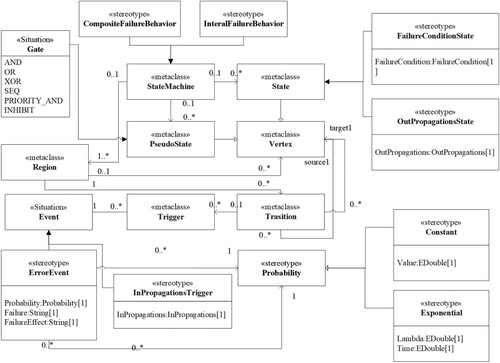
As shown in Figure , a SysML model is made up of several diagrams that can be specified into three categories. Block Definition diagrams(BDD), Internal Block diagrams(IBD), and Package diagrams (PKG) capture the architecture of the system, with Parametric diagrams (PAR) describing constraints on property values to support future analysis. Requirement diagrams(REQ) capture requirement, and requirement relationships. Activity diagrams (ACT), State Machine diagrams (STM), Sequence diagrams (SEQ) and Use Case diagrams (UC) describe the behaviour of the system. By extending a metaclass or generalising an existing stereotype, SysML allows users to extend and adjust existing metamodels for different domains. However, for safety-critical CPS systems, non-functional analysis is necessary to comply with relevant safety standards. Therefore, based on the full set of SysML, we select a relatively complete subset of SysML that meets the needs of safety-critical system modeling and can represent the system modelling process.
Figure 1. The metamodel of SysML.
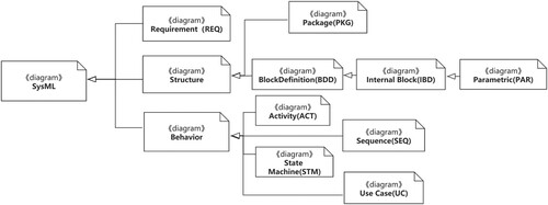
Based on the full set of SysML, a relatively complete subset of SysML that meets the needs of safety-critical system modelling and can represent the system modelling process is selected. BDD and IBD together describe the functional architecture of the system and are essential for the selection of subsets, STM focuses on the classification behaviour of system modules, the ACT is chosen to describe the behaviour of the system because it is readable and provides a large number of control elements that can describe the complex behaviour in the system. Moreover, the SysML safety extensions include three parts: the safety extension of requirements diagram, state machine diagram and activity diagram respectively. In addition, the assume/guarantee contracts are mainly extended on the block definition diagram and internal block diagram. Thus, the SysML subset considered in this paper includes REQ, BDD, IBD, ACT, STM and the Port and the Connector between blocks.
3.2. Extension with contracts
As mentioned above, when designing and verifying complex systems, the divide-and-conquer method is always adopted. In other words, the complex system is decomposed into several subsystems. Accordingly, the contract of the complex system is decomposed into contracts related to the subsystems. Then, the subsystems and their contracts can be further decomposed. With this hierarchical design, the complexity of the management system can be abstracted. In the perspective of verification, the traditional verification method is to directly transform and verify the entire flat model. However, such a method often faces the problem of state space explosion when verifying the model of complex systems, which makes it difficult to perform formal verification of complex models.
OCRA is a compositional and hypothesis-guarantee-based model checking tool, and can effectively solve the verification problem of complex systems. Due to the extensibility of SysML, we extend SysML with the OCRA contract specification language. The metamodel is shown in Figure .
Figure 2. Contract-based SysML extension model.
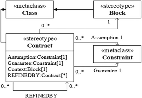
In OCRA, Contract and RefinedBy are the string attribute definitions, which describe the OCRA contract and refinement of contract (if it exists), respectively. As shown in Figure , the SysML block interface may contain a set of contracts. Each contract begins with the keyword “CONTRACT”, followed with the contract name and two constraint conditions indicating assumption and guarantee. The assumption is introduced through the keyword “assume”, which represents the attributes that the block environment must satisfy. The guarantee is introduced with the keyword “guarantee”, which represents the attributes that must be satisfied by the implementation of the block. In the block refinement, each contract existed in the block interface should be refined through certain sub-block contracts. The relationship is introduced through the keyword “REFINEDBY”, the former is the name of the refinement contract, the latter is the list of sub-block contracts.
3.3. Safety profile: SysML safety extension profile
Safety Profile extends SysML language with safety-related concepts to extend the system model. The main goal of this extension is to provide safety experts with structured and consistent modelling of the system to allow merging MDD and safety analysis processes. The safety analysis of the system is carried out in the system development process iteratively. With the refinement of the development, the safety analysis is continuously improved. In the preliminary stage of designing the system, if the risk sources and hazards in the system can be identified as early as possible, the impact of the hazard can be assessed to determine the system safety requirements, and the early safety analysis can be conducted, then it can reduce the cost of subsequent design modifications.
In the model-driven system development process, we use SysML and SafetyProfile to jointly construct the system model and the safety model. First, the requirements of the system need to be expressed in the concept development phase, i.e. the decomposition of the requirements, the assignment of functional requirements, and the failed states and safety requirements corresponding to the functional requirements are modelled in the requirements diagram. Second, after defining the structure of the system and the control flow of the normal behaviour in the system design phase, it is also necessary to define the error propagation model of the system. Then, the failure behaviour of the system is defined. To ensure the consistency of the safety information between the state machine diagram, the requirements diagram and the activity diagram, the failure behaviour model refers to the failure state defined in the requirements diagram and the error propagation defined in the activity diagram. Thus, a complete SysML model with safety information is constructed.
In the conceptual design of the system. We model functional requirements in the requirements diagram of the SysML model, assign functional requirements to system modules and identify and describe one or more failure states for each function. The domain expert defines the attributes of each failure state in the failure state list and formulates the corresponding safety requirements according to the severity of the failure state impact. It is important to note that a failure state may be caused by one or more failures and errors together, and such cases involving the system architecture will be considered in a subsequent phase. Further refinement of the safety model is carried out in parallel with the initial design of the system. In addition to the design of the system architecture and normal functional behaviour, it is also necessary to consider the establishment of the system error propagation model and failure behaviour model. A failure state may be caused by one or more failures and errors, and at least the following cases need to be considered: (1) Due to the hierarchical structure of the system, the logical combination of failure states of multiple sub-modules will lead to the failure of the module. (2) Due to the interaction between systems, one failure occurs before another failure can occur, i.e. there is a sequential requirement for the occurrence of failures. For example: for two systems S1 and S2, only after a failure occurs in S1 and is in the failure state, S2 may fail. (3) Failure itself does not directly affect the system, but these failures, when combined with some specific failure states, can pose a threat to system safety, or even cause a catastrophic failure state. (4) A function of different failure states may exist between the migration.
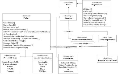
In SysML, requirements diagrams provide the ability to model text-based requirements and support the decomposition and assignment of system requirements but mainly express functional requirements. In order to express safety requirements in SysML, as shown in Figure , we introduced concepts such as Failure, FailureMode to determine the list of failure states corresponding to each function and to establish a tracking relationship between safety requirements and failure states.
Figure 3. The extended SysML safety profile for requirements diagram.
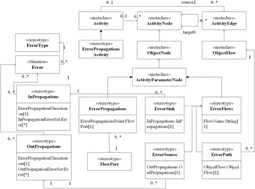
The structure view of the SysML model describes the hierarchical structure of the system. On top of the structure view, activity diagrams can describe the functional control flow between different modules as well as the input and output flow. However, the activity diagram cannot describe the error propagation between modules yet. We express the error propagation model based on <<ErrorPropagationsActivity>>, as shown in Figure , in which <<ErrorPropagations>> specifies the set of errors passed to or from the current module and the point of error propagation (flow port), while <<ErrorFlows>> expresses error propagation sources, paths and endpoints.
Figure 4. The extended SysML safety profile for activity diagram.
The StateMachine diagram of the SysML model tends to model the functional behaviour within a single functional module. We add a representation of the system failure behaviour, as shown in Figure . In the failure behaviour model, the module internal failure behaviour model is expressed by <<InternalFailureBehavior>>, which describes the state migration and egress propagation triggered by error events or incoming errors within the component, and the composite failure behaviour model is expressed by <<CompositeFailureBehavior>>, which describes the impact of the logical combination of submodule The impact of the logical combination of failure states on the module is expressed by the <<CompositeFailureBehavior>>.
Figure 5. The extended SysML safety profile for state machine diagram.
We use the metaclass “Situation” derived from the SysML standard safety extension (Biggs et al., Citation2019) to describe the properties of the Block, and uses the stereotype “Failure” to extend the “Situation” to indicate the possible unsafe state of the system functional component Block, as shown in Table . The failure-related information (e.g. the failure impact and the probability of occurrence) is presented by adding the Safety Profile. The attribute “FailureMode” describes the potential impact of the failure on the system, environment, and personnel. The related data type is the original type String of SysML. The attribute “FailureCondition” represents the severity of the impact caused by the failure. Its data type is the enumerated type “SeverityType”, and the related value is Catastrophic, Hazardous, Major, Minor, NoEffect. The attribute “Probability” represents the possibility of occurring the failure required by the system safety. Its data type is the enumerated type “ProbabilityType”, and the related values are Frequent, Probable, Remote, Extremely Remote, Extremely Improbable.
Table 1. Safety extension elements: failure.
To represent the internal failure of a single Block and the state transition of the Block after different failures in different states, the “StateMachine” is extended to the “ErrorStateMachine” to represent the state transition of the internal error of the Block. As shown in Table , “ErrorStateMachine” includes the original initial state of “StateMachine”, transition, and the stereotype “FailureState” extended from the metaclass State. “FailureState” represents a certain error state of en error that occurred in the Block, which is extended from the stereotype “ErrorEvent” and the stereotype “RecoverEvent” of the metaclass “Event”. The “ErrorEvent” represents the error event that occurs inside the Block, and the “RecoverState” represents the error recovery event that occurs within the Block. “ErrorEvent” and “RecoverEvent” are associated with the original element “Trigger” of the “StateMachine”. “Trigger” is the trigger of the state transition, which indicates the state changes when the error event associated with the trigger or the recovery event occurs.
Table 2. Safety extension elements: ErrorStateMachine.
A block can propagate failures to other blocks through ports and connections when its failure occurs, so it is necessary to describe the failure propagation between different blocks. As shown in Table , the metaclass “Trigger” is related to the “Port”, so the stereotype “ErrorInPropagation” is extended from the metaclass “Trigger” to represent the incoming fault that can be associated with the input port to indicate the specific input port. The same port can send multiple faults, such as value out of boundary fault, data delay and other faults. So the multi-value attribute “ErrorType” is added to represent various faults of the incoming port. The stereotype “ErrorType” extends Block in terms of inheritance, which can represent a self-defined error type. The Transition is associated with effect to present the impact behaviour when a state transition occurs, whose type is “Behavior”. Therefore, the extended “ErrorOutPropagation” of the metaclass “Behavior” is to represent the failure impact when the state transition occurs. Besides, the attribute “output” added to the “ErrorOutPropagation” represents the associated port where the failure occurred, whose type is “port”.
Table 3. Safety extension elements: ErrorPropagation and ErrorType.
4. Compositional verification and safety analysis of SysML models
This section provides the compositional verification and safety analysis approach of SysML models. It is achieved by the transformation from the SysML models with contracts into the formal specification of the OCRA tool and by the translating from SysML safety profile models to FTA.
4.1. SysML2OCRA: SysML model compositional verification with OCRA
The OCRA system specification generation for the SysML model is based on model transformation technology. Because SysML semantics is different from the OCRA system specification in terms of expressive power and scope, we only focus on a subset of the SysML model related to refinement, which specifically involves components, features, connections, and contract attribute sets. The global view of the mapping relationship between the SysML and OCRA Model elements is shown in Table . The detailed transformation rules are shown in Table , and Table . Especially, the model transformation language used in this paper is Xtend. Xtend can focus on the definition of model conversion rules without considering the pros and cons of the transformation algorithm and potential vulnerabilities in the design.
Table 4. Global view of the mapping relationship between SysML and OCRA.
Table 5. SysML2OCRA transformation rules (a).
Table 6. SysML2OCRA transformation rules (b).
4.2. Transformation from SysML safety profile to FTA
We present the automatic fault tree generation method based on Safety Profile, which can automatically generate a fault tree from the SysML model after the safety extension modelling, thereby eliminating the gap between the fault tree analysis tool and the safety analysis of the SysML model, as well as reduce the cost of safety analysis.
As shown in Section 3.3, Safety Profile can be summarised into three parts. The first one is the description extension of the safety information for hazard risk analysis, the second one is the extension of the block internal fault modelling, and the last is the extension of the block fault propagation modelling. The last two parts are mainly involved in the generation of FTA. The generation rules are given as follows.
Rule 1. The initial state of the “ErrorStateMachine” of the Block in the SysML model converts to the house event of the fault tree, which indicates a state that must occur. The error state “ErrorState” is converted to the intermediate event of the fault tree.
Rule 2. The error event “ErrorEvent” in the Block's ErrorStateMachine in the SysML model is converted to the bottom event of the fault tree.
Rule 3. “ErrorPropagation” of Block in SysML model is divided into “ErrorInPropagation” and “ErrorOutPropagation” according to the direction of the port. “ErrorInPropagation” is converted to the intermediate event of the fault tree, which means that it can be further decomposed into a combination of basic events. “OutErrorPropagation” is converted to the top event of the fault tree. Two situations that can cause the “ErrorOutPropagation”:
The first case: The “ErrorInPropagation” occurred in the initial state or the error state leads to the “ErrorOutPropagation”. The bottom event converted from the initial state and the intermediate event converted from “ErrorInPropagation” are connected through the logic && gate.
The second case: An internal error event occurred in the initial state or in an error state causes the “ErrorOutPropagation”. The bottom event represented with the initial state transition and the bottom event represented with the error event is connected by the logic && gate.
Rule 4. The transition of “ErrorStateMachine” in the SysML model is converted to a logic gate in the fault tree. If an error event occurred in the initial state or the error state is converted to the target error state, with the bottom event corresponding to the gatekeeper state or the bottom event corresponding to the intermediate event are connected with the error event through the logic && gate. If an error event occurred in the state or an incoming fault causes the transition to the same purpose error state, the bottom event corresponding to the error event is connected with the intermediate event corresponding to the incoming fault with the logic
gate. Then the state related to the logic && gate of the corresponding bottom event and intermediate event are connected through the logic && gate.
With the above generation rules, the basic correspondence between the extended elements in SafetyProfile and the elements of the fault tree is shown in Table .
Table 7. The mapping relationship between the safety profile elements and fault tree.
Moreover, the algorithm of automatic fault tree generation is presented in Algorithm 1, which mainly includes two parts: generating the internal fault tree of the block and generating the complete fault tree by combining the IBD diagram for the top events that need to be analysed. It first traverses the transition in the error state machine of each Block. If the source in the transition is “InitialState”, a corresponding bottom event will be added to the fault tree. If the source is “ErrorState”, a corresponding intermediate event will be added, which is the corresponding intermediate event added by the target of the transition. Then it processes the trigger associated with the transition. If the trigger is associated with “ErrorEvent”, the corresponding bottom event will be added. If the trigger is associated with “ErrorPropagation”, a corresponding intermediate event will be added, and the correspondence mapping relationship between the elements in the SysML model and the fault tree will be stored in a map. Finally, according to the input and output relationship of the ports in the IBD, the corresponding relationship between “InErrorPropagation” and “OutErrorPagation” can be found, and the intermediate event representing “InErrorPropagation” will be replaced with the top event representing the corresponding “OutErrorPagation” in the fault tree fragment, as well as a complete fault tree will be obtained by connecting the fault fragments of a single Block.
5. Prototype tool and evaluation
In this section, the prototype tools including SysML2OCRA and SafetyProfile2FTA are represented. Moreover, the effectiveness of the method proposed in this paper is illustrated through the industrial GNC case study.
5.1. Prototype tool
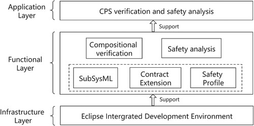
To evaluate the method proposed in this paper, we implement the prototype tool, on the Eclipse platform that integrates Papyrus, Eclipse Modeling Framework (EMF) and OCRA. We first establish the SysML model in Papyrus and use the SafetyProfile to extend the safety of the model. Then, we use EMF to respectively establish the meta-model (SysML.ecore) of SysML and the meta-model (SafetyProfile.ecore) of SafetyProfile, as well as generate the related code. We leverage the SysMLImporter module to read the .uml file and parse the SysML model, as well as generate the object for the SysML meta-model. The SysML2OCRA model can generate an OSS file for the given system and invoke the functions of OCRA to proceed the compositional verification. With the SafetyProfile2FTA model, a standard xml format fault tree model can be generated. We then can perform the safety analysis on the generated fault tree. The framework of the prototype tool is shown in Figure .
Figure 6. Overall architecture of the prototype tool.
5.2. SysML model for GNC system
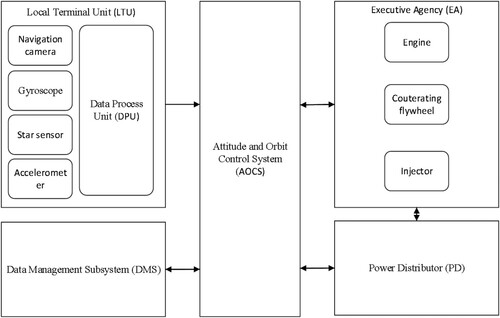
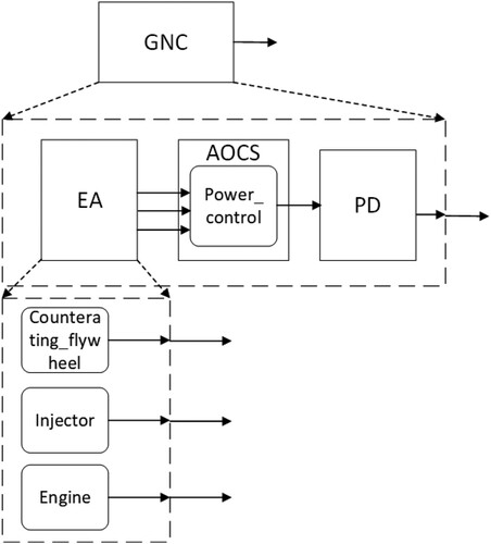
We now simply introduce the Guidance, Navigation and Control system (GNC) system that is the core guarantee system for spacecraft in orbit operation to control the normal operation of spacecraft in space (Negro & Phillips, Citation2010). As a typical reactive system, GNC system mainly includes three parts: input device, response device, and execution device. The input device is a navigation sensor, which is mainly composed of a navigation camera, a gyroscope, a star sensor, and an accelerometer, which are used to collect relevant data and information. The response device is mainly a control computer, also known as the Attitude and Orbit Control System (AOCS). The control computer receives the data information collected by the navigation sensor and processes it as required to generate control commands and send them to an executive device. The executive device is mainly the Executive Agency (EA), including engines, counteracting flywheels, injectors and other devices. EA starts after receiving the command, and completes the corresponding actions according to the command to adjust the attitude and orbit of the spacecraft. In addition, there is a device between the navigation sensor and the control computer, which is used to pre-process the data sent by the navigation sensor, called the Data Process Unit (DPU). The DPU and the navigation sensor form the Local Terminal Unit (LTU). In addition to the above-mentioned main device, there are two relatively small devices in GNC, namely the Data Management Subsystem (DMS) and the Power Distributor (PD). DMS mainly receives the information of EA and AOCS, and its function is to confirm the final information or simply process and store it. PD mainly exchanges information with the power management module in AOCS. Its function is to distribute power to various parts of the system so that they can work within the rated voltage range. The simplified architecture of the GNC model is shown in Figure .
Figure 7. The Simplified architecture of GNC system.
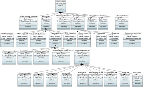
For the case of GNC system, our built SysML model contains 1 demand diagram, 1 BDD diagram, 73 IBD diagrams, 6 activity diagrams and state machine diagrams with 1,800 SysML system model elements (including 78 packages, 359 Classes, 343 Ports, and 71 Associations, etc.). Figure presents the BDD diagram of our built SysML model for the GNC system.
Figure 8. The BDD diagram of SysML model.
5.3. SysML models conversion to OCRA
With our built SysML model for the GNC system and the related requirements, we carry out 4 contracts that are written into the GNC model by our proposed SysML2OCRA tool to proceed the OCRA based contract compositional verification. Now, we detail the 4 contracts and the related verification results as well as analysis.
5.3.1. Contract-1 power distribution
Figure shows the structure diagram of the compositional verification for the power distribution. The contract “power distribution” involves three modules of EA, the power control and power distributor of AOCS. This contract can ensure that the total voltage does not exceed the maximum value when the reaction flywheel, nozzle, and engine are simultaneously executed. First of all, it is necessary to provide the three components with the rated voltage under normal working conditions. This is a non-functional requirement and a guarantee for the voltage output of the three components. Then, the AOCS power control module adds the voltages of the three actuators to represent the total rated voltage when working at the same time and produces it as the output. Finally, we will record and output the voltage value for the power distributor, and ensure that the total voltage does not exceed the maximum value at the overall system level. The specific content of the contract and its subcontracts are given as below, in which the component working voltage and total voltage are customised.
Figure 9. The structure diagram of the compositional verification for the power distribution.
In AOCS, the contract content is presented as follows:
In EA, the contract content is presented as below:
The specific contents of other contracts are provided in Table .
Table 8. Content of the power distribution.
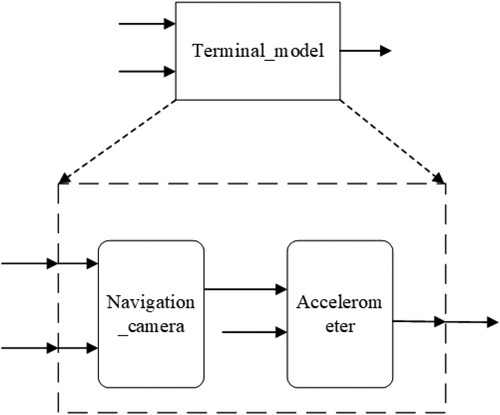
5.3.2. Contract-2 acceleration
Figure shows the structure diagram of combination verification for the contract acceleration. This contract involves the navigation camera and accelerometer components in the subsystem “Terminal_model” of the local terminal processing unit LTU. The contract assumes that the number of input port photos in “Terminal_model”, “Num_photo”, ranges from 1 to 1000, and the time of taking a single photo, “single_time”, is 0.02. This contract guarantees that the difference between the actual acceleration value and the maximum acceleration value of the “Terminal_model” output port does not exceed the maximum difference value, where the maximum acceleration and maximum difference are customised. In the sub-contract, the “Camera_time” of the output port of the navigation camera is guaranteed to be the product of the number of photos “Num_photo” multiplied by the single photo time “Single_time”, and the actual acceleration of the output port of the accelerometer “Actual_acceleration” is the quotient of the speed difference “Differ_speed” and 20.0. The specific content of the contract and its subcontracts are provided as below, where the maximum acceleration and maximum difference are self-defined.
Figure 10. The structure diagram of the compositional verification for the acceleration.
In Terminal_model, the contract content is presented as follows:

In the navigator camera, the contract content is provided as below:
In the acceleration, the contract content is given as follows:
5.3.3. Contract-3 cycle
Figure shows the structure diagram of the compositional verification for the contract cycle. The main purpose of this contract is to verify whether the execution sum cycle of all sub-component in the AOCS system is within the cycle of the entire system. To this end, we need to verify whether the sum time period of all parts is within the total system time period under the assumption of sequential execution (i.e. the sequence of attitude determination, orbit calculation, attitude control, and orbit control).
Figure 11. The structure diagram of the compositional verification for the cycle.
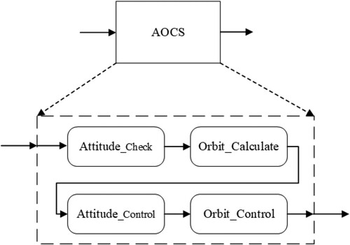
The contract assumes that the initial cycle “Cycle_time1” of the input port of the AOCS is 0, and guarantees that the “Cycletime_Output” of the output port does not exceed the self-defined maximum value. In the sub-contract, it guarantees that, for each component, the cycle time of the output port is results of the cycle time at the time of input plus its own cycle time, where the cycle time of each component is customised. The content of the contract and its sub-contracts are given in Table .
Table 9. Content of the contract cycle.
5.3.4. Contract-4 execution
Figure shows the structure diagram of the compositional verification for the contract execution. The contract involves three executive components in the executive agency. The contract mainly ensures that when the input port has data, the corresponding execution component is in the related working state.
Figure 12. The structure diagram of the compositional verification for the execution.
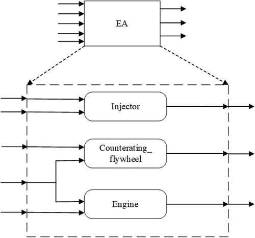
Specifically, when the values of cosine and angle are within the specified range, the injector should be in working condition. When the decreases of acceleration and speed are within the specified range, the counteracting flywheel should be in working condition. When the speed decrease or the speed increase is within the specified range, the engine should be in working condition. The content of the contract and its subcontracts are given below.
In EA, the contract content is as follows:
In counteracting flywheel, the contract content is as follows:
In the injector, the contract content is as follows:
In the engine, the contract content is as follows:
5.4. Compositional verification
Figure presents the results of compositional verification with aforementioned contracts. It shows that all contracts are verified correctly. It indicates that there is no problem with the refinement of the contract. Take the contract-1 power distribution as an example, at the GNC level, we guarantee that the total voltage does not exceed 1000, and the voltage of the three components in the actuator is 100. Their sum does not exceed 1000, so the contract combination verification is successful.
Figure 13. The compositional verification results for the GNC model.
If we change the limitation of the total voltage from 1000 to 100 at the GNC level (i.e. the guarantee is always (Power_Output<100.0)). the contract-1 power distribution verification in the GNC component is failed. The contract verification is still successful in EA. When the contract combination verification fails, we can find out the counterexample as shown in Figure that caused the failure.
Figure 14. Counter examples cause the failed compositional verification.
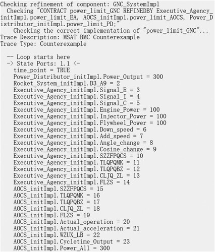
In the counterexample, the port values of the component that failed the compositional verification are presented, the voltage of the three components is 100 and the total voltage is 300. In EA, the guarantee content of the contract is always(Flywheel_Power = 100.0 and Inject_Power = 100.0 and Engine_Power = 100.0), and ensure that the voltage of the three execution components is 100. In the three execution components, the contract indeed guarantees that their voltages are 100, so the contract composition verification in EA is successful. After the data is transmitted to GNC through the power distributor, the value of Power_Output value is 300 that exceeds 100. It obviously does not satisfy the contract guarantee, and causes the compositional verification of contract 1 to fail.
5.5. Safety analysis
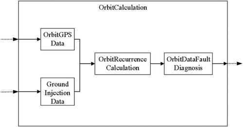
We take the orbit calculation system as an example to perform fault tree analysis. The main function of this subsystem is to perform autonomous orbit recursion and provide effective navigation data with a certain accuracy. Its architecture is shown in Figure , which contains four sub-modules: (1) GPS orbit data module: It obtains the initial value of the orbit from GPS and perform calculations. By default, GPS orbit information is enabled as the initial value recursion scheme. (2) Ground injection data module: It obtains and calculates the initial value of the orbit from the ground injection, which is used as the GPS backup. (3) Orbit recurrence calculation module: It uses the system clock and GPS data, or the on-satellite orbit calculation data to infer the number of orbital elements at other times. The initial value of the recursive orbit is the number of the most recent orbital number of GPS data (or on-board orbit calculation data). (4) Orbit data fault diagnosis module: It conducts the judgment with the number of orbits calculated from GPS or autonomous orbit extrapolation. If the orbit inclination calculated by the two methods exceeds the range of [95, 100
], the fault flag is set to 1. If the orbital inclination angles calculated by the two methods are within a reasonable range, it further judges whether the difference between i and Ω of the two methods is less than 0.05
and whether the absolute value of the difference between the orbital argument μ is less than 0.5Footnote1. If the two conditions are not satisfied, the fault flag is set to 2.
Figure 15. Orbit calculation system.
The fault tree constructed with the failure state “Calculated Orbital Elements Are Wrong” as the top-level event is shown in Figure . For simplification, the House Events true value is not shown in the figure. The basic events of the fault tree are labelled with numbers. When the orbit data fault diagnosis module fails, the subsystem cannot judge whether the number of orbits calculated by GPS or autonomous orbit extrapolation is reasonable or not, and it cannot set a fault flag. If both the initial value of the orbit calculated by the GPS orbit data module and the initial value of the orbit calculated by the ground injection data module is wrong at this time, or the orbit parameters calculated by the orbit recurrence calculation module are wrong, the number of orbital elements calculated by the Orbit calculation system is wrong.
Figure 16. The fault tree constructed with the failure state.
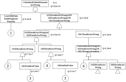
The basic events and minimum cutsets of the fault tree are presented in Tables and . According to the results of fault tree analysis, the minimum cut set with a probability of 1.344e−14 is the most dangerous. The basic events in this cut set are related to the GPS orbit data module and the orbit data fault diagnosis module, so it can consider increasing the redundancy of these two modules or adding protective measures to reduce the probability of basic events. Additionally, each minimum cut set includes the basic event “Fail Of Orbit Data Fault Diagnosis”, so the design of the orbit data fault diagnosis module will greatly affect the safety of the orbit calculation subsystem.
Table 10. The basic events of the fault tree in Figure .
Table 11. The minimum cutsets of the fault tree in Figure .
6. Related work
We represent the related work from two perspectives: compositional verification and safety extension of SysML and its safety analysis methods.
Model checking is a popular way to ensure the verification of SysML models. Ando et al. (Citation2013) propose to formalise SysML state machines with CSP. Calvino and Apvrille (Citation2021) propose a new model-checker that can be applied (almost) directly to the SysML model. Rahim et al. (Citation2015) propose a model-to-model transformation of SysML activity diagrams into modular Petri nets to support the formal verification of SysML specifications. Nevertheless, doing so, often faces the so-called state explosion problem. An approach to deal with the state-explosion problem is the use of compositional verification which leverages the structure of the system. In these techniques, the verification of a composite system is reduced to the verification of its parts. Compositional verification (de Oliveira et al., Citation2019) has been widely used in model-driven development in recent years. The model constraint language used in the UML OCL. Burgueño and Gogolla (Citation2017) verified and analysed by setting various functional or non-functional constraints to each model element, behaviour and interaction. The model basis of the HRC model as the SPEEDS framework in the EU SPEEDS project (Badouel et al., Citation2006), according to the HRC model, the theory and tool support including design, model construction, combined components and verification analysis are put forward. OCRA (Cimatti & Tonetta, Citation2016) the contract-based architecture model modelling combination verification and analysis, Yu et al. (Citation2015) propose the contract-based architecture model design and verification method, Zhan et al. (Citation2019) proposed to use the combination of AGREE and Simulink to verify complex systems. So, The Compositional verification based on contract can verify and analyse the architecture model of the complex system.
Safety analysis techniques and methods have the objective to assess the system safety during the design phase and ensure that the designed systems have satisfactory safety levels. Several techniques and methods exist and they can be classified according to different criteria. Since the SysML also supports less safety and reliability information in the capture system model, it is necessary to extend the safety to support the safety analysis in the SysML system definition layer. Some existing SysML safety extensions, such as Geoffrey Biggs et al. (Citation2016) propose a SysML safety extension to model some safety concepts in IEC61508, ISO12100 and ISO26262 with system design information, OMG (Biggs et al., Citation2019) propose a general safety extension Profile based on fault tree. Helle (Citation2012) proposed to extend the safety-related information into the system model by using the SysML extension mechanism to generate the minimum cut set and the reliability block diagram representing the cut set for each fault case. Garro and Tundis (Citation2012) propose a model-based system reliability analysis method RAMSAS, which combines SysML and Simulink tools to allow the reliability of the system to be verified by simulation. Mhenni et al. (Citation2016) propose a SysML oriented model-based system engineering MBSE, integrating FMEA and FTA safety analysis methods. These methods and tools fail to highlight fault propagation between components and also lack advantages in quantifying computational performance and reliability metrics. de Souza et al. (Citation2020) combined STPA and SysML modelling activities in order to allow simulation and formal verification of systems models. Munk and Nordmann (Citation2020) augmented of SysML models with component fault trees (CFTs) to support the fault tree analysis and the failure mode and effects analysis. Alshboul and Petriu (Citation2018) integrated safety analysis of SCSs within the Model Driven Engineering (MDE) system development process based on model transformation SysML automatically transformed in Fault Tree (FT) models and uses standard well-known techniques and open source tools for the modelling and analysis of SCSs. Baklouti et al. (Citation2019) recommendation based on the FMEA analysis in order to enhance the system design and make it comply with safety requirements. And integrate safety analysis in a model-based systems engineering approach to ensure consistency between system design and safety artefacts. Yakymets et al. (Citation2013) leveraged features of SysML modelling language, integration of formal approaches for automatic FT generation within an MBSE workflow. Sentilles et al. (Citation2009) integrate component fault trees into the UML, safety engineering approaches can be shifted to the level of model-driven development by integrating safety models into functional development models, which is consistent with us. but we use SysML is more suitable for modelling the CPS system. At the same time, we also considered the combination of contract and safety properties.
7. Conclusion
This paper proposes an integrated SysML modelling and verification approach to covering specification of nominal behaviour and safety, where compositional verification is used to verify the nominal behaviour of the SysML model and FTA is used to do the safety analysis based on the “Safety Profile” of SysML. At first, an extension of SysML is presented, in which the contract information (i.e. Assume and Guarantee) is extended for SysML block diagrams and a Safety Profile is proposed to describe safety-related concepts. Second, the transformation from SysML to the compositional verification tool OCRA is given. The automatic generation of OCRA system specifications can effectively maintain the nature of the original SysML model and reduce errors caused by manual writing. Third, the safety analysis is achieved by translating the Safety Profile model into FTA (Fault Tree Analysis). The goal is to provide safety experts with structured and consistent modelling of the system to allow merging MDD and safety analysis processes. In return, system architect's modelling is enriched and adjusted with the result of any safety analyses carried out with FTA. Thus, a thorough consistency is established between systems engineering and safety analysis artefacts. Finally, the prototype tools including SysML2OCRA and SafetyProfile2FTA are represented, and the effectiveness of the method proposed in this paper is verified through an industrial case study that is Guidance, Navigation and Control (GNC) system.
Disclosure statement
No potential conflict of interest was reported by the author(s).
Additional information
Funding
Notes
1 The i is the number of flat roots at the orbit angle, Ω is the number of flat roots at the ascending node equinox, and μ denotes the orbit amplitude angle.
References
- Ahamad, S. S., & Pathan, A. S. (2020). A formally verified authentication protocol in secure framework for mobile healthcare during COVID-19-like pandemic. Connection Science, 33(3), 532–554. https://doi.org/10.1080/09540091.2020.1854180
- Alshboul, B., & Petriu, D. C. (2018). Automatic derivation of fault tree models from SysML models for safety analysis. Journal of Software Engineering and Applications, 11(5), 204–222. https://doi.org/10.4236/jsea.2018.115013
- Ando, T., Yatsu, H., Kong, W., Hisazumi, K., & Fukuda, A. (2013). Formalization and model checking of SysML state machine diagrams by CSP#. In B. Murgante, S. Misra, M. Carlini, C. M. Torre, H.-Q. Nguyen, D. Taniar, B. O. Apduhan, O. Gervasi (Eds.), Computational science and its applications – ICCSA 2013 (pp. 114–127). Springer Berlin Heidelberg.
- Badouel, É., Benveniste, A., Caillaud, B., Delahaye, B., & Raclet, J. B. (2006). SPEEDS: speculative and exploratory design in systems engineering.
- Baklouti, A., Nguyen, N., Mhenni, F., Choley, J. Y., & Mlika, A. (2019). Improved safety analysis integration in a systems engineering approach. Applied Sciences, 9(6), 1246. https://doi.org/10.3390/app9061246
- Berumen-Flucker, B., Rodriguez, A., Cienega, L., Casanova, V., & Douphrate, D. I. (2019). Evaluation of safety management and leadership training using mobile technologies among logging supervisors. Journal of Agromedicine, 24(2), 1–8. https://doi.org/10.1080/1059924X.2019.1567420
- Biggs, G., Post, K., Armonas, A., Yakymets, N., Juknevicius, T., & Berres, A. (2019). OMG standard for integrating safety and reliability analysis into MBSE: concepts and applications. INCOSE International Symposium, 29(1), 159–173. https://doi.org/10.1002/iis2.v29.1
- Biggs, G., Sakamoto, T., & Kotoku, T. (2016). A profile and tool for modelling safety information with design information in SysML. Software & Systems Modeling, 15(1), 147–178. https://doi.org/10.1007/s10270-014-0400-x
- Brosgol, B. M. (2011). Do-178c: the next avionics safety standard. ACM SIGAda Ada Letters, 31(3), 5–6. https://doi.org/10.1145/2070336.2070341
- Burgueño, L., & Gogolla, M. (2017). Formally modeling, executing, and testing service-oriented systems with UML and OCL. In 15th international conference on service-oriented computing (Vol. 10601, pp. 113–122). Springer.
- Calvino, A., & Apvrille, L. (2021). Direct model-checking of SysML models. In Proceedings of the 9th international conference on model-driven engineering and software development – modelsward (pp. 216–223). SciTePress.
- Cimatti, A., Dorigatti, M., & Tonetta, S. (2013). OCRA: a tool for checking the refinement of temporal contracts. In 2013 28th IEEE/ACM international conference on automated software engineering (pp. 702–705). IEEE.
- Cimatti, A., & Tonetta, S. (2016, April). A temporal logics approach to contract-based design. 2016 Architecture-Centric Virtual Integration (ACVI) (pp. 1–3). IEEE.
- Clegg, K. D., Li, M., Stamp, D., Grigg, A., & McDermid, J. (2019). A sysml profile for fault trees – linking safety models to system design (Vol. 11698). Springer.
- de Oliveira, A. L., Braga, R. T. V., Masiero, P. C., Parker, D., Papadopoulos, Y., Habli, I., & Kelly, T. (2019). Variability management in safety-critical systems design and dependability analysis. Journal of Software Maintenance and Evolution, 31(8), e2202. https://doi.org/10.1002/smr.2202
- de Souza, F. G. R., de Melo Bezerra, J., Hirata, C. M., de Saqui-Sannes, P., & Apvrille, L. (2020). Combining STPA with SysML modeling. In IEEE international systems conference (pp. 1–8). IEEE.
- DO-178C, R. (2011). Software considerations in airborne systems and equipment certification. RTCA, Incorporated.
- Dubois, H., Lakhal, F., & Gérard, S. (2009, September). The papyrus tool as an eclipse UML2-modeling environment for requirements. 2009 Second International Workshop on Managing Requirements Knowledge (pp. 85–88). IEEE.
- Gacek, A., Katis, A., Whalen, M. W., Backes, J., & Cofer, D. D. (2015). Towards realizability checking of contracts using theories. In 7th international symposium NASA formal methods (Vol. 9058, pp. 173–187). Springer.
- Garavel, H., Lang, F., & Mateescu, R. (2015). Compositional verification of asynchronous concurrent systems using CADP. Acta Informatica, 52(4-5), 337–392. https://doi.org/10.1007/s00236-015-0226-1
- Garro, A., & Tundis, A. (2012). Enhancing the RAMSAS method for system reliability analysis – an exploitation in the automotive domain. In Proceedings of the 2nd international conference on simulation and modeling methodologies, technologies and applications (pp. 328–333). SciTePress.
- Group, O. M. (2007). Unified modeling language specification version 2.1.1.
- Hause, M. C., & Thom, F. (2007, October). An integrated safety strategy to model driven development with SysML. 2007 2nd Institution of Engineering and Technology International Conference on System Safety (pp. 124–129). IET.
- Helle, P. (2012). Automatic SysML-based safety analysis. In Proceedings of the 5th international workshop on model based architecting and construction of embedded systems, aces-mb@models (pp. 19–24). ACM.
- International, S. (1996). Guidelines and methods for conducting the safety assessment process on civil airborne systems and equipment. SAE International.
- Lee, W. S., Grosh, D. L., Tillman, F. A., & Lie, C. H. (2009). Fault tree analysis, methods, and applications: a review. IEEE Transactions on Reliability, R-34(3), 194–203. https://doi.org/10.1109/TR.1985.5222114
- Liu, J., Backes, J. D., Cofer, D. D., & Gacek, A. (2016). From design contracts to component requirements verification. In 8th international symposium on NASA formal methods (Vol. 9690, pp. 373–387). Springer.
- Mhenni, F., Choley, J., & Nguyen, N. (2016). An integrated design methodology for safety critical systems. In Annual IEEE systems conference (pp. 1–6). IEEE.
- Mhenni, F., Choley, J. Y., & Nguyen, N. (2015, September). SysML extensions for safety-critical mechatronic systems design. 2015 IEEE International Symposium on Systems Engineering (ISSE) (pp. 242–247). IEEE.
- Mo, H., Wagle, N. S., & Zuba, M. (2014). Cyber-physical systems. XRDS: Crossroads, The ACM Magazine for Students, 20(3), 8–9. https://doi.org/10.1145/2590778
- Munk, P., & Nordmann, A. (2020). Model-based safety assessment with SysML and component fault trees: application and lessons learned. Software and Systems Modeling, 19(4), 889–910. https://doi.org/10.1007/s10270-020-00782-w
- Negro, J., & Phillips, R. (2010). Guidance, navigation and control. Betascript Publishing.
- Rahim, M., Hammad, A., & Boukala-Ioualalen, M. (2015, July). Towards the formal verification of SysML specifications: Translation of activity diagrams into modular petri nets. 2015 3rd International Conference on Applied Computing and Information Technology/2nd International Conference on Computational Science and Intelligence (pp. 509–516). IEEE.
- Sabaghian, A., Balochian, S., & Yaghoobi, M. (2020). Synchronisation of 6D hyper-chaotic system with unknown parameters in the presence of disturbance and parametric uncertainty with unknown bounds. Connection Science, 32(4), 362–383. https://doi.org/10.1080/09540091.2020.1723491
- SC-205, R. F. (2011a). Formal methods supplement to do-178c and do-278a. RTCA, Incorporated.
- SC-205, R. F. (2011b). Model-based development and verification supplement to do-178c and do-278a. RTCA, Incorporated.
- Sentilles, S., Stepan, P., Carlson, J., & Crnkovic, I. (2009). Integration of extra-functional properties in component models. In 12th international symposium on component-based software engineering (Vol. 5582, pp. 173–190). Springer.
- Stewart, D., Whalen, M. W., Cofer, D. D., & Heimdahl, M. P. E. (2017). Architectural modeling and analysis for safety engineering. In 5th international symposium on model-based safety and assessment (Vol. 10437, pp. 97–111). Springer.
- SysML-Forum (2003). SysML FAQ. https://sysmlforum.com/sysml-faq/ [Accessed on Feb. 23, 2021].
- Tim King, D., & Bill Stclair, L. (2012). DO-178C takes safety-critical software development to the next level. Eetimes Com.
- Varghese, E. B., & Thampi, S. M. (2020). Towards the cognitive and psychological perspectives of crowd behaviour: a vision-based analysis. Connection Science, 33(2), 380–405. https://doi.org/10.1080/09540091.2020.1772723
- Weilkiens, T. (2007). Sysml-the systems modeling language. Elsevier Inc.
- Yakymets, N., Jaber, H., & Lanusse, A. (2013). Model-based system engineering for fault tree generation and analysis. In Proceedings of the 1st international conference on model-driven engineering and software development (pp. 210–214). SciTePress.
- Yang, Z., Hu, K., Ma, D., Bodeveix, J., Pi, L., & Talpin, J. (2014). From AADL to timed abstract state machines: a verified model transformation. Journal of Systems & Software, 93(2), 42–68. https://doi.org/10.1016/j.jss.2014.02.058
- Yu, H., Joshi, P., Talpin, J., Shukla, S. K., & Shiraishi, S. (2015). The challenge of interoperability: model-based integration for automotive control software. In Proceedings of the 52nd annual design automation conference (pp. 1–6). ACM.
- Yu, L., Duan, Y., & Li, K. C. (2020). A real-world service mashup platform based on data integration, information synthesis, and knowledge fusion. Connection Science, 33(3), 463–481. https://doi.org/10.1080/09540091.2020.1841110
- Zhan, H., Lin, Q., Wang, S., Talpin, J., Xu, X., & Zhan, N. (2019). Unified graphical co-modelling of cyber-physical systems using AADL and simulink/stateflow (Vol. 11885). Springer.
- Zhang, J., Cheng, Z., Cheng, X., & Chen, B. (2020). OAC-HAS: outsourced access control with hidden access structures in fog-enhanced IoT systems. Connection Science, 33(4), 1060–1076. https://doi.org/10.1080/09540091.2020.1841096
Appendix. Abbreviations
Table A1. The full names of abbreviations used in the paper.