
ABSTRACT
Smart Farming is a new and emerging domain representing the application of modern technologies into agriculture, leading to a revolution of this classic domain. CLUeFARM is a web platform in the domain of smart farming which main purpose is to help farmers to easily manage and supervise their farms from any device connected to the Internet, offering some useful services. Cloud technologies evolved a lot in recent years and based on this growth, microservices are more and more used. If for the server side, the scalability and reusability are solved in high proportion by microservices, on the client side of web applications, there was no independent solution until the recent emergence of web components. They can be seen as the microservices of the front-end. Microservices and web components are usually used isolated one of each other. This paper proposes and presents the functionality and implementation of a dependable workflow management service by using an end-to-end microservices approach.
1. Introduction
Nowadays, the Internet together with web and Cloud technologies are evolving at an increasing speed and many traditional desktop or self-hosted applications are ported to the Cloud to be easily accessed, scaled and managed. Moreover, the agriculture is one of the new fields where Cloud technologies are adopted, leading to the emergence of a new research field called “Smart Farming”.
Smart Farming is a new and emerging domain representing the application of modern technologies into agriculture, leading to a revolution of this classic domain. It uses the advantages offered by the Internet of Things, Big Data, Cloud Computing, actuators, sensors, geospatial localisation or drones to achieve a better productivity (Meola, Citation2016), fulfilling the needs of the actual society. The population is growing constantly and the amount of resources needed increases.
The novelty of our approach is given by the usage of microservices deployment model for smart farms systems compared with traditional monolithic approach usually used to deploy such systems. This can lead to better integration of smart farms functionalities and better performance for large-scale deployments.
The main idea behind the “Smart Farming” concept is to collect, process, store and analyse data from smart farms equipped with air, and soil wireless sensors (Kanjilal et al., Citation2014), to provide farmers with valuable information and insights regarding crop evolution (Walter et al., Citation2017). So, for instance, a support decision system can give information about performing different tasks such as configuring different parameters, starting/stopping the irrigation, turning on or off the lights. Furthermore, in the case of a distributed system that aims to manage a large number of farms, all collected data need to be processed in Cloud (Wolfert et al., Citation2017).
The main objective of this paper is to propose and describe in detail a new way of extending web applications, called ‘end-to-end microservices’. The applicability of this new architectural pattern is proved by integrating the new workflow management service into the CLUeFARM platform.
2. Related work
This work is based on two previous works. In Mocanu et al. (Citation2015), we propose a Cloud architecture for a smart farming system that aim to help farmers and, in Colezea et al. (Citation2018) and in Bojan et al. (Citation2015) we propose the CLUeFARM platform.
Although the CLUeFARM platform offers a multitude of services, there is always place for better, so the platform can be extended further in various areas. One of these areas relates to the need of the farmers to be advised and guided throughout the process of farming.
A workflow can be defined as a set of steps that comprise a work process, often a repeated process (Georgakopoulos et al., Citation1995). The steps can be a task, an event or an interaction that involves a person or a group of persons. A workflow can be sequential, when each step, except the first one, is dependent of the execution of the previous step or parallel, when two or more steps can execute concurrently. A workflow can also be seen as an abstraction of a real work, a process in a company or the life cycle of a plantation process.
A business process is also a set of related tasks that leads to a defined set of results (Fleischmann et al., Citation2012). The difference between a workflow and a business process is that a workflow is a more general term and it refers to a way to automate business processes. Michael Havey defines a workflow as a step-by-step algorithm to achieve a business objective (Havey, Citation2005).
The architecture consists of a series of components, the heart of the system being the runtime engine, which is responsible for executing the workflows (Yu et al., Citation2021). The humans can interact with the system through some graphic applications. They can create and update the workflows executed by the engine. The workflows should be stored in a database that can be accessed by the system administrator. The system must make available a method of administration and monitoring. It must be deployed on an application server and will be accessible through web services.
With the advent of the Cloud Computing, the business process modelling took a step further and has evolved to Business Process as a Service (BPaaS). Business Process as a Service sits on top of other three cloud services (IaaS, PaaS and SaaS) and is often described as a way of executing workflows (business processes) in the Cloud. Companies always tried to automate their processes. They did this by themselves or hire another company to automate the processes for them. Maybe a service-oriented approach is a better choice. This was the main idea of which the CloudSocket project starts (Lee et al., Citation2018).
Regarding smart farming concept there are different approaches in the literature. In Jindarat and Wuttidittachotti (Citation2015), the authors investigate the design of an smart farm system for chicken farming management, using embedded systems (e.g. Raspberry Pi and Arduino Uno) and smart phones. The system was used to monitor surrounding weather conditions including humidity, temperature, climate quality. The findings of the study showed that this type of systems can achieve cost reduction, asset saving and productive management. Although the study is very interesting, it is based on a traditional architecture that do not cope with challenges raised by a distributed resource management system.
In O'Grady and O'Hare (Citation2017) is presented a theoretical approach in designing and modelling farm-specific models. Further, it presents an overview of models within the farming enterprise and reviews the state of the art in smart technologies. One interesting conclusion of the study is that the monolithic nature of many models impose difficulties for individual farmers in applying such models in practice. So, a microservices approach could led to a better adoption of such models and systems in practice.
The authors of Moon et al. (Citation2018) start from the fact that the storage and processing of big data for smart farming applications become a huge challenge. They propose the technique of lossy compression which can unleash the power of compression to IoT systems because it can significantly reduce the data. Furthermore such a technique can be implemented mode efficiently in a microservice deployment approach due to the fact that it can be implemented easily as a microservice of the platform.
The paper (Muangprathub et al., Citation2019) proposes an IoT system and data analysis for smart farms. The presented system is based on three components: hardware to connect and obtain data of crops, web application to manipulate data and mobile application used to control the crop watering. This system is also deployed as a traditional system. A microservice deployment approach would be more suitable for large-scale deployment of a such system.
3. CLUeFARM platform extension
This work is based on existing CLUeFARM platform which is a Cloud-based platform that provides services to help farmers better manage smart farms. The services provided are divided into two directions, farm management services and social networking services. All these represent an integrated platform that can bring benefits to farmers. Figure shows the architecture of the platform. The platform consists of two applications that actively communicate with each other.
Figure 1. General architecture of the CLUeFARM platform (Musat et al., Citation2018).
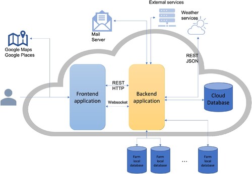
The backend application is, actually, a Java application, using the Spring Framework. We chose to use this framework because it is a huge platform with a large community that helps us to write web applications in a simple way, following the latest technologies as well. It is mainly used for the Java Enterprise Edition (Java EE) platform. We also use the Spring MVC framework that is based on the core framework. MVC (Model-View-Controller) is an architectural model in software engineering that has the role of delimiting the business logic from the user interface.
In addition, many modules are used within the platform which helps us to easily implement some of the features. The Spring Security Framework deals with platform security, access control and session management for users. We use Social Spring module to allow users to authenticate using third party platforms. For data access, we use Spring Data JPA that offers integrated CRUD (Create, Read, Update and Delete) methods. We can also create custom queries using an SQL-like language named JPQL (Java Persistence Query Language).
Regarding the data persistence, we chose to use a MySQL database as being the most popular relational database at the moment. Also, it is really easy to work with it. For adding default data in the database, we used Liquibase which manages and updates database scripts using MD5 technique to store the codification of the scripts to track any change inside update scripts.
The second application is represented by the frontend application. It is implemented using the AngularJS Framework which is a javascript framework that offers us a lot of features to easily develop a dynamic web application oriented to user interaction and user experience. We used Hyper Text Markup Language (HTML5) and Cascading Style Sheets (CSS3) to implement the markup and style section of the frontend application. We also use Bootstrap 3, a frontend framework which consist of html and css templates, with the purpose of helping us to create an interface that customers can easily understand. It also helps us to create a responsive application that can be naturally used on any device. We chose to implement the frontend application using the Single-Page Application (SPA) principle to replace loading new pages when navigating with rewriting them in the same page, all of this features being implemented using the javascript framework.
Representational State Transfer (REST) defines a set of constraints that can be used to create web services. These services provide interoperability between our frontend and backend applications. WebSocket is a communication protocol that provides full-duplex communication channel over a TCP connection. Only the backend application is responsible for communication with the database and it should send the data to the frontend application using these communication protocols. The platform also integrates with other external services. Some of these will be described below.
The frontend application uses two services, Google Maps and Google Places, to help farmers provide the geospatial coordinates of the greenhouses without having to know them. They can also search for localities on the map.
The backend application integrates with many external services such as e-mail service to send emails to users, weather service, responsible for sending weather data for a certain period in the greenhouse areas of the platform. At the same time, each user-registered farm must have saved login credentials to the local farm's database to retrieve the data to create some processing on it. In the current phase, the platform offers integration only with MongoDB databases.
4. Workflow management service
In the CLUeFARM platform, a workflow has the role of guiding a farmer during various activities that he performs in a farm. Regardless of farmer experience, he can use a workflow to assist his or just to remember him about the actions that need to be done on a certain date. This service will increase the farm productivity by guiding the farmers through the farming process or by helping them to fulfil administrative tasks.
Forwards, we will give a functional overview of the workflow management service, including two important user flows: creating a new workflow and subscribing a farm to a workflow. After that, we will explain the way of integrating this new service into the CLUeFARM platform using the end-to-end-microservice architectural pattern. Last, we will present some important technical design decisions that we have made and the technology stack used, along with the service specification and some implementation details.
4.1. End-to-end microservices
It is very difficult to maintain and extend a big web application, and such an application is also very hard to scale. One of the most important programming principles is the “Don't repeat yourself” (DRY) re-using the code principle (Hunt, Citation1900). This is a concept that help reduce the line of codes of a software and implicitly its complexity making it more manageable and less error prone. Having this principle in mind, a lot of libraries and frameworks were developed for all the programming languages commonly used (Apache Commons library suite, Spring Framework for Java;.NET framework for C#; Laravel Framework for PHP and so on). Their main purpose is to reduce code duplication and offer some “ready to use”, easy to plug in functionalities. A study made at Google it was proven that the most used code reuse possibility is the usage of the software libraries (89% of the engineers) followed by the software frameworks (53% of the engineers) (Bauer et al., Citation2014).
All the techniques mentioned above, together with design patterns and best practices that developers have to follow help only to reduce code duplication and solve repetitive tasks ( e.g. authentication, authorisation, parsing, data persistence) only from a technical point of view, having an increased level of abstraction. The business logic should be always built from zero. Considering the current situation, this is not enough anymore. The next level represents the possibility of reusing whole systems.
In general, modern web applications are divided into two main parts: a front-end application, responsible for the interface and the interaction with the user, and a back-end application responsible for the exposure of services. For both parts, there are ways of “plugging in” functionality by using components for the FE (any popular FE framework has a lot of UI components that can be used) and other services for the BE (a weather service for example).
Unfortunately, there is no easy way to have end to end reusable functionality. End-to-end functionalities are usually provided by whole applications or systems which comes with a lot of overhead (the biggest part of their offerings is not needed), they need to be deployed separately and are hard to configure and integrate. In this section, we will propose a solution for pluggable end-to-end functionalities based on the use of microservices and web components.
4.2. End-to-end microservice architecture
In the previous section, we have seen the advantages that a microservice architecture has over a monolithic one.
The reality is that in most of the cases only the backend is split into multiple microservices, the frontend application still being a monolith. There is only one big frontend application that communicate with the backend, usually through HTTP. There is a big progress comparing to one monolith application, or even worst, applications where frontend is server rendered.
In terms of code reuse, both frontend and backend applications can use frameworks or libraries, but if another frontend application would want to reuse the functionality offered by service one, the developing team will have to implement again all the communication logic. This approach could lead to code quality decreases and it also takes a lot of time.
In terms of code reuse, both frontend and backend applications can use frameworks or libraries, but if another frontend application would want to reuse the functionality offered by service one, the developing team will have to implement again all the communication logic. This approach could lead to code quality decrease and it also takes a lot of time.
Another approach for easily reusing the functionality offered by a backend microservice is to develop a team of the backend service and also build a frontend component that encapsulates the UI all the logic for communicating with the backend. The trade-off for this solution is that a component should be developed for each frontend framework, and this can be difficult because of the lack of knowledge and it also takes a lot of time.
4.3. Functional description
In CLUeFARM platform, a workflow represents a semi-automated flow of steps that will guide the farmers through different processes. By using the platform, the farmer can associate one or more workflows for many farms (many to many relationship). After the creation of a new workflow, the farmer will be notified through the notification service about the actions that he needs to, having a configurable grace period before task occurrence.
There are three possible types of flows that can be used in the platform:
Static workflows: This type of workflows is applicable to any farm and represents recursive administrative actions that occurs at fixed date, once a year for example. An example of such a task is the annual paying of taxes. These types of workflows can be defined only by an administrator of the platform and they can have one or multiple steps. Each step needs the confirmation of the farmer to be considered done.
Crop workflows: Those workflows refer to entire life cycles of crops. An example of a crop workflow is represented by the process of planting tomatoes. The seedlings need to be planted. After that they need to be irrigated, fertilised and finally harvested. This type of workflow can be defined by the administrator based on agriculture knowledge or by any user, but in this case the workflow needs to be approved by the administrator to be visible also to other users.
User defined(custom) workflows: This type of workflow has a similar structure with the crop workflows but do not refer strictly to planting actions, their actions are represented by any task that the user wants to do. So, those are fully configurable workflows, and they can be used without any restriction.
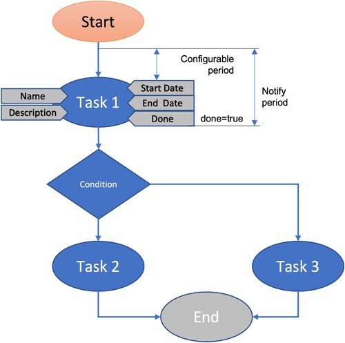
Figure presents a generic sequential workflow. It is a basic workflow composed of three tasks. One of the Task 2 or Task 3 is executed after Task 1 depending of the result of condition 1. Each node (task) is characterised by a couple of attributes like name, description, start date, end date and done. Those properties are specified at workflow creation time, excepting the done flag which is updated by the user when he completes a task. In the figure is also specified the period in which the user will be notified about a task (with a configurable period of time before the occurrence of the task).
Figure 2. Generic workflow.
There are two main actions that can be done in the platform related to workflow: the designing of a workflow and the subscription to a workflow.
4.3.1. Designing a workflow
In Figure , it is presented the steps that a user has to follow to design and register a new workflow within the platform. The user must be authenticated before accessing this service. After logging in, the service can be accessed by clicking on the “Workflows” menu item in the dashboard.
Figure 3. Designing a workflow.
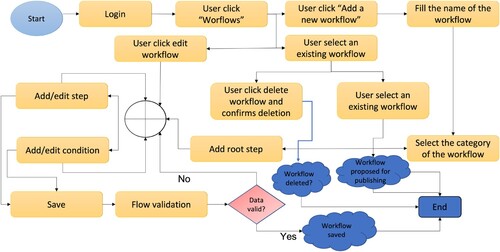
Inside the dashboard page, all the visible workflows for current user are listed and can be filtered by different criteria like name, category, keyword or only the owned workflows can be displayed. Starting from this page, multiple actions are possible:
Add a new workflow: By clicking on the “Add a new workflow” button, the workflow modelling page is opened. The mandatory information that should be filled in are the following: the workflow name, the category and the root step and the visibility. The category can be “Static”, “Crop” and “Custom”. The visibility can be “Public”, “Group” and “Private”. If a workflow is public, it can be viewed by any user; if the visibility is “Group”, then the workflow will only be visible to users from the groups to which the user belongs; a private workflow is visible only to the owner. Optionally, a list of keywords can be also added. Doing so, the workflow can be easily searched and found by other users. Adding a new step means specifying a name, a description, a start date, an end date and a parent, for non-root steps. A conditional step can be added by specifying a description. A condition can have two child steps, first will be executed if the condition is fulfilled and the second in the other situation. Any number of steps and conditions can be added. While adding the workflow steps, it can be easily reviewed because it is displayed in an intuitive way, like a graph. The workflow can be saved by clicking on the “Save” button. This action will trigger the syntactic validation of the workflow. If the workflow is valid, it will be saved and the user will be notified. Otherwise, user will receive a message containing the errors present in his design, errors they need to resolve to be able to save the workflow. After saving, the new workflow can be found on the workflow list.
Edit a workflow: A user can edit a workflow by selecting it from the list and click on the “Edit” button. The process of editing a workflow is the same as the process of adding it. A workflow cannot be edited if it is currently in use, but the user has the possibility to create a new version for it. In this way, the old version still can be used.
Delete a workflow: A workflow can be deleted after selecting it from the list, by clicking the “Delete” button. The user should confirm the deletion. A workflow can be deleted only if it is not used. Otherwise, an error message will be displayed.
Publish a workflow: For crop workflows, to be visible to other users, they should be published and approved by an admin. The user can request the approval by selecting a crop workflow and click on the “Publish” button. When this action occurs, the administrators are notified and after reviewing the workflow, they can approve or deny the publication.
4.3.2. Subscribing to a workflow
In Figure , the necessary actions for subscribing to a workflow are presented. Like any other service of the platform, the workflow service can be accessed only if the user is logged in. For viewing the list of workflows, the user should click on the “Workflow” item on the side menu of the dashboard (Figure ). After accessing the service page, the user can see a list of all available workflows, workflows that he can subscribe to. The user cannot see all the workflows in the platform, the list being filtered in advance. He can only see:
Owned workflows;
Crop workflows that are published and their visibility is even “Public” or “Group” and the current user is in the same group as the owner of the workflow;
All static workflows.
Figure 4. Designing a workflow.

Workflows can be searched by tags, by name and by type. After finding the desired workflow, in order to subscribe to it, the user has to select it, see all its details in a modal and then, click the “Subscribe” button. After that, the user has to select one or more of his farms for which he wants to subscribe, and then confirm this action.
The consequences of the subscription are that the user will be notified, using the existing “Notification Service”, about the deadlines and important events of each step for each farm. The resolution of each step should be manually updated by the farmer from the “Workflows” tab on the farm visualisation page. From the same tab, the farmer can unsubscribe from the workflow anytime he wants. This will cause the notifications to stop.
So, giving the possibility to the platform users (e.g. farmers) to add, define and use workflows related to farm activities represents a major step ahead regarding information sharing between farmers. Furthermore, by collecting information from different farms a guide of best practices can be shared between farmers.
4.4. Design decisions
4.4.1. Technology stack
The Workflow management service is developed separately from the CLUeFARM platform, following the microservice architectural pattern. We decided to do so because the platform is already big enough in terms of size and features, and by adding new features to it will make the code base harder to manage and extend. Another reason for choosing to build the service as a microservice are the advantages that this architecture has comparing to monolithic one.
The microservice will be developed using Java programming language with Spring Framework. This is a framework developed over Java EE which offers an infrastructure for easy development of Java applications. We choose to use this framework because with his aid the application can be developed faster in a modular way, using features such as “Dependency Injection” or “Aspect Oriented Programming”. Another big advantage that it offers is the removal of duplicated code normally written for doing common and repetitive tasks such as accessing the database. It is easy to integrate with other libraries or drivers.
A couple of Spring projects are used, like Spring BootFootnote1 for fast generation of the project having already done configurations. It also comes with a built-in web server (Tomcat), the installation of a separate one not being required for starting the application. Spring Security is used for handling the authentication and authorisation in a decoupled way, using aspects. Spring MVC (Model View Controller), as its name suggests, it offers an MVC architecture with already developed components for easy development of web applications. It is built around a servlet – DispatcherServlet – which is responsible for interception and routing of all the HTTP requests. Spring Data Neo4j offers advanced features for mapping between java objects (POJOs) and Neo4j database items (nodes, properties, relationships). It is based on the Neo4j-OGMFootnote2 library and it allows the auto-generation of Cypher Graph Query Language (declarative language for efficient querying and updating of graph properties) queries.
For build process automation and dependency management, we choose to use Gradle. This is a modern tool that took the advantages of his ancestors like Ant and Maven. Comparing to his ancestors who are based on XML, In Gradle scripts can be written in an own DSL language based on Groovy programming language which makes them easier to write and maintain (Conversations, Citation2018).
4.4.2. Authentication and authorisation
For authentication, we had to choose in the first place between using a stateful or a stateless authentication. In a stateful authentication, all the data is stored in a central place and for a complex architecture like a microservices architecture this can be a limitation. Also, if other data about the user is necessary, it should be retrieved from other source for every request, operation which impacts the performance (Peyrott, Citation2017). Usually, the stateful authentication is backed by a session id which is generated once the user is authenticated and this is most often a random string. This is one of the biggest advantages of this type of authentication because it offers opacity, but this can be also achieved by using stateless authentication.
Being in a microservices world, where data is split among the different databases of the services (the database of the CLUeFARM platform and the database of the Workflow Management Service in our particular case) the stateless authentication is the big winner. In our case, the new service should not even know the details of the platform user other than a unique identifier.
The implementation details of the authentication and the data flow of it will be presented in a following chapter. Although any kind of token cam be used for stateless authentication, our implementation is based on the JSON Web Token technology (JWT) which become a standard de facto for doing this. JWT is a compact, URL-safe means of representing claims to be transferred between two parties (Jones et al., Citation2015). The structure of a JWT can be seen in Figure . It is composed of three sections separated by a dot. The first section is the header and it is a JSON which have two claims, one for describing the algorithm used and other for specifying the type of JWT. The second section is the payload, which contains a JSON with the actual data. The third sections are the signature. All three sections are base64 encoded.
Figure 5. JWT structure.
By applying a digital signature on the JWT it becomes a JWS (JSON Web Signature). If the JWS is also encrypted, it becomes a so-called JWE (JSON Web Encryption) and by doing so, the token becomes opaque, as a normal session id.
4.4.3. Database
As we specified earlier, in general a microservice has his own database, as in the case of the Workflow Management Service. The first big decision that we had to take was to use an SQL or an NoSQL database. Into the SQL databases data is organised in tables with relations between them. Each column represents an attribute. SQL databases guarantee ACID transactions. It means that any transactions are Atomic (all the operations in transaction will complete or fail), Consistent (the database will be in a consistent state when the transactions begin and ends), Isolated (each transaction is executed like being the only transactions upon the database), Durable (if the transaction is executed successfully then it will not be reverted) (Li & Manoharan, Citation2013). For querying data, SQL language is used.
NoSQL (Not only SQL) databases refer to all data storing models which are different of the SQL model. This type of database was developed with some key principles in mind, like As we specified earlier, in general a microservice has his own database, as in the case of the Workflow Management Service. The first big decision that we had to take was to use an SQL or an NoSQL database.
Into the SQL databases, data is organised in tables with relations between them. Each column represents an attribute. SQL databases guarantee ACID transactions. It means that any transactions are Atomic (all the operations in transaction will complete or fail), Consistent (the database will be in a consistent state when the transactions begin and ends), Isolated (each transaction is executed like being the only transactions upon the database), Durable (if the transaction is executed successfully then it will not be reverted) (Li & Manoharan, Citation2013). For querying data, SQL language is used.
NoSQL (Not only SQL) databases refer to all data storing models which are different of the SQL model. This type of database was developed with some key principles in mind, like scalability availability, ease in processing huge amount of data and ease in partitioning data. They are characterised by BASE properties (Basically Available, Soft State, Eventually Consistent).
The data stored by the Workflow Management Service are workflows and information related to the subscriptions of farms to workflows. Considering the different types of workflows that are supported, the flexibility is one of the most important aspect that should be taken into consideration while choosing a database, this is why we decided to go for an NoSQL database. The application being a microservice, which will probably be scaled, the ease of scalability was another argument for not choosing an SQL database. As we will see in a following chapter, a workflow can be easily designed as a graph, so this type of NoSQL database is the most appropriate for our data. Other argument for choosing this type of NoSQL database is the fact that it is the most flexible model, and it can store very complicated structures. Because the chosen solution is a graph database, we will describe further in more detail this type of database.
We decided to use Neo4jFootnote3 graph database for our service. It is the most performant and popular graph database which offers graph data processing and storage, ACID transactions, CQL query language, rich APIs and drivers for C#, Java, JavaScript and Python programming languages. It also has a browser for visualise and query data.
4.5. Workflow management service architecture and data flow
The type of workflow implemented in this service is situated between a standard business process and a workflow, the letter referring to the automatisation of a business process. The workflows in cause cannot be automated because they involve the intervention of the user in every task. The user has to confirm that a task is done, otherwise the flow cannot be continued.
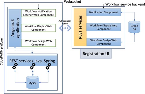
The “Workflow Service” is designed as a micro service, totally separated from the CLUeFARM platform. This can be seen also in Figure where the service architecture is presented along with the communication flow between the service in discussion and the platform. It is supposed to be a general solution for storing any kind of workflows, not only workflows needed by the CLUeFARM platform.
Figure 6. Workflow service architecture.
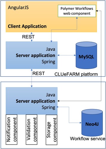
At this moment, the platform is composed of two main components, a client application, implemented using AngularJs framework and a server application, implemented in Java programming language, using Spring Framework. It uses a MySql database for storing data. The communication between the client and the server application is done using REST (representational state transfer) services, a common way of providing interoperability between applications over a network, often the used network being the internet. It uses the advantages (like stateless operations and the set of HTTP verbs) offered by the HTTP protocol to offer fast performance, reliability and extensibility.
The communication between the platform server application and the workflow service is done also through the REST services exposed by both of them. The platform uses all the endpoints exposed by the service for managing workflows lifecycle while the workflow service uses the notification service of the platform for notifying the users about the events occurrence. More details about the structure of the data transferred will be provided below.
The server application of the workflow service is implemented in Java using Spring Framework. It is a Java platform that provides support for building Java applications (Johnson et al., Citation2016). It is based on POJO (Plain Old Java Object) and dependency injection, these two contributing to the development of loosely coupled components. For building the rest services, Spring MVC framework is used, while as an OGM solution Spring Data is the choice. The workflows can be easily model as graphs, so the natural way of storing them is in a graph database. The chosen solution is Neo4J. It is an ACID compliant transactional graph database management.
The Workflow service is divided into three components:
Notification component: This component is responsible for event triggering. It constantly analyses the workflows and the subscriptions and when needed it triggers an event that will be sent to the notification service of the CLUeFARM platform. A notification must contain the farm id and a message;
Validation component: This component is responsible for syntactic validation of workflows, when they are created or edited;
Storage component: This is the component that communicates directly with Neo4J database and is responsible for CRUD (Create, Read, Update and Delete) operations on workflows.
The interface through which workflows can be added is not part of the CLUeFARM platform. It is delivered as an independent and reusable UI component. It is build using the PolymerFootnote4 library.
4.6. Workflow service integration into CLUeFARM platform
To prove the utility of the architecture described in Chapter 3 and better understand how it works we will present further the architecture and the integration process of the workflow management service into the CLUeFARM platform.
All these services are served by a monolith backend application which is already quite large. Adding additional functionalities to the same code base doesn 't seem to be a good idea in terms of performance and ease of management. This is why we decided to extend the platform with the help of microservices. The frontend application is also a monolith written in AngularFootnote5 Java Script framework. Considering all these aspects, the end-to-end architecture presented earlier fits perfectly.
In Figure , there can be found the architecture of the entire proposed system, the workflow service integrated into CLUeFARM platform. In the left side, there is the actual platform, composed of two big applications: a server application written in Java with Spring framework and a frontend application written in AngularJs. The backend application exposes a couple of REST endpoints and for all the services it uses a MySQL database for local data storage.
Figure 7. Workflow service integration into CLUeFARM platform.
On the right side of the diagram, there is the representation of the workflow microservice. It serves only one purpose: manage the lifecycle of the workflows. It can be written in any programming language as long it implements the required interface and is able to perform CRUD (Create Read Update Delete) operations on workflows. In this particular case, it is also implemented in Java using Spring Framework.
Workflows can be easily modelled as graphs, so to increase the performance and to store them in a natural way, a graph database will be used (Neo4j in this case – ACID compliant transactional graph database). The microservice is divided into three small components: notification component, validation component and storage component. They were described in the previous section.
In order for the end-to-end microservice to be completed, some UI part need to be provided. This is done through three different and independent Polymer web components. The three components are:
Workflow Notification Listener web component: This component is responsible for initialising a web socket communication and handling all the events received from the backend, independent of the application that uses it. The interaction between the application and component is done through the call-backs that the component offers. The application can choose to handle any of the events that it needs.
Workflow Display web component: This web component is able to display any workflow just by providing it with the workflow identifier of with the JSON representation of the workflow. In the first case, the component is also responsible for retrieving the workflow representation from the server.
Workflow Design web component: This is a more complex component used to design new workflows, delete or edit existing one. It offers an interface with drag and drop options for easily define workflows and events on each workflow step. It is also responsible for making the necessary calls to the server. The result of designing a workflow is a JSON representation of it.
Based on the needs of each application, only a part of the components can be used. For example, there can be cases where workflows only need to be displayed, so, in this case only the workflow display component will be used.
Regarding authorisation, we decided to use a token-based mechanism. To be allowed to use the workflow service, an application should be registered upfront. After registration, the user will be offered a token, which should be used as parameter for the web components.
Other configuration data as the URL of the back-end service should also be provided as parameters for the web components (if not, the defaults will be used).
4.7. Service specification
The microservice that we are describing has a Neo4J graph database used for storing data and it can be accessed through a couple of REST endpoints that he exposes.
All the endpoints, excepting the one that generates tokens (POST tokens) can be accessed only by authenticated users. The access token should be added to the “access_token” request header. All the endpoints are accessible only through HTTPS. The responses and HTTP response codes of the endpoints are standardised as follows:
200 OK is returned when the request was processed with success. When the request is a POST (create) or a PUT (update) the createdupdated resource is part of the response;
400 Bad Request is returned when the data provided by the client could not be interpreted by the server or do not follow the specification;
401 Unauthorised is returned when the “access_token” header cannot be found;
401 Unauthorised is returned when the “access_token” header cannot be found;
404 Not Found is returned when the requested resource is not found;
500 Internal Server Error is returned when something unexpected happens on the server side.
As we said before, the workflow management service allows the usage of three types of workflows. For simplicity, only static workflows will be treated further, along with the authorisation and authentication mechanism.
4.8. Implementation details
4.8.1. Authentication and authorisation
As we said earlier, almost all the endpoints of the Workflow Management Service require authentication. This is done using a signed JWT (JWS). It should be part of every request in a header called “access_token”. The next topic that will be discussed is the process of getting a JWT access token.
An access token that can be used for accessing the Workflow Management Service is always retrieved through an endpoint exposed by the service (“/api/tokens”). To get a valid token some information need to be posted to this endpoint in form of a JSON:
token – The unique token that the client application received after registering for using the service. This is a random string which identifies the client application and which is used to retrieve the custom configuration of that client application.
uid – The unique identifier of the user that is authenticated. The Workflow Management Service is not aware of user management so this value will be used and trusted as it is provided.
authorities – A list of authorities that the user has. This is also trusted by the Workflow Management Service, and based on this the authorisation will be done, according to the settings provided while registering the client application.
The interaction with the Workflow Management Service is done using a couple of web components. When they are used, they first search for a cookie with the name ‘wfms_access_token’. If the cookie is found, then it will be attached to all the requests. If not, then depending on the configuration provided it will request to the client application backend (CLUeFARM backend) a token (through a configurable endpoint). After that the JWT is retrieved and it will be sent back to the front-end (CLUeFARM front end in our case).
Figure 8. Authentication data flow.
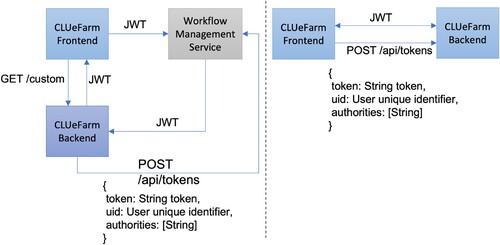
The second approach (right side of the Figure ) is less secure since it does not imply the client backend in the process of getting the JWT. The unique token should be provided as configuration parameter to the web components, together with the “uid” and user authorities. After that, the request for getting the JWT will be made by the web components themselves.
4.8.2. Workflow registration
To understand the Workflow Management Service and how can be integrated, we will explain further by example of adding a new workflow. For simplicity, we will use a static workflow. It has the role of reminding the farmer to pay taxes and it occurs yearly.
The interaction with the service is handled by a couple of web components that the client application has to use. For the action of adding a new workflow, the “workflow-design” web component is used. We assume that the authentication is already done and the “wfms_access_token” is set. The steps that need to be done are presented in Figure and explained further.
Figure 9. Register workflow.
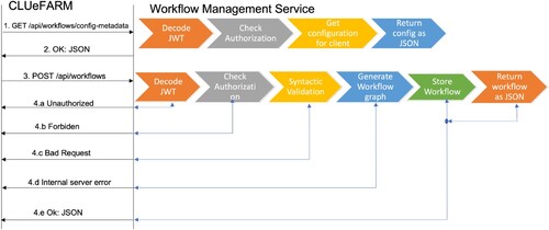
In the first step, the configuration is retrieved. The reason for retrieving the configuration is that it is different from client to client and it can be changed while registering the client application. For each request, the server is checking the signature of the token and decodes it (Decode JWT step). Having the information extracted from the token (client and user identifier and user authorities) authorisation is checked. For example, some users are not allowed to create workflows. Using the client identifier, the configuration is retrieved from the database and it is returned as a JSON (step 2). If the JWT is not found, then the 401 Unauthorised is returned (step 4a), while if the user is not authorised to do the action, then 403 Forbidden is returned (4.b). This is valid for all requests.
Having the configuration, the user designs the new workflow using the “design-workflow” web component and when he finishes it a POST request will be sent to the server, having in the body, a JSON representation of the designed workflow (step 3). After checking the authentication and authorisation, a syntactic validation is made. Each type of flow is backed by a JSON Schema, so a JSON Schema validator is used for this step (Syntactic validation step). If the validation fails, then 400 Bad Request is returned (step 4c). If the validation passes them the JSON of the workflow is parsed and the graph is generated. After that the graph is stored into the database. If some unexpected error occurs, then 500 Internal Server Error is returned (step 4d). If everything works ok, then the workflow is saved and it is returned to the client application (step 4e).
4.9. Workflow subscription
To subscribe to a workflow, a POST request should be made to ”/workflows/wfid/subscriptions” endpoint. The result of the subscription is that the workflow is copied, removing some irrelevant properties such as workflow type or occurrence and adding other properties like done or active meant to help manage the lifecycle of the workflow.
The new nodes are labelled as EXECUTABLE. The dates are not anymore relative; they are transformed to absolute dates, since after the execution of a workflow, it will be removed from the database.
5. Experimental results
In this section, the performance evaluation of the workflow management service will be presented. The tests were done on machine having the following specifications: processor – Intel Core i5, 3.1 GHz, 2 cores; memory – 8Gb, 2133 MHz; l2 cache – 256Mb/core; l3 cache – 4Mb; OS – macOS High Sierra.
Figure 10. Workflow service response times – 10 users.
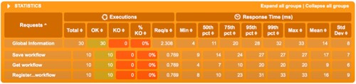
Figure 11. Workflow service response times – 100 users.
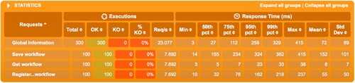
Figure 12. Workflow service response times – 1000 users.
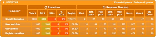
For testing the workflow management service, we choose three most important actions: creating a workflow, subscribing to a workflow and retrieving a workflow.
We run the test three times, increasing the number of concurrent users from 10 (Figure ) to 100 (Figure ) and 1000 (Figure ) in the end. The workflow that was used is the simple tax paying workflow.
As can be seen, the success rate is 100% for all three scenarios. For 10 simultaneous users, the response times are around 15 milliseconds for all three operations. For 100 and 1000 simultaneous users, the mean results are very similar even though the throughput was increased by 10 times: around 100 milliseconds for saving a workflow, 10 milliseconds for retrieving a workflow and 60 milliseconds for subscribing to a workflow. The maximum number of requests/s is of about 59.
6. Conclusion
The workflow service contributes to achieving the general objectives of the platform by assisting the farmers in applying the best farming practices. By using this service, a farmer can define his own workflows and follow the progress of his work in a timeline but he can also use the workflows defined by other farmers.
The service is implemented as an independent platform component, capable of storing any kind of workflows. It is implemented in Java programming language using Spring framework and has three main components: the notification component, the validation component and the storage component. The service also comes with a web component, implemented using Polymer library, a reusable and pluggable component that encapsulates all the UI needed for defining workflows.
Regarding the industrial relevance of our proposed solution, by using microservices and web components we designed dependable architecture for providing end-to-end microservices to farmers, having the highest level of code reusability.
The description and a general architecture of this new architectural pattern was presented. To prove its usability but also to improve the performance of the platform, the workflow management service was integrated into the CLUeFARM platform using this architecture.
The limitations of our approach are related to the basic knowledge that farmers need to have in order to build and use different workflows. Another limitation refers to the sharing of different workflows due to the fact that these are specific to each farm and some farmers do not want to share their insights. In this case the platform cannot be used full potential.
Acknowledgments
We would like to thank the reviewers for their time and expertise, constructive comments and valuable insight.
Disclosure statement
No potential competing interest was reported by the authors.
Additional information
Funding
Notes
References
- Bauer, V., Eckhardt, J., Hauptmann, B., & Klimek, M. (2014). An exploratory study on reuse at google. In Proceedings of the 1st international workshop on software engineering research and industrial practices (pp. 14–23). New York, NY: Association for Computing Machinery.
- Bojan, V. C., Raducu, I. G., Pop, F., Mocanu, M., & Cristea, V. (2015). Cloud-based service for time series analysis and visualisation in Farm Management System. In 2015 IEEE international conference on intelligent computer communication and processing (ICCP) (pp. 425–432). IEEE Explore.
- Colezea, M., Musat, G., Pop, F., Negru, C., Dumitrascu, A., & Mocanu, M. (2018). CLUeFARM: Integrated web-service platform for smart farms. Computers and Electronics in Agriculture, 154(7), 134–154. https://doi.org/10.1016/j.compag.2018.08.015
- Conversations, T. (2018). https://technologyconversations.com/2014/06/18/build-tools/.
- Fleischmann, A., Schmidt, W., Stary, C., Obermeier, S., & Börger, E. (2012). Subject-oriented business process management. Springer Nature.
- Georgakopoulos, D., Hornick, M., & Sheth, A. (1995). An overview of workflow management: From process modeling to workflow automation infrastructure. Distributed and Parallel Databases, 3(2), 119–153. https://doi.org/10.1007/BF01277643
- Havey, M. (2005). Essential business process modeling. O'Reilly Media, Inc.
- Hunt, A. (1900). The pragmatic programmer. Pearson Education India.
- Jindarat, S., & Wuttidittachotti, P. (2015). Smart farm monitoring using Raspberry Pi and Arduino. In 2015 international conference on computer, communications, and control technology (i4ct) (pp. 284–288). IEEE Explore.
- Johnson, R., Hoeller, J., & Donald, K. (2016). The spring framework-reference documentation, 2.0.5. urlhttp://docs.spring.io/spring/docs/current/spring-frameworkreference/htmlsing.
- Jones, M., Campbell, B., & Mortimore, C. (2015). JSON web token (JWT) profile for OAuth 2.0 client authentication and authorization Grants. https://tools.ietf.org/html/rfc7523.
- Kanjilal, D., Singh, D., Reddy, R., & Mathew, J. (2014). Smart farm: Extending automation to the farm level. International Journal of Scientific & Technology Research, 3(7), 109–113.
- Lee, S., Kim, H., Park, S., Kim, S., Choe, H., & Yoon, S. (2018). CloudSocket: Fine-grained power sensing system for datacenters. IEEE Access, 6, 49601–49610. https://doi.org/10.1109/ACCESS.2018.2868469
- Li, Y., & Manoharan, S. (2013). A performance comparison of SQL and NoSQL databases. In 2013 IEEE Pacific Rim conference on communications, computers and signal processing (PACRIM) (pp. 15–19). IEEE Explore.
- Meola, A. (2016). Why IoT, big data & smart farming are the future of agriculture. Business Insider, 20.
- Mocanu, M., Cristea, V., Negru, C., Pop, F., Ciobanu, V., & Dobre, C. (2015). Cloud-based architecture for farm management. In 2015 20th international conference on control systems and computer science (pp. 814–819). IEEE Explore.
- Moon, A., Kim, J., Zhang, J., & Son, S. W. (2018). Evaluating fidelity of lossy compression on spatiotemporal data from an IoT enabled smart farm. Computers and Electronics in Agriculture, 154(6), 304–313. https://doi.org/10.1016/j.compag.2018.08.045
- Muangprathub, J., Boonnam, N., Kajornkasirat, S., Lekbangpong, N., Wanichsombat, A., & Nillaor, P. (2019). IoT and agriculture data analysis for smart farm. Computers and Electronics in Agriculture, 156(9), 467–474. https://doi.org/10.1016/j.compag.2018.12.011
- Musat, G. A., Colezea, M., Pop, F., Negru, C., Mocanu, M., Esposito, C., & Castiglione, A. (2018). Advanced services for efficient management of smart farms. Journal of Parallel and Distributed Computing, 116(14), 3–17. https://doi.org/10.1016/j.jpdc.2017.10.017
- O'Grady, M. J., & O'Hare, G. M. (2017). Modelling the smart farm. Information Processing in Agriculture, 4(3), 179–187. https://doi.org/10.1016/j.inpa.2017.05.001
- Peyrott, S. (2017). https://auth0.com/blog/stateless-auth-for-stateful-minds/.
- Walter, A., Finger, R., Huber, R., & Buchmann, N. (2017). Opinion: Smart farming is key to developing sustainable agriculture. Proceedings of the National Academy of Sciences, 114(24), 6148–6150. https://doi.org/10.1073/pnas.1707462114
- Wolfert, S., Ge, L., Verdouw, C., & Bogaardt, M. J. (2017). Big data in smart farming – A review. Agricultural Systems, 153, 69–80. https://doi.org/10.1016/j.agsy.2017.01.023
- Yu, L., Duan, Y., & Li, K. C. (2021). A real-world service mashup platform based on data integration, information synthesis, and knowledge fusion. Connection Science, 33(3), 463–481. https://doi.org/10.1080/09540091.2020.1841110