
Abstract
Engineering changes (ECs) are raised throughout the product life cycle and their management can determine the commercial success of products. A well-established method to support engineering change management (ECM) is the change prediction method (CPM). The function–behaviour–structure (FBS) linkage method enhances CPM with an FBS scheme and allows more detailed modelling and analysis of ECs. The goal of this paper is to provide an industrial evaluation of the FBS Linkage method. For that purpose, we provide first an overview of the FBS Linkage method, before applying it to a diesel engine design and evaluating it by a group of 10 experienced engineers from the diesel engine manufacturer. Overall, the engineers favoured the FBS Linkage method and ranked it on average 3.7 out of 5.0 against a set of 25 different requirements for ECM methods. The evaluation underlines the benefits of the method in terms of a systematic way for capturing, explaining and transferring knowledge about the product and effects of ECs on it. Identified improvement areas include more guidelines on the scope of the method, reduction of the effort required to build FBS Linkage models, and an integration of the method into other applied systems.
1. Introduction
Modifications to the descriptions of technical systems are referred to as engineering changes (ECs) (Wright Citation1997). In today's customer-driven and dynamic markets, ECs cannot be avoided entirely; they are rather the rule than the exception (Clark and Fujimoto Citation1991). In fact, the existence of a successful engineering system is hardly imaginable without ECs (Fricke and Schulz Citation2005). ECs can be triggered by the customers, the management or company's internal departments, the suppliers or partners, and by market drivers such as technology and regulation. The purposes of ECs are manifold and can be generally grouped into variation or improvement, and correction initiatives.
Over the past two decades, academic interest in engineering change management (ECM) has risen (Hamraz, Caldwell, and Clarkson Citation2013a). Many in-depth company case studies have been conducted to understand the current practices and issues of ECM in order to derive the needs for future development (Jarratt et al. Citation2011). As a result, a variety of frameworks and tools aimed at aiding investigation, analysis, prediction of change propagation, and the management of ECs have been developed. However, ECs and their uncontrolled propagation still pose a challenge for industry. While many companies recognise ECs as being important for their businesses, very few have implemented dedicated change management tools with even fewer claiming that they can handle change issues successfully (Huang and Mak Citation1999; Maier and Langer Citation2011). Thus, further design research is required to support the practice of ECM.
In our past research at the Engineering Design Centre at the University of Cambridge, we have developed the change prediction method (CPM) in close collaboration with our industrial partners (Clarkson, Simons, and Eckert Citation2004). CPM models a product as a numerical network of its components and applies a stochastic algorithm to calculate the overall strength of component connections and thus the risk of change propagation between components. Successively, we have enhanced CPM by introducing a function–behaviour–structure (FBS) scheme to its product model. This method, termed FBS Linkage, models the product in greater detail and allows for more detailed analysis of ECs. While we have presented the development approach and some details of the FBS Linkage method in (Hamraz, Caldwell, and John Clarkson Citation2012; Hamraz et al. Citation2013b), an industrial evaluation still remains to be done. This is the focus of this paper at hand.
The remainder of the paper is structured as follows: Section 2 sets the background. Section 3 provides an overview of the FBS Linkage method. Section 4 presents its application to a diesel engine. Section 5 presents an evaluation of the FBS Linkage method. Finally, Section 6 summarises and concludes the paper.
2. Background
Dealing with ECs is not straightforward. Change initiated in one part of the system tends to have knock-on effects, triggering follow-up changes in other parts. This phenomenon known as change propagation (Terwiesch and Loch Citation1999; Fricke et al. Citation2000; Clarkson, Simons, and Eckert Citation2004) is very common to engineering products due to the high interconnectivity between their components. The first change in such a propagation chain is termed initiated change and the rest emergent changes (Eckert, Clarkson, and Zanker Citation2004). Change propagation can create a snowball effect, and in the worst case, an avalanche of change activity that may affect the whole system (Eckert, Clarkson, and Zanker Citation2004) and involve many partners collaborating in its development (Prasad Citation1997). The resulting impact can be very severe as it often entails both an increase in costs and a delay in schedules.
The Automotive Industry Action Group (AIAG Citation2012) reported for the North American automotive industry in total 350,000 ECs per year along with a processing cost (excluding materials and tools) of up to USD 50,000 per EC. Fricke et al. (Citation2000) concluded from a survey with German companies that 30% of daily work of engineers and managers is related to ECs. Maier and Langer (Citation2011) confirmed this for Danish companies based on a survey with more than 90 engineering firms from different industry sectors and sizes in Denmark. Loch and Terwiesch (Citation1999) investigated the impact of ECs on costs and schedules and found that ECs consume 33–50% of the engineering capacity at the firm they examined along with 20–50% of tool costs.
To support ECM, many methods and tools were developed. Based on a comprehensive systematic literature survey and categorisation, Hamraz et al. (Citation2013b) identified 54 ECM methods. These methods support knowledge representation in product design and have a fundamental goal in common: they capture tacit knowledge that is held as experience in the heads of designers and make it formal and available within the whole organisation (Chandrasegaran et al. Citation2013). In their core, most methods include a product model and a technique to predict and analyse the impact of change propagation. Traditional methods predominantly focus on a single product layer such as the structural or behavioural layer; they include C-FAR (Cohen, Navathe, and Fulton Citation2000), RedesignIT (Ollinger and Stahovich Citation2004), and CPM (Clarkson, Simons, and Eckert Citation2004). CPM models a product as a network of its components, quantifies the direct links between the components, and uses this numeric network to calculate the risk of change propagation between components, considering direct and several steps of indirect propagation. Some methods aim specifically at change propagation between different organisations in alliances; they include the distributed ECM (Chen, Shir, and Shen Citation2002), the parameter-based method (Rouibah and Caskey Citation2003), and ADVICE (Kocar and Akgunduz Citation2010). More recent developments have a stronger focus on multiple information layers and try to consider not only intra-layer but also cross-layer paths that change can take for propagation; they include the pattern-based method (Chen, Macwan, and Li Citation2007), the method using a unified feature modeling scheme (Ma, Chen, and Thimm Citation2008), the multi-domain change propagation network (Pasqual and De Weck Citation2012), the Contact and Channel Model (Albers et al. Citation2011), the method using the Axiomatic Design Matrix (Janthong Citation2011), the interface representation model (Rahmani and Thomson Citation2011), and the multi-domain system network (Van Beek and Tomiyama Citation2012).
The FBS Linkage method falls also in this last category, because it uses information from the three layers of structures, behaviours, and functions. Thereby, structure refers to what the product consists of, behaviour to how its constituent parts act or react in their environment, and function to what these behaviours are used for (Gero Citation1990). The method uses concepts from functional reasoning. Typical of functional reasoning approaches in engineering design are representational mechanisms of functional concepts together with description mechanisms of state or structure and behaviour and explanation mechanisms for functions (Far and Elamy Citation2005). Seminal examples include the FBS schemes from Gero and his colleagues (see, e.g. Gero Citation1990), Goel and his colleagues (see, e.g. Goel, Rugaber, and Vattam Citation2009), and Tomiyama, Umeda, and their colleagues (Umeda et al. Citation1990). All three schemes represent the functions, behaviours, and structure of products explicitly and model causal relations between them while avoiding hidden or implicit dependencies. They allow capturing ECs which (initially) might affect any product attribute. However, all three ontologies focus on a very granulated level of detail and have been applied primarily to products of low to medium complexity so far. Reported application examples include a gyroscope composed of 7 components (Goel, Rugaber, and Vattam Citation2009), a nitric-acid cooler composed of 6 components (Goel and Stroulia Citation1996), a copier composed of 6 components (Umeda et al. Citation1996), a vacuum cleaner composed of 11 components (Umeda et al. Citation2005), and a buzzer composed of 4 components (Qian and Gero Citation1996). More complex examples include a shifting system of a student racing car composed of 18 components, which in a reduced form leads already to a FBS network composed of over 100 unique elements (Van Beek, Erden, and Tomiyama Citation2010). While these three seminal ontologies are very useful for reasoning purposes which go beyond the analysis of change propagation, they seem to be too rigorous for complex products where change propagation is more relevant. Furthermore, the ontologies define the attributes of all three layers and elaborate their inter-layer links, but they do not specify the links between attributes of the same layer (i.e. intra-layer links). Thus, they do not provide all information needed to build a complete product network which could be used for change propagation modelling. Finally, the effort of developing the ontologies is relatively high as all attributes have to be individually identified, described, and interlinked. Though the number of structural attributes is limited, there is a high number of behavioural attributes. This is especially true for the state-transition-based ontologies from Goel and colleagues and Tomiyama and colleagues which represent behaviours as a sequence of state transitions.
In order to allow the application of FBS thinking to ECM, a modified ontology was developed for FBS Linkage (Hamraz, Caldwell, and John Clarkson Citation2012). This ontology adapts Gero's FBS model for the behavioural and structural layers, and combines it with the reconciled functional basis reported by Hirtz et al. (Citation2002) for the functional layer. The latter was included because it supports the systematic development of functional block diagrams and reduces ambiguity by providing a comprehensive dictionary of functions and flows. This dictionary helps to reconcile different notions of function, which otherwise can lead to inconsistencies while modelling the function structure of an existing design (Eckert et al. Citation2011). Helms, Shea, and Hoisl (Citation2009) and Helms and Shea (Citation2012) followed a similar approach and incorporated the functional basis into the FBS scheme from Tomiyama, Umeda, and colleagues (Umeda et al. Citation1990).
The requirement-based approach undertaken to develop the FBS Linkage method was presented in (Hamraz et al. Citation2013b). An earlier status of the method including details on the ontology and underlying assumptions and an initial application to a simplified model of a diesel engine design was presented in (Hamraz, Caldwell, and John Clarkson Citation2012). The next section will provide an overview of the FBS Linkage method.
3. The FBS Linkage method
The FBS Linkage method combines the concept of CPM with an FBS scheme and follows the four stages as depicted in .
Figure 1. Concept of the FBS Linkage method (colour online).
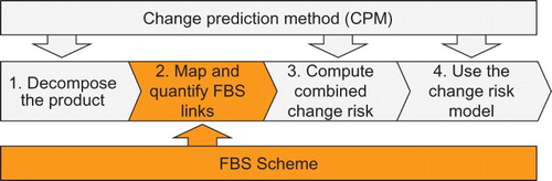
3.1. Decompose the product
Depending on the desired level of detail, a product can be decomposed into its systems, assemblies, components, parts, or a mix of those, if, for instance, some systems need to be modelled in greater depth than others. The higher the degree of decomposition, the more information about the product can be stored and the more precisely change propagation can be modelled.
In practice, the level of detail should be chosen to suit the anticipated application of the model. For example, if the purpose of the model is to support management decisions related to price estimations and overall project planning of a requested design modification, a less detailed model would be sufficient. Such decisions are relevant, for instance, when customers ask for a modified version of a product model. To compete in the bidding process, quick high-level assessments of the change effort and required delivery time are needed. However, if the model should be used by the designers to analyse ECs and support their day-to-day decisions, a more detailed model is required. For instance, a component designer might want to know which specific attributes of his component are affected by a change.
3.2. Map and quantify FBS links
An FBS scheme can be developed for the design to be analysed following the five steps depicted in .
Figure 2. Step-by-step development of an FBS Linkage scheme (colour online).
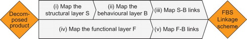
For a given decomposed product, (i) structural and (ii) behavioural attributes can be defined and their elements linked to each other within each layer. For the structural layer, a number of ideally independent attributes can be considered, such as Material (i.e. material type, specific material properties, etc.), Geometry (i.e. diameters, form, shape, etc.), Surface (i.e. surface finish, surface properties, etc.), Colour (i.e. colour saturation, intensity, etc.), and Controller (i.e. transistors, chips, microprocessors, etc.). For the behavioural layer, different types of preferably independent behaviours should be identified, such as Mechanical (i.e. all behaviours to do with weight, moments of inertia, etc.), Thermal (i.e. all temperature- and heat-related behaviours), and Electrical (i.e. all behaviours to do with current, voltage, etc.).
Then, (iii) the structural elements that determine the component behaviours must be linked to each other. Because the relation between structure and behaviour is determined by physical laws that apply to all components, the mapping between structural and behavioural attributes can be developed independently from the components. However, for some components, certain links might be irrelevant for EC propagation and can be omitted, for example, the influence of the structural attribute Colour on Thermal behaviour is often insignificant compared to the influence of Material on Thermal behaviour.
In parallel, (iv) the functional layer can be mapped as a functional block diagram composed of functions interlinked by flows of energy, material, and signal based on the reconciled functional basis (Hirtz et al. Citation2002). The functional layer considers the whole product and has a separate hierarchical structure, independently from the level of decomposition of the product into systems, components, or parts.
Finally, (v) to obtain the function–behaviour links, the functions can be assigned to components that realise them and then specified to responsible component behaviours.
The result is a product linkage model – the FBS Linkage scheme. This scheme can be represented as a network or as a corresponding multidomain matrix (MDM). As illustrated in , the FBS Linkage network is composed of structural, behavioural, and functional elements which are linked to each other within and between the layers. This three-layered network is a more detailed product model than the flat CPM network. By explicitly considering functional, behavioural, and structural attributes of the product, the FBS Linkage method transforms a great deal of tacit knowledge into available formal knowledge. Consequently, the method enables more detailed analysis of changes because it allows investigation of changes that affect any product attribute or link. Furthermore, it models the product in the context of its functions and working mechanisms and thus enables reasoning about change propagation and supports change containment and solution development.
Figure 3. FBS Linkage network and the corresponding ontology assumptions.
Next, the direct FBS links can be quantified by likelihood and impact of change propagation. This step can be either undertaken simultaneously while mapping the different network layers during the steps (i)–(v) or at the end when the FBS Linkage scheme is complete. Direct likelihood considers the relative frequency of change propagation between two components, and direct impact considers the relative severity of propagated changes. The change likelihood from one element E1 to another E2 is defined as the proportion of changes to E1 which propagate to cause change in E2. For instance, if every second change of E1 causes a change in E2, the likelihood is 0.5. The change impact from E1 to E2, on the other hand, considers the average proportion of the original design effort that would be required to modify E2 to accommodate a change propagated from E1. For instance, if a propagated change from E1 to E2 affects one-fifth of the design of E2, the impact is 0.2. Both values can be elicited from experts based on their prior experience and knowledge of the product. For these estimations, the average of many possible changes (i.e. average change magnitude) and a wide range of change mechanisms and propagation paths are considered. Thus, the obtained combined risk values in the next step represent a general risk profile for the whole design, applicable to a wide range of changes. However, if a risk profile for a specific change of a given element with a given magnitude is required, the direct change likelihood and impact values between that element and its direct neighbours could be determined more accurately and replace the generic values.
While the original CPM approach only captures the links between components, and subsumes all types of interactions (i.e. structural, behavioural, and functional) into a single number, the FBS links are more detailed and specific. The existence of a link between any two elements may be explained based on reasoning in the context of the product's functions and working mechanisms. In principle, at least some of the impact and likelihood values might be possible to calculate directly. For instance, the dependency between Material and Thermal behaviour might be described using mathematical equations which relate their parameters to each other. Where such calculations are possible and feasible with a reasonable amount of effort, objective values can replace the estimations, and this will improve the model's fidelity. An algorithm to achieve this under some circumstances is discussed in (Hamraz et al. Citation2013c). However, maintaining the probabilistic character of CPM is generally appropriate. The probabilistic approach reduces the complexity and effort of model building, because estimated linkage values are much easier to obtain than the results of deterministic calculations.
In general, each link between two elements could be quantified individually and separately for each direction. However, to minimise this tedious task of quantifying the available links one by one, three shortcuts can be taken: (1) the values of many links can be assumed as symmetric; (2) the links between the structural and behavioural elements which are mostly independent from the components can be quantified collectively first and then changed for exceptions; and (3) some other links can be quantified by standard values if they have not been specified yet, for example, 0.5 for likelihood and 0.3 for impact. The remaining links can be quantified using three different values, for example, 0.3 for low, 0.5 for medium, and 0.8 for high. To estimate these values, the relations between directly linked attributes can be investigated for generic changes. The network representation is more useful for this step.
3.3. Compute combined change risk
Combined risk of change propagation is the sum of direct and indirect risk, where direct risk between two components is defined by the product of direct likelihood and direct impact between them, and indirect risk considers change spreading via intermediate components. The indirect risk from an initiator to a target is defined by the sum of all risks imposed from penultimate components (other than the initiator) to the target. The imposed risk of a penultimate component to the target is the product of the combined likelihood from the initiator to the penultimate component and the direct risk from the penultimate component to the target. The combined risk of change propagation is calculated using the Forward CPM algorithm, which considers how change can propagate between any pair of elements through multiple direct and indirect paths. In overview, the algorithm operates by applying intersection and union operators along the change propagation paths to calculate path likelihoods and impacts while excluding self-dependencies and cyclic paths. Full details of the equations are provided in (Simons Citation2000; Clarkson, Simons, and Eckert Citation2004; Keller Citation2007). The algorithm is implemented in the freely available software program Cambridge Advanced Modeller (CAM) (Wynn et al. Citation2010).
3.4. Use the model
The FBS Linkage scheme shows how the product's structure is organised to exhibit actual behaviours which realise its functions. The outcome can be applied for both qualitative and quantitative analysis of the design and change propagation. The qualitative FBS network can be applied to reason about changes for the purpose of solution development and change containment. For instance, when a function has to be changed, tracing links in the FBS network allow identification of the different behaviours which realise this function and, in turn, the structural elements which exhibit those behaviours. Studying the network thus helps to identify the elements that could be involved in a change. At the same time, the FBS network can be used to investigate which elements should be manipulated to accommodate the functional change most effectively. The quantitative results could be applied to analyse change propagation. The focus of the model is the product domain. Other domains such as design process, organisation, manufacturing and supply chain could be incorporated into the model for a more comprehensive management of ECs.
4. Application to a diesel engine design
The engine modelled here is Perkins' VistaD diesel engine as partly discussed in (Jarratt, Eckert, and Clarkson Citation2004; Keller, Eckert, and Clarkson Citation2009; Hamraz, Caldwell, and John Clarkson Citation2012). The definition of different types of links in the existing CPM model helped to map and quantify the structural and behavioural layers of the FBS Linkage model. The functional layer and the inter-layer links were developed additionally with support from Tom W. Ridgman, a diesel engine expert from the Institute for Manufacturing at the University of Cambridge. Mr Ridgman has worked in the automotive industry for 20 years, in a variety of roles in new product development, manufacturing strategy and operations, including more than 5 years in the diesel engine product development of Perkins.
The FBS Linkage model for the diesel engine was built following the steps described in Section 3. For the quantification of the links, existing CPM models of the engine were used in combination with further assumptions as described below for the additional links that were not part of those CPM models. As the focus of this study was to evaluate rather the whole method than the fidelity of diesel engine model, in this study, standard values were assumed for those additional links. These values seem reasonable for an initial model of the engine but may be further refined to improve the confidence of the output.
4.1. Decompose the diesel engine
The diesel engine was decomposed into 42 components ().
Table 1. Component decomposition of the diesel engine.
4.2. Map and quantify FBS links
(2i) Map the structural layer S: The four structural attributes Geometry (Ge), Material (Ma), Surface (Su), and Controller (Ct) were used to define (42·4=) 168 structural elements. The structural links between these elements were drawn and quantified from existing CPM models of the engine.
(2ii) Map the behavioural layer B: Similarly to the structural elements, (42·3=) 126 behavioural elements were defined using the three behavioural attributes: Mechanical (Me), Electrical (El), and Thermal (Th). The behavioural links between these elements were drawn and quantified from existing CPM models of the engine.
(2iii) Map the structure-behaviour (S-B) links: The links between the structural and behavioural elements were identified collectively and symmetrically for all corresponding elements using the attribute relations depicted in . If the attribute link was not relevant on the element level, it was removed subsequently. These links were quantified using standard values of 0.5 for change likelihood and 0.1 for change impact. The likelihood value of 0.5 assumes that only half of all changes are critical enough to propagate and the impact value of 0.1 assumes that the re-design effort required to accommodate propagated changes amounts 10% of the initial design effort. These assumptions seem reasonable as initial values for a collective quantification of all existing links and may be refined for individual links as the model evolves.
(2iv) Map the functional layer F: The functional model of the diesel engine was developed by applying the reconciled functional basis from Hirtz et al. (Citation2002) to detail the four diesel strokes. Forty subfunctions were identified and interlinked by flows of material, energy, and signal ().
Fuel, air, oil, exhaust gases, and piston were used as material flows. The flows of energy were differentiated into thermal, electrical, rotational, translational, pneumatic, hydraulic, acoustic, and vibrational. Signal includes the interaction with the engine user in order to start the engine and control its speed. Although the functional block diagram in is directed, it was considered to be undirected for change propagation because changes can propagate forwards and backwards along the flows. These links were quantified using one of three standard values for change likelihood (i.e. 0.3 for low, 0.5 for medium, and 0.8 for high likelihood) and 0.1 for all change impact values.
Figure 4. Defining the links between the structural and behavioural attributes of the diesel engine (colour online).
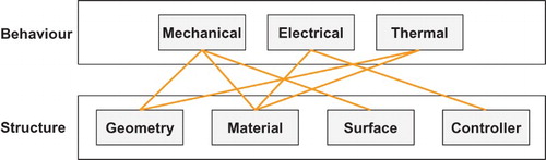
Figure 5. Functional elements and links of the diesel engine.
The functional model follows most of the proposed functions and flows from the reconciled functional basis. However, in some cases, it was decided to be more precise, and in other cases, less precise. For example, on the one hand, while Hirtz et al. (Citation2002) used general functions such as Import liquid, it was decided to use here a more precise function description such as Import fuel to locate subfunctions. On the other hand, functions such as Start engine (F1) are kept less detailed than suggested by the reconciled functional basis because their elementary level is less relevant for the change model of the diesel engine.
(2v) Map the function-behaviour (F-B) links: The functional elements (subfunctions) were first linked to the components and then further specified into undirected links between functional and behavioural elements. As with the S-B links, these links were quantified using standard values of 0.5 for change likelihood and 0.1 for change impact.
4.3. Compute combined change risk
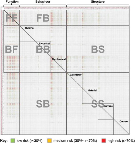
Finally, all links and elements were put together to complete the FBS Linkage scheme for the diesel engine. This network was imported into the CAM software and the Forward CPM algorithm was applied to calculate the combined risk profile considering six steps of propagation. The detailed results are represented in the risk MDM in . The shading colour indicates the risk value: the darker (redder) the cells, the higher the risk. Although, the diagram resolution is too low for reading the details, the screenshot indicates the density distribution of the MDM.
Figure 6. Combined risk MDM for the diesel engine (colour online).
4.4. Use the model
The combined risk MDM in shows the dependencies between the functional, behavioural, and structural layers in multiple attribute dimensions and can help understand how changes propagate within the system. It is more populated than the direct likelihood or impact MDMs and has only a few empty cells because it combines direct and indirect connections.
For high-level analyses, the behavioural and structural layers of the combined risk MDM were aggregated using the maximum operator (=max{}) to obtain the component–component risk design structure matrix (DSM) in . This aggregated matrix includes the maximum combined risk values of the three behavioural and four structural attribute design structure matrices (DSMs) as well as the 24 square domain mapping matrices (DMMs) between them as depicted in . Thus, this result represents the worst-case scenario of change propagation; the DSM does not differentiate between the types of change (e.g. Geometry, Material, or Electrical behaviours) and assumes that all component attributes are affected simultaneously while taking the highest risk into account. Such a DSM helps to identify risk absorbers and multipliers (Eckert, Clarkson, and Zanker Citation2004) and compare the component risk profiles to each other (Keller, Eckert, and Clarkson Citation2009).
Figure 7. Aggregated combined risk DSM for the diesel engine (FBS Linkage) (in %) (colour online).
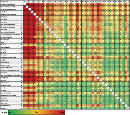
The colour scale indicates the risk values as follows: Green is used for low risk, yellow for medium risk, and red for high risk. The overall average of the risk values is 24.9%, with a distribution of {min; 0.25-quantile; median; 0.75-quantile; max} = {0; 5%; 14%; 34%, 100%} and a population-density (i.e. actual risk values above zero divided by possible links) of 98.3%. The distribution is right-skewed and the majority of the links have low risk values. The colour scale of indicates that the components C1–C12 are critical towards receiving changes from other components (i.e. rows 1–12) as well as imposing changes to other components (i.e. columns 1–12) and especially among each other (cells within rows and columns 1–12). This result is expected because these components form the engine core and include the majority of connectivity in the engine. The links between most of the other components (C13–C42), which are rather peripheral components, are less critical. The high population density of this DSM reflects the view that the whole diesel engine is one fully integrated system and suggests that all components are interlinked to each other. A change in one component may affect almost any other component.
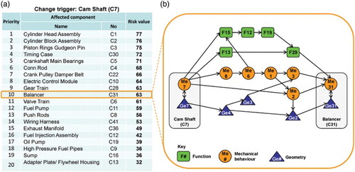
This combined risk DSM of the FBS Linkage method can be used as a starting point of the change propagation investigation. For every component, a prioritised list of all affected components can be prepared based on this DSM. Every line in that list can then be further detailed and the risk numbers can be traced back to causal propagation paths on the attribute level using the FBS Linkage MDM and network. For instance, (a) shows such a prioritised change risk list for Cam Shaft (C7). From the list, it can be seen that Cylinder Head (C1) and Block Assembly (C2) and Piston-Rings-Gudgeon-Pin (C3) are at highest risk if the Cam Shaft changes. Usually, the components at high risk are closely interconnected to the change trigger and the impact on them is preeminent to designers. However, the links to the components in the middle range of the risk values are not always obvious because these components are usually only indirectly connected. Such a prioritised list can help avoid oversight of change impacts on those components. (b) details the links between Cam Shaft (C7) and Balancer (C31). This propagation path analysis provides a rationale for the risk value and explains how the change trigger affects the target.
Figure 8. (a) Prioritised change risk list for Cam Shaft and (b) selected change propagation paths from Cam Shaft to Balancer (colour online).
5. Evaluation
An evaluation workshop was conducted at Perkins Engines Company Limited in Peterborough with 10 engineers. An overview of the participants, their positions, and their years of experience is presented in .
Table 2. Interview participants.
The first author presented the method and demonstrated the corresponding model to the industry experts. All experts were new to the method. Engineer I was involved in the development of the original CPM in 2004. All the others had not come across the CPM. Questions raised during the presentation were answered, and ambiguities and open issues were clarified to ensure that the experts sufficiently comprehended the method. Then, they were asked to verbally assess the method. The workshop took two hours and was recorded completely. The recordings were transcribed and analysed to abstract the key arguments. The evaluation results were sent to the participants by e-mail to allow them to revise any possible transcription errors and to ensure that their arguments were considered completely and correctly.
Representatively for the evaluation, a few quotes are presented here:
Engineer I, who supported the development and testing of the original CPM from the Perkins side, commented:
This is a combination of robust engineering, functional models, boundary elements, understanding the linkages, and understanding of energy flows which is fundamental but not well understood. Generating this model teaches you how the product works. ‘How does the energy flow?’, ‘What goes on in there?’ And then you can understand what happens to all interfaces. This model basically – very nicely, especially since you brought the FBS side into it – gives you the user experience understanding [ … ] and it links into the structural behaviour and flow of energy, so you can understand how does thermal energy leave from the combustion system to flow through the structure and how likely is it that it will have an effect on this component over here. Why that is so critical is that a change over here affects a component over there – and it is not intuitive.
Engineer J commented:
Like FMEAs, this actually enables people with less experience to pull on the experience from everybody else. The real value of this in my mind is that, if this is done upfront with a team of absolute experts, so it's there. Then as the program explodes, everybody can jump in there immediately and get it.
Engineer A continued:
If you do it right the first time, you save valuable management time. [ … ] Once you got a network, you could use it on several platforms. [ … ] You still have to come back to adapt it to other platforms, and the changes between two different platforms could be dramatically. However, this reduces the number of required experts in the subsequent meetings. Instead of calling all the experts, you can call only the experts that are needed for the specific components [ … ] and have smaller meetings.
Engineer H commented:
It just points you in a direction. For me, once you get something like that [a list of affected components] and it looks a bit strange, then I go, ‘well, that's actually not what I expected. what's driving that?’ This is effectively what an FMEA does anyway. I don't hang up on the accuracy of the number. The number is not irrelevant but it's the principle.
Engineer G added:
That is what we would get from the boundary diagrams in combination with the FMEAs. And that's exactly how we should structure our FMEAs with reference to those structures. The only bit that it doesn't give you is the quantified bit. It just says that these things are connected, you should consider it.
Engineer B noted:
I think we are also worrying a bit too much about how we apply it to our daily business, right here and right now, and how we start using it, [ … ] rather than, as a model, would it work if you had something simpler.
Engineer C concluded:
As a method to reduce the required experience needed, I definitely say that the concept is working.
Engineer D explained:
When you get to a very complex system such as an engine, the model starts to get very, very big, and the required resources to update and maintain it get very, very big. It comes to a point, where ‘does the return value justify the amount of input?’ It's not like that we haven't got something that does at least some part of the job. But when you shrink it down to a system like a Turbocharger or an Oil Pump I wonder if it has more value. Then, you could do it in more detail. You can be very much more specific.
Engineer E said:
I think it would be good to see such a model integrated on top of our existing PLM systems. I think that would be an ideal situation. [ … ] So we would be able to understand, ‘ok, I am changing this part, it's going to have a risk on these particular parts’.
Engineer J stated:
I think one of the key things is the generation of the model. I am not sure how sophisticated it is, but I mean it can be quite complicated, requiring a lot of understanding. The simpler it is to create, the more likely it is to be used.
Engineer A added:
Maybe a software can facilitate this, with an interface that would break it down.
Engineer D concluded:
I think the method is good. It is going to provoke a few thoughts and a few discussions about our existing processes, at the very least, and plus a few ideas about the future maybe.
Engineer G added:
There are some ideas that we can reuse on our existing processes. I'd like to think that we could go to a full model at some point, but I think to release the resources for that, you would have to demonstrate, what is the outcome value of this to justify the upfront resources.
To summarise the evaluation, the first author read through the manuscript and abstracted the arguments to create a separate list of distinct arguments for each expert. Then, the arguments were compared among the experts, and similar ones were clustered. For the clusters, a comprehensive description was generated by combining or rephrasing the arguments. The result is presented in , where the arguments are categorised into ‘praised advantages’ or ‘improvement suggestions’ and exhibits are provided by corresponding quotes from the engineers. As can be seen from this overview, the advantages of the FBS Linkage method that the industry experts praised include its capability to: (1) provide a checklist, (2) capture and transfer knowledge, (3) show how the product works, (4) be adapted to other platforms, and (5) improve current practice and processes. However, there are also a number of limitations that they pointed out and that need to be considered in the future improvement of the method. The main issues to be addressed include: (1) the scope of the method might be narrowed allowing it to be more specific for systems, (2) the amount of effort to build the model could be reduced, and (3) the method could be integrated to other systems in order to be updated regularly.
Table 3. Overview of the key arguments of the industry experts about the FBS Linkage method.
At the end of the workshops, the experts were given a questionnaire including 25 requirements for ECM methods and their descriptions, and they were asked to rate the method against the requirements using a scale from 1 to 5 as follows: 1 (strongly disagree), 2 (disagree), 3 (neither agree nor disagree), 4 (agree), and 5 (strongly agree). These requirements were developed and discussed in (Hamraz et al. Citation2013b), following five steps: First, publications describing 54 ECM methods were reviewed to draw a long list of requirements from literature. Second, requirements based on case-study experience were added to the list. Third, the resulting long list of requirements from both literature and case studies was studied to identify and remove duplicates and produce a list of unique requirements. Forth, a contextual framework consisting of the five requirement categories related to Input, Output, Change propagation method, Modeller, and User was developed and the list of unique requirements was organised into these five categories. Finally, the list of organised requirements was reviewed and further adjusted and completed to obtain the 25 requirements.
A summary of the assessment results is given in .
Table 4. Rating of the FBS Linkage method against requirements.
The assessment results in show that overall the experts agree that the FBS Linkage method meets the requirements (unweighted average score: 3.7 out of 5.0). Overall, the result of this survey is in line with the verbal evaluation during the workshop. In principle, the engineers favour the FBS Linkage method. The requirements they ranked the highest are: 19. Product modelling capability (4.3), 3. Range of levels of decomposition covered (4.2), 22. Change containment capability (4.2), and 24. Numerical analysis capability (4.2). These advantages are related to the level of detail modelled by the FBS Linkage method and to the numerical approach undertaken to estimate risk profiles. However, with respect to the following requirements, they are relatively reserved: 4. Ease of model building (2.4), 5. Availability of information to build the model (3.2), and 14. Flexibility (3.2). These limitations are concerned about the complexity and effort required to develop a model.
This interview and questionnaire-based assessment is indicative and subject to expert opinions. A few limitations of this assessment should be emphasised here. To reduce subjectivity, only external evaluators who were not involved in model building were selected. The evaluation was solely based on the method details presented to the experts by the first author during the workshop. These details were presented in form of slides and elaborated the modelling approach and the generated output as partly presented in Sections 3 and 4. As a result, some of the requirements which are related to working directly with the model and applying it to actual tasks were assessed based on limited evidence. Model verification (i.e. is it correct?) was undertaken throughout the model-building process, but was not explicitly covered in this workshop. However, the experts were presented with diagrams of all three layers of the FBS network including the functional block diagram and had time to comprehend the logic and check for plausibility and completeness before they judged the method and completed the questionnaire. In this context, it should be noted that the assessment could also be distorted because of the influence of the presentation itself on the evaluation. Furthermore, the assessment was performed in the presence of the author. This allowed the experts to ask questions and clarify any issues they had with the questionnaire or the understanding of the method, but anonymity was not provided. Thus, the experts may have been intimidated by the author and assessed the method more positively.
Overall, the evaluation was insightful and helped to reveal strengths and weaknesses of the method and laid the foundation for further improvement. However, it can only be considered as an early stage of model validation and does not replace an evaluation based on an actual implementation in practice and application on real data. That way, not only the feasibility and performance of the tool can be evaluated but also its usability in real-life conditions. Further validation of the method in industry would be required and will be part of our future work.
6. Summary and conclusion
ECs are essential and their management can determine the commercial success of products. To support ECM, the FBS Linkage method was developed. This method enhances the approved concept of CPM by introducing an FBS scheme into its product model. Essentially, this enhancement enables modelling the product in greater detail and allows for more detailed analysis of changes.
This paper aimed at providing an industrial evaluation of the method to pave the way for further improvement directions. To do so, first, the FBS Linkage method was outlined, before it was applied to model a diesel engine design. Then, a workshop was conducted with 10 engineers from the diesel engine manufacturer to evaluate the method.
Overall, the engineers favoured the FBS Linkage method and ranked it on average 3.7 out of 5.0 against a set of 25 different requirements for ECM methods. However, the experts pointed out some areas for further improvements as well. They praised the method's capabilities to: (a1) provide a checklist of change affected parts and thereby ensure that nothing is missed out, (a2) capture and transfer knowledge from experts to the whole organisation, (a3) show how the product works and promote a better understanding of the system interactions, (a4) be adapted to other platforms, and (a5) improve current practice and processes of ECM. However, there are also a number of limitations that the practitioners pointed out and that need to be considered in the future improvement of the method. (b1) The engineers advised to reconsider the scope of the method and pointed out that although it would be good to model the whole product, it might be even more useful for such a method to focus only on one system and model it more precisely to provide more specific guidance. (b2) They warned about the amount of input and effort required to build FBS Linkage models and suggested to find out ways to simplify or reduce it. (b3) Furthermore, they suggested that the method could be linked to other systems in order to be regularly updated and integrated into the applied systems. These issues will be addressed in our future work. To recommend an optimal scope of the method (i.e. b1), models of different levels of granularity could be assessed against each other in terms of cost and benefit. Furthermore, the sensitivity of the model output to its input could be investigated to make a recommendation on the amount and quality of input information required for a cost-benefit optimised model. To reduce the model-building effort (i.e. b2), the method will be fully implemented into the software program CAM. This software tool would facilitate further case studies and help continuous improvement and industrial acceptance of the method. The software tool could then be gradually enhanced to increase automation in model building. The diesel engine model presented in this paper was manually built and mostly created from scratch. The required information was gathered from technical product documentations and expert interviews. Techniques which facilitate or even partly automate information gathering and model building can significantly reduce the model-building effort. These may include knowledge-based techniques which use information from existing models to support building of new models as well as automated reading and analysing of technical documents. In this context, building a repository of FBS Linkage models may be very helpful. It could be investigated whether the (reconciled functional basis) Design Repository of the Design Engineering Lab at Oregon State University could be used for this purpose. Finally, to investigate how the method could be linked to other systems (i.e. b3), more research must be conducted to identify possible interfaces between FBS Linkage and product life cycle management software and determine interface requirements for the integration. Furthermore, the dimensions of the model – functions, behaviours, and structures – could be extended to incorporate other domains such as organisation, design process, manufacturing and factory requirements, and supply chain. These additional layers play an important role in companies with significant production rates and would allow a more comprehensive analysis of EC propagation.
Acknowledgements
The authors would like to thank Dr. Nicholas H.M. Caldwell, Tom W. Ridgman, Athanasios Dimopoulos and Perkins Engine Co. Ltd. for enabling the diesel engine case study and especially the dedicated Perkins engineers for evaluating the method and providing valuable industry feedback.
Disclosure statement
No potential conflict of interest was reported by the authors.
Additional information
Funding
References
- AIAG. 2012. Standardized Engineering Change Management Process Significantly Reduces Cost and Inefficiency. AIAG Homepage. Accessed February 17, 2015, http://www.aiag.org/staticcontent/files/Success-Stories/Engineering-Change-Management.pdf
- Albers, A., A. Braun, E. Sadowski, D. C. Wynn, D. F. Wyatt, and P. J. Clarkson. 2011. “System Architecture Modeling in a Software Tool Based on the Contact and Channel Approach (C&C-A).” Journal of Mechanical Design 133 (10), article id 101006 (8 pp.). doi:10.1115/1.4004971
- Chandrasegaran, S. K., K. Ramani, R. D. Sriram, I. Horváth, A. Bernard, R. F. Harik, and W. Gao. 2013. “The Evolution, Challenges, and Future of Knowledge Representation in Product Design Systems.” CAD Computer Aided Design 45 (2): 204–228. doi: 10.1016/j.cad.2012.08.006
- Chen, L., A. Macwan, and S. Li. 2007. “Model-based Rapid Redesign Using Decomposition Patterns.” Journal of Mechanical Design 129 (3): 283–294. doi: 10.1115/1.2406099
- Chen, Y. M., W. S. Shir, and C. Y. Shen. 2002. “Distributed Engineering Change Management for Allied Concurrent Engineering.” International Journal of Computer Integrated Manufacturing 15 (2): 127–151. doi: 10.1080/09511920110047181
- Clark, K. B., and T. Fujimoto. 1991. Product Development Performance: Strategy, Organization, and Management in the World Auto Industry. Boston, MA: Harvard Business School Press.
- Clarkson, P. J., C. Simons, and C. M. Eckert. 2004. “Predicting Change Propagation in Complex Design.” Journal of Mechanical Design 126 (5): 788–797. doi: 10.1115/1.1765117
- Cohen, T., S. B. Navathe, and R. E. Fulton. 2000. “C-far, Change Favorable Representation.” CAD Computer Aided Design 32 (5): 321–338. doi: 10.1016/S0010-4485(00)00015-4
- Eckert, C., T. Alink, A. Ruckpaul, and A. Albers. 2011. “Different Notions of Function: Results From an Experiment on the Analysis of an Existing Product.” Journal of Engineering Design 22 (11–12): 811–837. doi: 10.1080/09544828.2011.603297
- Eckert, C. M., P. J. Clarkson, and W. Zanker. 2004. “Change and Customisation in Complex Engineering Domains.” Research in Engineering Design 15 (1): 1–21. doi: 10.1007/s00163-003-0031-7
- Far, B. H., and A. H. Elamy. 2005. “Functional Reasoning Theories: Problems and Perspectives.” Artificial Intelligence for Engineering Design, Analysis and Manufacturing (AIEDAM) 19 (2): 75–88.
- Fricke, E., B. Gebhard, H. Negele, and E. Igenbergs. 2000. “Coping with Changes: Causes, Findings, and Strategies.” Systems Engineering 3 (4): 169–179. doi: 10.1002/1520-6858(2000)3:4<169::AID-SYS1>3.0.CO;2-W
- Fricke, E., and A. P. Schulz. 2005. “Design for Changeability (dfc): Principles to Enable Changes in Systems throughout Their Entire Lifecycle.” Systems Engineering 8 (4): 342–359. doi: 10.1002/sys.20039
- Gero, J. S. 1990. “Design Prototypes: A Knowledge Representation Schema for Design.” AI Magazine 11 (4): 26–36. doi: 10.1109/62.63160
- Goel, A. K., S. Rugaber, and S. Vattam. 2009. “Structure, Behavior, and Function of Complex Systems: The Structure, Behavior, and Function Modeling Language.” Artificial Intelligence for Engineering Design, Analysis and Manufacturing (AIEDAM) 23 (1): 23–35. doi: 10.1017/S0890060409000080
- Goel, A. K., and E. Stroulia. 1996. “Functional Device Models and Model-Based Diagnosis in Adaptive Design.” Artificial Intelligence for Engineering Design, Analysis and Manufacturing (AIEDAM) 10 (4): 355–370. doi: 10.1017/S0890060400001670
- Hamraz, B., N. H. M. Caldwell, and P. J. Clarkson. 2013a. “A Holistic Categorisation Framework for Literature on Engineering Change Management.” Systems Engineering 16 (4): 473–505. doi: 10.1002/sys.21244
- Hamraz, B., N. H. M. Caldwell, and P. John Clarkson. 2012. “A Multidomain Engineering Change Propagation Model to Support Uncertainty Reduction and Risk Management in Design.” Journal of Mechanical Design 134 (10): 100905.01–14. doi: 10.1115/1.4007397
- Hamraz, B., N. H. M. Caldwell, D. C. Wynn, and P. J. Clarkson. 2013b. “Requirements-based Development of an Improved Engineering Change Management Method.” Journal of Engineering Design 24 (11): 765–793. doi: 10.1080/09544828.2013.834039
- Hamraz, B., O. Hisarciklilar, K. Rahmani, D. C. Wynn, V. Thomson, and P. J. Clarkson. 2013c. “Change Prediction Using Interface Data.” Concurrent Engineering 21 (2): 139–154. doi: 10.1177/1063293X13482473
- Helms, B., and K. Shea. 2012. “Computational Synthesis of Product Architectures Based on Object-Oriented Graph Grammars.” Journal of Mechanical Design 134 (2), 021008 (14 p). doi:10.1115/1.4005592
- Helms, B., K. Shea, and F. Hoisl, 2009. “A Framework for Computational Design Synthesis Based on Graph-Grammars and Function-Behavior-Structure.” ASME Design Engineering Technical Conference (DETC'09), San Diego, CA, USA.
- Hirtz, J., R. B. Stone, D. A. Mcadams, S. Szykman, and K. L. Wood. 2002. “A Functional Basis for Engineering Design: Reconciling and Evolving Previous Efforts.” Research in Engineering Design 13 (2): 65–82.
- Huang, G. Q., and K. L. Mak. 1999. “Current Practices of Engineering Change Management in UK Manufacturing Industries.” International Journal of Operations and Production Management 19 (1): 21–37. doi: 10.1108/01443579910244205
- Janthong, N. 2011. “A Methodology for Tracking the Impact of Changes in (Re)designing of the Industrial Complex Product.” IEEE International Conference on Industrial Engineering and Engineering Management (IEEM'11), Singapore, December 6–9, 1058–1062.
- Jarratt, T. a. W., C. M. Eckert, N. H. M. Caldwell, and P. J. Clarkson. 2011. “Engineering Change: An Overview and Perspective on the Literature.” Research in Engineering Design 22 (2): 103–124. doi: 10.1007/s00163-010-0097-y
- Jarratt, T. a. W., C. M. Eckert, and P. J. Clarkson. 2004. “Development of a Product Model to Support Engineering Change Management.” Fifth International Symposium on Tools and Methods of Competitive Engineering (TMCE'04). Lausanne, Switzerland, April 13–17, 331–342.
- Keller, R. 2007. “Predicting Change Propagation: Algorithms, Representations, Software Tools.” PhD thesis, University of Cambridge.
- Keller, R., C. M. Eckert, and P. J. Clarkson. 2009. “Using an Engineering Change Methodology to Support Conceptual Design.” Journal of Engineering Design 20 (6): 571–587. doi: 10.1080/09544820802086988
- Kocar, V., and A. Akgunduz. 2010. “Advice: A Virtual Environment for Engineering Change Management.” Computers in Industry 61 (1): 15–28. doi: 10.1016/j.compind.2009.05.008
- Loch, C. H., and C. Terwiesch. 1999. “Accelerating the Process of Engineering Change Orders: Capacity and Congestion Effects.” Journal of Product Innovation Management 16 (2): 145–159. doi: 10.1016/S0737-6782(98)00042-3
- Ma, Y., G. Chen, and G. Thimm. 2008. “Change Propagation Algorithm in a Unified Feature Modeling Scheme.” Computers in Industry 59 (2–3): 110–118. doi: 10.1016/j.compind.2007.06.006
- Maier, A. M., and S. Langer. 2011. Engineering Change Management Report 2011: Survey Results on Causes and Effects, Current Practice, Problems, and Strategies in Denmark. Copenhagen: Technical University of Denmark, Department of Management Engineering.
- Ollinger, G. A., and T. F. Stahovich. 2004. “Redesignit – A Model-Based Tool for Managing Design Changes.” Journal of Mechanical Design 126 (2): 208–216. doi: 10.1115/1.1666888
- Pasqual, M., and O. L. De Weck. 2012. “Multilayer Network Model for Analysis and Management of Change Propagation.” Research in Engineering Design 23 (4): 305–328. doi: 10.1007/s00163-011-0125-6
- Prasad, B. 1997. Concurrent Engineering Fundamentals: Integrated Product Development. Upper Saddle River, NJ: Prentice Hall.
- Qian, L., and J. S. Gero. 1996. “Functions-Behavior-Structure Paths and Their Role in Analogy-Based Design.” Artificial Intelligence for Engineering Design, Analysis and Manufacturing (AIEDAM) 10 (4): 289–312. doi: 10.1017/S0890060400001633
- Rahmani, K., and V. Thomson. 2011. “Managing Subsystem Interfaces of Complex Products.” International Journal of Product Lifecycle Management 5 (1): 73–83. doi: 10.1504/IJPLM.2011.038103
- Rouibah, K., and K. R. Caskey. 2003. “Change Management in Concurrent Engineering from a Parameter Perspective.” Computers in Industry 50 (1): 15–34. doi: 10.1016/S0166-3615(02)00138-0
- Simons, C. S. 2000. “Change Propagation in Product Design: A Change Prediction Method.” MPhil, University of Cambridge.
- Terwiesch, C., and C. H. Loch. 1999. “Managing the Process of Engineering Change Orders: The Case of the Climate Control System in Automobile Development.” Journal of Product Innovation Management 16 (2): 160–172. doi: 10.1016/S0737-6782(98)00041-1
- Umeda, Y., M. Ishii, M. Yoshioka, Y. Shimomura, and T. Tomiyama. 1996. “Supporting Conceptual Design Based on the Functions-Behavior-State Modeler.” Artificial Intelligence for Engineering Design, Analysis and Manufacturing (AIEDAM) 10 (4): 275–288. doi: 10.1017/S0890060400001621
- Umeda, Y., S. Kondoh, Y. Shimomura, and T. Tomiyama. 2005. “Development of Design Methodology for Upgradable Products Based on Functions-Behavior-State Modeling.” Artificial Intelligence for Engineering Design, Analysis and Manufacturing (AIEDAM) 19 (3): 161–182.
- Umeda, Y., H. Takeda, T. Tomiyama, and H. Yoshikawa. 1990. “Function, Behaviour, and Structure.” In Applications of Artificial Intelligence in Engineering, edited by J. S. Gero, 177–193. Berlin: Springer.
- Van Beek, T. J., M. S. Erden, and T. Tomiyama. 2010. “Modular Design of Mechatronic Systems with Function Modeling.” Mechatronics 20 (8): 850–863. doi: 10.1016/j.mechatronics.2010.02.002
- Van Beek, T. J., and T. Tomiyama. 2012. “Structured Workflow Approach to Support Evolvability.” Advanced Engineering Informatics 26 (3): 487–501. doi: 10.1016/j.aei.2012.05.003
- Wright, I. C. 1997. “A Review of Research into Engineering Change Management: Implications for Product Design.” Design Studies 18 (1): 33–39. doi: 10.1016/S0142-694X(96)00029-4
- Wynn, D. C., D. F. Wyatt, S. M. T. Nair, and P. J. Clarkson. 2010. “An Introduction to the Cambridge Advanced Modeller.” 1st International Conference on Modelling and Management of Engineering Processes (MMEP'10), Cambridge, July 19–20.