
 ?Mathematical formulae have been encoded as MathML and are displayed in this HTML version using MathJax in order to improve their display. Uncheck the box to turn MathJax off. This feature requires Javascript. Click on a formula to zoom.
ABSTRACT
Alloy material selection for sustainable, efficient, and cost-effective use in components is a key requirement for both power generation and aerospace sectors. Superalloys are manufactured using a combination of different elements, selected carefully to balance mechanical performance and environmental resistance to be used in a variety of different service conditions. Therefore, a fundamental understanding of each element is critical to alloy design. In this paper, the interaction of alloy chemistry, particularly chromium as a corrosion-resistant element along with titanium and molybdenum, and their effect on alloys performance for the relevant gas turbine industries were discussed. Based on the findings, the single-crystal alloy is found to be a better corrosion resistant alloy exhibited higher corrosion resistance in comparison to polycrystal alloys and proved that microstructure has a significant impact on alloy performance. This study also established that molybdenum level in chromia former alloys can significantly enhance the corrosion damage.
Introduction
Nickel-based superalloys for gas turbines used in aerospace and power generation industries operate in high-temperature environments, up to 1500°C [Citation1,Citation2]. Manufacturers select alloys with compositions to meet the performance requirements within these harsh conditions such as mechanical loads and thermal shock, hot corrosive gas environments and/or simultaneous mechanical and chemical changes, i.e. corrosion-fatigue [Citation3]. The turbine components experiencing these properties for a variable time periods depend on fight type within a specific environments. Therefore, the study of type I hot corrosion on these alloys can help manufacturers to better anticipate the corrosion rate of superalloys used in the turbines [Citation2,Citation3].
Hot corrosion damage can lead to component failure with potential serious consequences such as engine failure or plant shutdown. Hot corrosion occurs from a combination of the fuel burnt and salt present in the ingested air. This leads to the formation of molten salts deposits which trigger hot corrosion reactions [Citation4,Citation5]. Hot corrosion initiation could rapidly propagate, hence must be taken into account during the selection of elements for alloys manufacturing. There are two types of hot corrosion. Type I hot corrosion occurs within the range of temperatures between 800°C and 950°C, which correspond to a melting point temperature value of the alkali salts and leads to direct corrosion reactions. Type II hot corrosion occurs at lower temperatures (between 600°C and 750°C) and the morphology appears as localised pitting type attack [Citation2,Citation4–7]. This paper focuses on type I hot corrosion, and tests were carried out at 900°C to simulate this conditions.
Type I hot corrosion reaction is well known and documented [Citation5,Citation7,Citation8]. However, a further detailed study of a selection of alloys with different salt combinations will provide more information to the industry for better understanding of alloys effect on the corrosion mechanisms. Nickel-based superalloys are mostly used in gas turbines not only due to their high resistance to corrosion and oxidation reactions but also for their high mechanical stress resistance [Citation9,Citation10].
The aim of this paper is to understand the role of key elements such as chromium and aluminium on the degradation of alloys in type I hot corrosion. This paper focuses on a selection of three nickel-based superalloys: CMSX-4, IN713LC, and C1023. Chromium, being a key element, varies in its concentration for each alloy from 6.5 wt% for CMSX-4 to 15.5 wt% for C1023, and IN713LC has a concentration of chromium of 12.5 wt%. These concentrations allow us to establish role of chromium on type I hot corrosion rates in nickel-based superalloys. These alloys are also different within their manufacturing processes; CMSX-4 is single-crystal alloy, whereas IN713LC and C1023 are equiaxed polycrystal manufactured alloys.
Experimental
Three nickel-based superalloys were used in this study: CMSX-4, IN713LC, and C1023. The compositions are shown in .
Table 1. Composition of the three alloys compared (wt%).
Cylindrical specimens (length 10 mm, with diameter 8.5 mm) were used in this study. As the very first step, the samples were cleaned in an ultrasonic bath using acetone and isopropyl alcohol for 20 min each. Then, dimensions of each sample were measured with a digital micrometre with a resolution of ±1 μm.
The, samples were weighed and covered with deposits using a deposit-recoat process [Citation6] and placed in a furnace. The furnace temperature was maintained at 900°C. The samples were exposed in a furnace at a temperature of 900°C and samples were re coated with salt every 40 h. The test matrix including salts types, exposure period for each alloy is listed in .
Table 2. The test matrix.
lists the various exposure periods for each sample covered with various salts during the test.
Table 3. Time of exposure in hours.
lists the melting point temperatures of salts used or possibly formed in the hot corrosion tests in the paper.
Table 4. Melting point of salts used in hot corrosion tests [Citation11].
further illustrates each cycle, sample exposure of 40 h in a vertical controlled atmosphere furnace at 900°C. After 40 h of exposure in the furnace, the sample were weighed, resalted, and reweighed again. Each sample was salted using a deposit salt solution at a flux rate of 1.5 μg/cm2/h and placed on a hot plate at 180°C to be certain of the evaporation of the water.
Figure 1. Schematic of a cycle of exposure [Citation6].
![Figure 1. Schematic of a cycle of exposure [Citation6].](/cms/asset/e55714b0-1212-494c-bb40-1b81fee81a79/ymht_a_2188355_f0001_b.gif)
After the final exposure, the samples were weighed and prepared to be examined under the microscope. A polished cross-section was prepared through the centre of each of the samples using a bespoke jig and non-aqueous metallographic techniques (mounting, cutting, grinding, and polishing). The cross sections mounts were polished to 1-μm diamond grit.
Dimensional metrology method was used to determine metal loss values [Citation8,Citation12,Citation13]. Dimensional metrology image analysis technique is based on the optical microscope measured thickness of the samples after the exposures. The thickness was determined using the x–y coordinates of a series of 60 points at the border of the metal loss and internal damage as sound metal loss. Therefore, these 60 coordinates allowed determination of metal thickness after the exposures (metal loss) but also possible internal damages (sound metal loss).
From these distributions, the cumulative probability curves were plotted and median (50%) and extreme (96%) metal loss determined. These probability curves can be used to determine a corrosion rate for each alloy. A detailed description of the method is available in earlier published papers [Citation14,Citation15].
Scanning electron microscope (SEM) has been used to take images of the samples which were first coated with a 10 µm layer of gold. Energy dispersive X-ray (EDX) analysis was used to study the elemental profile and mapping for quantitative and qualitative chemical composition studies, respectively.
Results
Mass change data
illustrate the mass change data of all three superalloys (IN713LC, C1023 and CMSX-4) covered with sodium sulphate and sodium chloride for 160 and 240 h at 900° C.
Figure 2. Mass change data of alloys IN713LC, C1023, and CMSX-4 covered with salts deposits exposed to air + 300 vppm SOx gaseous atmosphere gas for 160 and 240 h at 900°C.
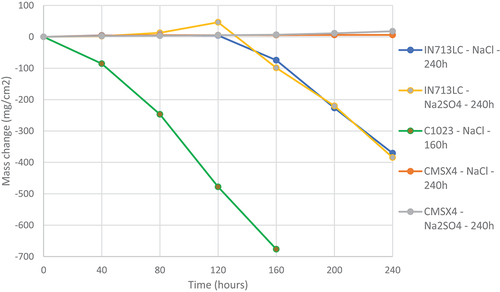
The mass change data for samples CMSX-4, covered with sodium sulphate or sodium chloride, exhibit very little mass change. However, IN713LC and C1023 showed significant mass loss. C1023 showed the highest mass loss values of ~700 mg/cm2 after 160 h of exposure. IN713LC interestingly showed approximately 400 mg/cm2 mass loss covered with both salts (sodium sulphate and sodium chloride) after exposure of 240 h. The mass change data for IN713LC showed a significant downward trend initiated at 120 h, which suggested a change from incubation to propagation. However, alloy C1023 showed rapid mass loss showing an incubation time shorter than 40 h, and rapid propagation.
demonstrates the effect of three salts (sodium chloride, sodium sulphate, and calcium chloride) on mass change data for IN713LC alloy.
Figure 3. Mass change data of alloys INC713-LC covered with various salts deposits exposed to air + 300 vppm SOx gaseous atmosphere gas for 240 h at 900°C.
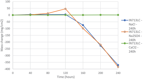
It is noticeable in that sodium sulphate and sodium chloride play a similar role on IN713LC and leads to a loss of mass of ~375 mg/cm2 after 240 h of exposure at 900°C. It is also noticeable that these two molten salts have the same incubation time of 120 h and the same corrosion rate after this time of incubation of respectively −141,34 mg/cm2/h for IN713LC salted with sodium sulphate and −127,79 mg/cm2/h for IN713LC salted with sodium chloride. However, calcium chloride seems benign with negligible mass change was observed for the sample during the 240 h of exposure of IN713LC sample. The sample of IN713LC salted with this calcium chloride salt showed no sign of corrosion. The data suggest that calcium chloride salt deposits are not as reactive, and contributing to corrosion damage, as the other salts. This behaviour suggests possible formation of CaSO4, which exhibit high melting points value~1460° C [Citation11,Citation16].
Optical images
The three alloys were observed under the optical microscope after 240 and 160 h of exposure and salted with sodium chloride.
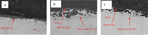
Images presented in show that both IN713LC and C1023 alloys suffer damage on the edge of the samples. However, the surface of CMSX-4 sample showed less degradations compared to the other two alloys. The loss of metal around the edges of both IN713LC and C1023 showed a similar morphology at scale/gas interface, whereas IN713LC showed a consistent internal layer suggests uniform internal damage around the specimen.
Figure 4. Optical images of cross-sections through alloy CMSX-4 (a) and IN713LC (b) covered with sodium chloride deposits exposed to air + 300 vppm SOx gaseous atmosphere gas for 240 h and C1023 (c) covered with sodium chloride deposits exposed to air + 300 vppm SOx gaseous atmosphere gas for 160 h at 900°C.
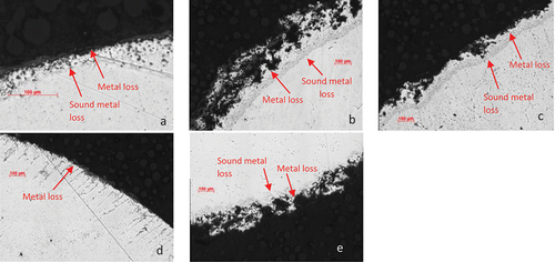
In , the images under the optical microscope showed that the degradation on the edge of IN713LC samples was more severe when salted with sodium chloride and sodium sulphate ()), respectively) in comparison with sample covered with calcium chloride salt (). This behaviour was also observed on C1023 samples, a significant metal loss on the edges for sample covered with sodium chloride () versus the sample covered with calcium chloride salt (). An interesting feature noticed is the internal damage on both alloys covered with calcium chloride salt has a different morphology.
Figure 5. Optical images of cross-sections through alloy IN713LC covered with (a) calcium chloride, (b) sodium chloride and (c) sodium sulphate deposits exposed to air + 300 vppm SOx gaseous atmosphere gas for 240 h and C1023 covered with (d) calcium chloride and (e) sodium chloride deposits exposed to air + 300 vppm SOx gaseous atmosphere gas for 160 h at 900°C.
Dimensional metrology
The dimensional metrology results provide the quantification of the corrosion performance of the different materials as they give a distribution of metal loss data for each material.
illustrates the damage distributions for alloys CMSX-4, IN713LC, and C1023 covered with sodium chloride deposits exposed to simulated hot corrosion type I combustion gases (air+300 vppm SOx) at 900°C. It is clearly seen that CMSX-4 showed much less corrosion damage than C1023 and IN713LC after 240 h of exposure. The dimensional metrology data shown in is in good agreement with mass change data in
Figure 6. Plot of the probability of sound metal loss of alloys CMSX-4 and IN713LC covered with sodium chloride salts exposed for 240 h and C1023, covered with sodium chloride salts exposed for 160 h to air + 300 vppm SOx gaseous atmosphere gas at 900°C.
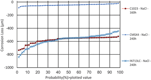
The median (50%) corrosion loss value for sample CMSX-4 covered with sodium chloride salt is approximately 45 µm, whereas median corrosion loss values for Inconel 713LC and alloy C1023 are almost 10 times higher (~550 µm). However, this is to be noticed that C1023 had a shorter exposure (160 h) compared to other alloys (CMSX-4 and INC713) exposed for 240 h.
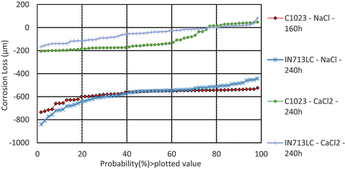
shows that samples covered with sodium chloride deposit exhibited significantly higher metal loss values. The median metal loss values for both alloys (C1023 and IN713LC) was observed as high as ~550 µm. However, when same alloys (INC713 and C1023) were covered with calcium chloride deposits, the median metal loss values were found to be much lower (~160 and~40 μm, respectively). The mass change data for IN713LC (in ) are also in line with these metal loss data (i.e. higher mass loss value when covered with sodium chloride salt).
Figure 7. Plot of the probability of sound metal loss of alloys C1023, and IN713LC covered with sodium chloride and calcium chloride salt deposits exposed for 160 and 240 h to air + 300 vppm SOx gaseous atmosphere gas at 900°C.
SEM images and EDX mapping
illustrate the cross-sections through the scales formed on chromia former alloy C1023 and single-crystal alloy CMSX-4 covered with sodium sulphate salt deposits after exposure for 160 and 240 h respectively at 900°C. The cross-section images for C1023 show no external scales are present and suggested the scales are likely to be spalled off the surface. An interesting feature noticed is the significant internal patchy appearance within each image in suggests the propagation of internal attack within the polycrystal alloy is irregular probably initiating a local scale breakdown and then propagating. shows the cross-section images for alloy CMSX-4 is thinner and more uniform scale forms compared to alloy C1023, which is also in agreement with mass change data. The internal damage is also noticeable underneath the thin scales within the alloys, suggesting an internal sulphidation with broad front attack (typical type I hot corrosion mechanism).
Figure 8. BSE images of alloy C1023 covered with sodium chloride salt deposits exposed to air + 300 vppm SOx gaseous atmosphere gas for 160 h.
Figure 9. BSE images of alloy CMSX-4 covered with sodium sulphate salt deposits exposed to air + 300 vppm SOx gaseous atmosphere gas for 240 h.
shows the cross-sectional images of IN713LC covered with calcium chloride and sodium chloride salt deposits exposed to air+300 vppm SOx gaseous atmosphere gas for 240 h.
Figure 10. BSE images of IN713LC covered with (a–c) calcium chloride and (d–f) sodium chloride salt deposits exposed to air + 300 vppm SOx gaseous atmosphere gas for 240 h.
(a–c; cross-sectional images of IN713LC) shows the presence of an outer scales and internal corrosion within the alloy at the scale alloy interface. Clearly, the calcium chloride deposits have entered propagation after 240 h with a mix mode of internal attack showing both internal oxidation and sulphidation. The attack is, however, much less advanced than with sodium chloride salt. (d–f) shows the attack under an initial sodium chloride deposits is much severe. It is evident that the outer oxide has spalled (it is absent) and alloy had an internal irregular patchy internal oxidation degradation. It is also to be noticed that morphology of internal degradation of alloy IN713LC in (a–c) is similar to internal degradation morphologies shown in for alloy C1023. However, the exposure period of C1023 alloy sample was only 160 h compared to 240 h exposure of IN713LC alloy.
It can be seen in that C1023 exhibits deep internal attack after a short exposure of 160 h in comparison to longer exposure for CMSX-4 and INC713 in . Chromium level in alloy C1023 (15 wt %) is higher compared to chromium level (10%) in IN713LC. Chromium addition into alloys is known for its property as a corrosion resistance, element. However, results suggested that chromium content is not the deciding factor for corrosion rate here. Molybdenum is the (refractory) element with highest concentration of 8.5% in C1023 compared to 4.3 and 0.6% in INC713 and CMSX-4 alloys respectively. Literature suggested [Citation17,Citation18] that addition of molybdenum is beneficial at lower temperature. However for some high temperature applications, molybdenum additions can result in catastrophic attack due to formation of low melting point, volatile and non-protective oxide MoO3, and its incorporation in the deposits to give acid fluxing [Citation18,Citation19].
Figure 11. EDX mapping of IN713LC covered with sodium chloride salt deposits exposed to air + 300 vppm SOx gaseous atmosphere gas for 240 h.
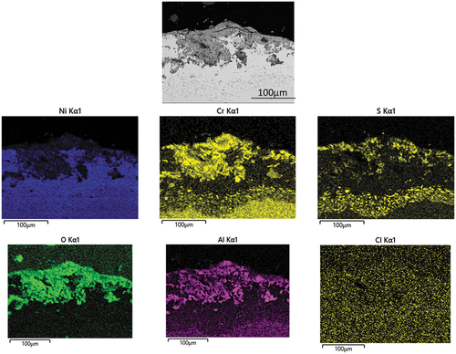
The EDX mapping in demonstrates the elemental distribution around the alloy/scale interface. The BES image shows obvious internal alloy degradation The role of sulphur in the corrosion attack mechanism is confirmed by the detection of an S-rich layer concentrated underneath the inner scale, showing that is penetrating through the outer scale layers. In the outer region oxygen, aluminium and chromium are detected. It is interesting to notice that chlorine is not present at the alloy surface. The enrichment of aluminium and chromium and oxygen suggested the well-known corrosion resistance oxide formations.
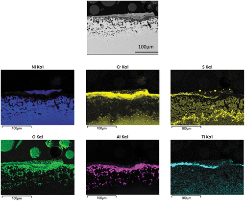
shows EDX mapping of INC 713 exposed to hot corrosion type I conditions for 240 h. It is clearly shown that oxygen is distributed throughout the scale. Chromium enrichment as a thick layer is clearly identified under the corrosive deposits. High level of sulphur was detected underneath the internal damage most probably as chromium sulphide. Significant patches rich in aluminium are also present within the same region most probably alumina. Titanium is also evident at the top region of the oxide/sulphide scale. The backscattered electrons (BSE) image shows the internal degradation has significant porosity.
Figure 12. EDX mapping of IN713LC covered with calcium chloride salt deposits exposed to air + 300 vppm SOx gaseous atmosphere gas for 240 h.
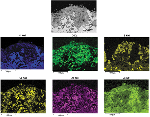
illustrates EDX mapping of a cross section through alloy C1023 after 160 h exposure under type I hot corrosion test. It is also interesting to notice that the EDX maps of are very similar. These maps show the distribution of oxygen throughout the scale. Significant presence of aluminium and chromium was found with in the inner oxidation and sulphidation zone. EDX maps also shows presence of cobalt which is comparatively localised. Pits in suggesting chromium sulphides attack could preferentially occur. Moreover, during this detailed investigation, chlorine was not detected. The morphology suggested the formation of pits within the alloy which propagated later into in irregular patches sideways along the grain boundaries then laterally to form broad front attack.
Figure 13. EDX mapping of C1023 salted covered with sodium chloride salt deposits exposed to air + 300 vppm SOx gaseous atmosphere gas for 160 h.
Discussions
Alloys comparisons
The key difference between the alloys is that CMSX-4 is a single-crystal alloy while IN713LC and C1023 are equiaxed grains alloys. The mode of attack is different between these two classes of alloys. Comparison between , with 9 and (d–f) underlines the fact that within a single-crystal alloy, the corrosion occurred as a uniform layer at the surface of the sample. Whereas IN713LC and alloy C1023 exhibit preferential attack forming local corrosion product and suggested a nonlinear progression in patches of corrosion inside the sample possibly initiating at grain boundaries. Sui et al. [Citation20] reported similar work on nickel-based polycrystal super alloys in high-temperature corrosive conditions under strain conditions. One of the key conclusions if their studies was that grain boundary and local stress concentration region as the surface defects are usually the sites where corrosion pit preferentially begin. It was further highlighted in their work that corrosion resistance is essentially dependent on defects’ density at the surface of alloy. In this paper, the test was carried out in static corrosion conditions under no strain. However, both IN713LC and C1023 being polycrystal alloys exhibit grains boundaries and resulted higher corrosion damage than single-crystal alloy CMSX-4 [Citation20]. It is likely that structural defects make available pathways for diffusion of chromium to the external oxide and inward transport of oxygen and sulphur. The crystalline defects such as vacancies and grains contribute in controlling the transport of element species through diffusion, leading to higher oxidation and corrosion rates [Citation21].
It was also observed from that IN713LC and C1023 differ in their incubation time; thus the onset of propagation not only depends on the microstructure but also on the alloy chemistry. indicate that CMSX-4, when covered with sodium chloride or sodium sulphate, shows greater degradations; thus, CMSX-4 is not resistant to corrosion but, has an incubation time greater than 240 h of exposure at 900°C. Both IN713LC and C1023 alloys are chromia formers. These chromium oxides on the layers help them to prevent corrosion, but this is not quite effective. Presence of grains and the level of refractory elements within both polycrystal alloys are deciding factors. Park and co-workers [Citation22] studied the role of chromium, aluminium, and the effect of refractory elements on nickel-based super alloys in high-temperature oxidation environment. Their findings suggest that the appropriate level of refractory elements such as molybdenum is key to have alloys minimum oxidation rates or it may hinder the formation of chromia or alumina, as well as the volatilisation of their oxides. High valence ion of molybdenum is likely to have consumed high level of oxygen and formed molybdenum oxides. Molybdenum oxides can be readily fluxed by alkali salt forming acid melts containing sodium molybdate increasing the rate of type I hot corrosion [Citation19]. Subsequently, it decreased the formation of protective alumina and chromia which is reflected in this study where alloy C1023 with higher chromium level underperformed in comparison to a lower chrome alloy IN713LC.
Molten salts comparisons
The various salts used in this study have different impacts on each alloy. Sodium chloride and sodium sulphate seem to have a similar corrosion damage results (as shown in mass change data), whereas samples covered with calcium chloride salts ( mass change data) show a more minimal effect on the corrosion of the alloys.
This was observed on that IN713LC has exhibited the same mass change when exposed to sodium chloride and sodium sulphate. Sodium chloride may react with SO2/SO3 in the gas phase, forming a corrosive environment leading the formation of sodium sulphate and hydrogen chloride. This reaction could explain why sodium chloride and sodium sulphate have the same impact on the alloy. We can also conclude from that the sulphation of sodium chloride to sodium sulphate chemical reaction decreases the incubation period, i.e. 120 h. Indeed, the two curves corresponding to sodium chloride and sodium sulphate are similar and correspond to the same molten salt corroding the alloy, i.e sodium sulphate. This reaction sequence likely to cause the formation of hydrogen chloride [Citation2,Citation23] which may be lost to the gaseous environment.
The second could leads to further corrosion due to release of chlorine and its reaction with the alloy constituents to form metal chlorides and other corrosive compounds. These react with the oxygen to form a porous layer at the surface of the alloy releasing chlorine and continue the degradation of alloy through its grain boundaries (active oxidation) [Citation24,Citation25].
However, chlorine is very volatile element, especially at 900°C [Citation26,Citation27]. Chlorine is not part of the chemical process of degradation of the alloy, as seen in , because it has evaporated before attacking the alloy.
show some attack with calcium salts. However, it was observed in that calcium chloride salt seems to be benign and have no effect on mass change. It can be expected a loss of mass when salting the alloy with calcium chloride because it forms chlorine. The chemical reaction of calcium chloride in a corrosive environment could be
The melting point of calcium sulphate is at 1,460°C; thus, we can affirm that this component is not involved in the corrosive reaction of calcium chloride. However, chlorine can be expected to deteriorate the alloy in a corrosive environment. In that case, we would observe in a loss of mass of the IN713LC when salted with calcium chloride. However, chlorine is very volatile element, especially at 900°C [Citation26,Citation28].
The results show that calcium chlorides corrode nickel-based alloys under the conditions of this study. It can be concluded that calcium chloride has a longer incubation period. This incubation period must be at least more than 240 h (the maximal time of exposure of the samples observed in [a–c]).
Conclusion
The studies can be summarised into the following conclusion:
Equiaxed alloys (IN713LC and C1023 alloys) exhibit a different development of degradation than single-crystal alloys (CMSX-4). Corrosion is propagating through grain boundaries and form local attack, pits of corrosion, which was not uniform and were not found in CMSX-4 alloy. This concludes that the degradation exacerbated through grain boundaries is more destructive than corrosion of single-crystal CMSX-4 alloy. This is considered to have a bigger impact than chromium content.
IN713LC presents a 120-h period of incubation, while C1023 has an incubation period estimated between 20 and 25 h, and showed a rapid degradation.
High level of molybdenum in alloy C1023 likely to increase the fluxing attack of the chromia and contribute early initiation and enhanced propagation.
CMSX-4 has a longer incubation period than 240 h; the time of exposures in this test, however, is not fully resistant to corrosion damage.
The three superalloys form chromium sulphides as a result of sulphur penetration into the substrate. At the alloy interface, the formation of oxide scales of chromium and alumina were also found.
Calcium chloride salts under these conditions were found to be least corrosive compared to sodium sulphate and sodium chloride.
A uniform layer of corrosive product at the surface of samples was formed when corroded with calcium chloride.
The two other salts (sodium sulphate and sodium chloride) degrade the alloys with local pitting attack.
Sodium chloride is thought to rapidly transform into sodium sulphate and is the reason that both salts have a similar impact on the alloys.
Disclosure statement
No potential conflict of interest was reported by the authors.
References
- Morad A, Shash Y. Nickel base superalloys used for aero engine Turbine blades. Int Conf Appl Mech Mech Eng. 2014;16(16):1–22.
- Eliaz N, Shemesh G, Latanision RM. Hot corrosion in gas turbine components. Eng Fail Anal. 2002;9(1):31–43.
- Kolagar AM, Tabrizi N, Cheraghzadeh M, et al. Failure analysis of gas turbine first stage blade made of nickel-based superalloy. Case Stud Eng Fail Anal. 2017;8:61–68.
- Ma X, Shi H-J. On the fatigue small crack behaviors of directionally solidified superalloy DZ4 by in situ SEM observations. Int J Fatigue. 2012 Feb;35(1):91–98.
- Pettit F. Hot corrosion of metals and alloys. Oxid Met. 2011;76(1):1–21.
- Syed AU, Martinez FD, Roberts T, et al. Performance comparison between isothermal hot corrosion and in situ cyclic hot corrosion of nickel-based superalloys. Oxid Met. 2021;96(1):43–55. DOI:10.1007/s11085-021-10044-9
- Rapp RA. Hot corrosion of materials: a ̄fluxing mechanism? Corros Sci. 2002;44(2):201–221.
- Nicholls JR, Simms NJ, 1.20 - Gas Turbine oxidation and corrosion, Cottis B, Graham M, Lindsay R, Lyon S, Richardson T, Scantlebury D, and Stott C B H. editor. Oxford: Elsevier; 2010. pp. 518–540.
- Gurrappa I. The importance of hot corrosion and its effective prevention for enhanced efficiency of gas Turbines. Yashwanth IVS (editor). Rijeka: IntechOpen; 2015. 3. p. Ch.
- Sommitsch C, Radis R, Krumphals A, et al. 12 - microstructure control in processing nickel, titanium and other special alloys. In: Lin J, and Balint D, M. B. T.-M. E. in M. F. P. Pietrzyk, Eds. Woodhead publishing series in metals and surface engineering. Sawston, Cambridge: Woodhead Publishing; 2012. p. 337–383.
- Rowe JJ, Morey GW, Zen CS. The quinary reciprocal salt system Na, K, Mg, Ca/Cl, SO4; a review of the literature with new data. Washignton D.C: U.S. Govt. Print. Off; 1972.
- BS ISO 26146, Corrosion of metals and alloys - method for metallographic examination of samples after exposure to high temperature corrosive environments, vol. ISO/DIS 26. 2011.
- Hussain T, Syed AU, Simms NJ. Fireside corrosion of superheater materials in coal/biomass co-fired advanced power plants. Oxid Met. 2013;80(5–6):529–540.
- Abbas M, Simms N, Lao L, et al. A dimensional metrology-based approach for corrosion measurement of ship grade steels exposed to various marine environmental conditions. Corros Eng Sci Technol. 2021 Jul;56(5):448–460.
- Ahari KG, Coleys KS, Nicholls JR. Statistical evaluation of corrosion of sialon in burner rig simulated combustion atmospheres. J Eur Ceram Soc. 1997;17(5):681–688.
- Derlyukova LE, Tarakanov BM, Bunin VM, et al. Reaction of calcium chloride with oxygen and sulphur oxides. Zh Neorg Khim. 1973;18(9).
- Ehrlich SA, Douglass DL, “The effect of molybdenum plus chromium on the corrosion of Iron-, Nickel, and Cobalt-base alloys in basaltic lava and simulated magmatic gas at 1150°C,” no. SAND82–7055, p. 75 p, 1982.
- Peters KR, Whittle DP, Stringer J. Oxidation and hot corrosion of nickel-based alloys containing molybdenum. Corros Sci. 1976;16(11):791–804.
- Goebel JA, Pettit FS, Goward GW. Mechanisms for the hot corrosion of nickel-base alloys. Metall Trans. 1973;4(1):261–278.
- Sui F, An T, Zheng S, et al. Influence of effective strain on the corrosion behavior of nickel-based GH4710 superalloy in chloride solutions. Corros Sci. 2022;204:110386.
- Khalid FA, Hussain N, Shahid KA. Microstructure and morphology of high temperature oxidation in superalloys. Mater Sci Eng A. 1999;265(1):87–94.
- Park S-J, Seo S-M, Yoo Y-S, et al. Effects of Cr, W, and Mo on the high temperature oxidation of Ni-based superalloys. Materials. 2019;12(18):2934.
- Ruh A, Spiegel M. 30 - Influence of gas phase composition on the kinetics of chloride melt induced corrosion of pure iron (OPTICORR). In: Baxter D, Heikinheimo L, M. Schütze and W. J. B. T.-N. A. to I. H. T. C. R. Quadakkers, Eds. European Federation of Corrosion (EFC) Series. Finland: Woodhead Publishing; 2008. p. 533–549.
- Ming Z, Ma H, Wang M, et al. Effects of cations on corrosion of inconel 625 in Molten Chloride Salts. High Temp Mater Process. 2015;35:337–345.
- Wang Y, Yang J, Li Q, et al. Corrosion of SiC-coated graphite susceptor by NH3 and Cl2. Ceram Int. 2022;48(3):4158–4164.
- Karlsson S, Pettersson J, Johansson L-G, et al. Alkali induced high temperature corrosion of stainless steel: the influence of NaCl, KCl and CaCl2. Oxid Met. 2012;78(1):83–102.
- Ropp RC. Chapter 2 - Group 17 (H, F, Cl, Br, I) Alkaline Earth Compounds. Amsterdam: Elsevier; 2013. R. C. B. T.-E. of the A. E. C. Ropp, Ed; 25–104.
- Wang M, Zeng S, Zhang H, et al. Corrosion behaviors of 316 stainless steel and inconel 625 alloy in chloride molten salts for solar energy storage. High Temp Mater Process. 2020;39(1):340–350.