
 ?Mathematical formulae have been encoded as MathML and are displayed in this HTML version using MathJax in order to improve their display. Uncheck the box to turn MathJax off. This feature requires Javascript. Click on a formula to zoom.
ABSTRACT
In the pursuit of more efficient gas turbine engines, components are required to operate for longer times at elevated temperatures. This increased time in service, together with a complex loading regime, can expose the material to environmental attack. This work has demonstrated that the interaction of stress, NaCl and a sulphur-containing environment is critical to cause crack initiation in the early stages of the exposure and accelerated corrosion rates in CMSX-4 at 550°C. The effect of having small concentrations of moisture in the gaseous environment or as water crystallisation in the salt is still to be investigated. A working hypothesis is that the interaction of alkali chlorides with a sulphur-containing atmosphere is the trigger to a self-sustaining cycle where metal chloride formation, vaporisation and oxidation lead to high amounts of hydrogen injection in a rapid manner and, therefore, hydrogen embrittlement.
KEYWORDS:
Introduction
The aviation industry has continued to increase the efficiency of gas turbine engines. The increase in efficiency has generally been achieved by increasing the temperature of fuel burning, whilst at the same time reducing the engine core size, and this has led to a complex degradation mechanism being identified in the region under the platform of single crystal turbine blades. In these regions of the blade, the synergistic effect of stress and high temperature aggressive environments plays a crucial role in its structural integrity; hence, a fundamental understanding of crack initiation mechanisms is key to developing the next generation of high-temperature materials and protection methods.
Mechanisms of hot corrosion have been widely studied and can be categorised into high temperature hot corrosion (800–950°C) and low temperature hot corrosion (650–750°C) [Citation1]. Both types of hot corrosion require the formation of a liquid phase, which significantly enhances the rate of corrosion degradation (Na2SO4-NiSO4) = 671°C, T (Na2SO4-CoSO4) = 565°C [Citation2]. However, the temperatures present in the lower shank region of the under-platform of the turbine blade tend to range between 450°C and 600°C. At these moderate temperatures, the mechanisms associated with type I and type II hot corrosion are not expected to occur; therefore, research is ongoing into identifying new low temperature cracking mechanisms at these intermediate temperatures.
Duarte et al. [Citation3] highlighted that sea salt caused cracking in CMSX-4 within 400 h, when exposed to a 50 ppm SO2-air environment at 550°C. The findings in the study showed that Al, Cr and Ti are selectively attacked by chlorine, and accelerated corrosion rate of the alloy was observed. The corrosion attack potentially occurred due to an active oxidation mechanism. However, given the complexity of sea salt constituents, further questions were raised such as the role of NaCl and sulphur in the corrosion and crack initiation mechanisms. This study aims to examine the effect of NaCl and SO2 to determine their role on the stress corrosion cracking susceptibility of CMSX-4 at moderate temperatures.
Methodology
Materials
The C-ring test specimens were produced from CMSX-4 bars in the fully solutioned and aged heat-treated condition as per Rolls Royce Plc. specification with a [001] crystallographic orientation aligned with the cylinder axis, following ISO 7539–5 guidelines. A schematic of the C-ring specimen is shown in , and the composition of CMSX-4 is listed in .
Figure 1. Dimensions of the C-ring specimen.
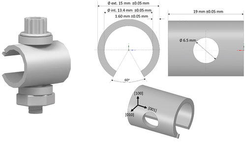
Table 1. Wt% composition of CMSX-4.
C-ring specimens were loaded to a maximum predicted stress of 700 MPa, according to the methodology outlined in Duarte et al. [Citation3]. During the deposit recoating method, the C-ring specimens are heated on a hot plate and subsequently sprayed with a dilute concentration of salt dissolved in deionised water. The high temperature of the specimen caused the water to evaporate almost immediately. The specimens were then weighed, and more salt would be applied until the required salt load on the surface was reached. The specimens were salted with NaCl and a flux of 1.2 µg/cm2/hr, which translates to a 0.18 ± 0.05 mg deposit recoat on each specimen.
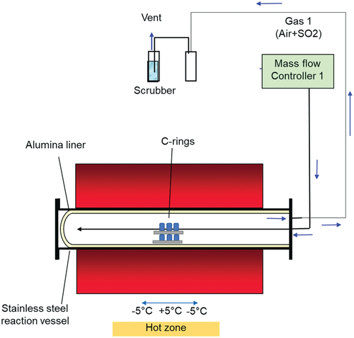
The C-rings were then exposed to a high-temperature atmosphere containing 50 ppm SO2 - air for 50 h in a horizontal furnace as shown in and, subsequently, inspected for cracking.
Figure 2. Schematic representation of the high temperature furnace used for the environmental exposure.
Characterisation
SEM/EDS characterisation
Once the 50-h exposure was completed, the samples were examined with SEM and EDS using a Tescan S8000. A focused ion beam assessment (FIB) was undertaken in selective areas. For the FIB assessment, a platinum strip was first deposited using a beam current of 150 pA, followed by milling a trench at a beam current of 10 nA, and ultimately the section was polished using a beam current of 1 nA.
Xrd
Given the thin scales that form at the moderate temperatures tested, high-resolution x-ray diffraction was required for accurate identification of the phases formed. The C-ring specimens were examined for phase identification using synchrotron X-ray diffraction (SXRD) at the Diamond Light Source synchrotron, Oxfordshire, UK.
Results
50 ppm SO2 - air atmosphere at 550°C
As shown in the optical images of , the specimen was exposed to a 50 ppm SO2–air environment for a 50-h period showed cracks initiating in regions where salt was deposited, however no cracks were observed in the C-ring exposed to air only. Shorter exposures were undertaken in 50 ppm SO2, and it was observed that cracks initiated in exposure times as low as 10 min, as shown in . After 10 min of exposure, a halo was observed surrounding the salt ridge, and this halo was rich in Na, Cl, S and O, potentially a mix of Na2SO4 and NaCl. The composition of this halo is a result of NaCl rapidly reacting with the SO2 containing environment to form Na2SO4 and release HCl and Cl2. Currently, no explanation exists for the observed spreading of salt post testing. It is possible that low melting point chloride eutectics were formed during the test, facilitating the lateral spread of the salt; however, this needs to be further understood. Nevertheless, the images in show that cracks initiate below the salt ridge and extend to the boundary of the diffused salt.
Figure 3. Optical image of salted C-ring exposed for 50 hours in (a) Air, and (b) 50 ppm SO2 – Air.
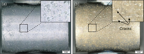
Figure 4. (a) Secondary electron (SE) image of the salt morphology before the exposure, (b) and (c) back scattered electron images of the top surface of the C-ring after 10 minutes of exposure.
The secondary electron (SE) images in , show significant differences in the scale morphology between the C-ring exposed to air only and the C-ring exposed to 50 ppm SO2 – air after 50 h of exposure. Apart from cracks being present in the C-ring exposed to the sulphur-containing environment, a porous scale is formed surrounding the salt, whereas no accelerated attack was observed in the air exposure.
Figure 5. SE image of salted C-ring exposed for 50 hours in (a) Air, and (b) 50 ppm SO2 - Air.
shows secondary electron images of the top surface after 50 h of exposure for the C-ring exposed to a 50 ppm SO2 - air environment. The halo surrounding the salt particles has developed a porous scale morphology, whereas regions further away have a denser morphology. Spallation was observed across the sample, but it was highly localised in regions where salt was applied. It is thought that the spallation may be a result of metal chlorides being present at the scale/alloy interface, which ultimately may reduce the adhesion between the scale and the alloy as reported by Elliott and Marsh [Citation4]. Ultimately, the porous scale and spallation sites that form lead to accelerated corrosion attack, as they are fast diffusion paths for the ingress of S, O and Cl.
Figure 6. SE images of the top surface of salted C-ring exposed for 50 hours in 50 ppm SO2.
Based on the EDS maps and the XRD analysis shown in , within the salt deposit, an external scale rich in NiO, NiSO4, CoO and CoSO4 was observed along with Na2SO4 salt. The inner scale was composed of a mix of chlorides, oxides and sulphides, involving Al, Cr, Ti and a subsurface region depleted of Ni and Co was observed. A region of approximately 3 µm of internal attack was observed, where both the γ and the γ’ phases are attacked. Overall, the corrosion attack was highly localised within the halo region surrounding each salt ridge.
Figure 7. EDS map of the top surface of salted C-ring exposed for 50 hours in 50 ppm SO2 - Air.
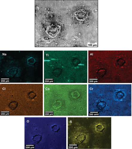
Figure 8. EDS map of cross-section through a NaCl salt deposit after 50 hours of exposure.
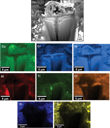
Figure 9. SXRD of specimen exposed in 50 ppm SO2 – air at 550°C after 50 hours of exposure.
It is thought that the reaction of SO2/SO3, O2 and H2O with NaCl leads to the release and inward diffusion of HCl and Cl2 through defects in the scale. As Cl2 and HCl reach the alloy/scale interface, the formation of metal chlorides occurs given their stability at low partial pressures of oxygen in that region. Within the halo (and away from the salt ridge), the formation and outward diffusion of NiCl2 and CoCl2 leave holes in the scale, as similarly reported in [Citation5], and this explains the porous morphology of the scale surrounding the salt ridge. Regions away from the halo formed more protective oxide and did not show concentrations of NiO, CoO or metal chloride formation at the alloy/scale interface. This highlights that the attack is highly localised to the NaCl salt depositions.
also show evidence of Cl, Al, Ti and Cr in regions where cracks are present, highlighting that AlCl3, CrCl3 and TiCl4 formed in these regions.
Air atmosphere at 550°C with NaCl salt
To further understand the effect of SO2/SO3, two C-rings had NaCl salt applied and were exposed in air at 550°C for 50 h. No cracks were observed to initiate after 50 h of exposure in air, and based on the EDS maps in , no significant outward transport of alloy elements was observed. However, after unloading and storing the specimens in a desiccator for several days, scale spallation was observed across the sample. The lateral transport of the salt, and the porous-scale microstructure observed in the sulphur containing environment is not present in the tests undertaken in air. Overall, limited corrosion attack was observed just below the salt deposits and negligible attacks occurred away from the salt deposits.
Figure 10. EDS map of the top surface of salted C-ring exposed in air for 50 hours.
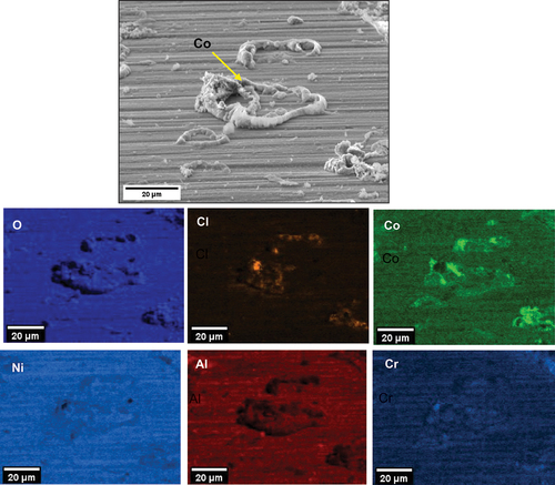
Figure 11. Top surface EDS map of C-ring exposed in air for 50 hours.
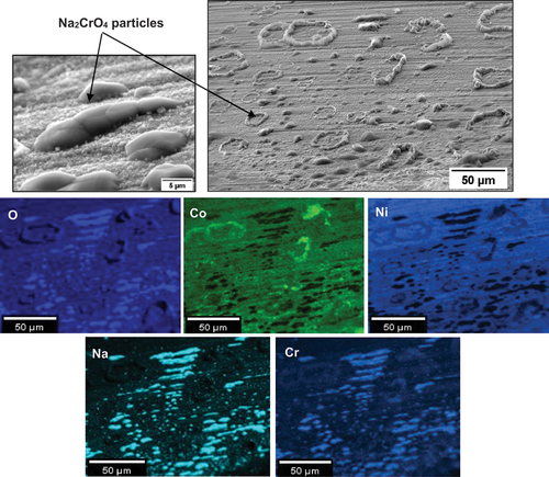
Based on the EDS map in , CoO and NiO formed within the salt deposit. Chlorine and sodium are relatively absent (which is further confirmed by the cross-sectional analysis). According to the high vapour pressure of NaCl at 550°C (2.17 × 10⁻⁷ atm based on FactSage 8.1 calculations), NaCl may have vaporised away, or alternatively, in some locations, it reacted with the scale.
shows a strong association of Co with the salt ridges. Also, nodule-type particles formed adjacent to the salt ridges, and according to the EDS map in , they were rich in Na, Cr and O, which suggests that the formation of Na2CrO4 may have occurred.
shows a cross section across one of the salt particles. One micron of internal attack and negligible amounts of chlorine are present at the alloy/scale interface. Overall, these EDS maps suggest that the accelerated oxidation of alloying elements is not as significant as when SO2/SO3 is present. Also, there is no evidence of AlCl3, CrCl3 and TiCl4 formation in air exposures, but they were present when the exposure was undertaken in 50 ppm SO2 - air. A summary of the corrosion products in the 50 ppm SO2 – containing environment and in air is shown in .
Figure 12. Cross-sectional EDS map of C-ring salted with NaCl and exposed in air for 50 hours.
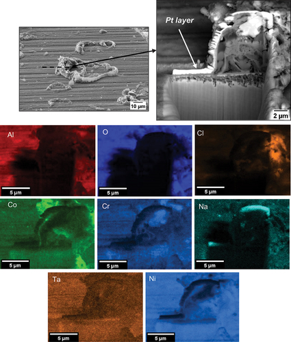
Figure 13. Schematic representation of the corrosion products formed in CMSX-4 when salted with NaCl and exposed to (a) 50 ppm SO2 – air and (b) air at 550°C.
Discussion
Corrosion mechanism
The results of this study have shown that NaCl significantly accelerates the rate of corrosion attack when the test is undertaken in a 50 ppm SO2 – air environment at 550°C. Cracks are observed to initiate at exposure times of only 10 min in the presence of 50 ppm SO2 – air, but no cracks initiate in air only after 50 h of exposure. Whilst the full extent of the mechanism is not yet understood, the following discussion represents the current latest theory as to why such cracking may arise.
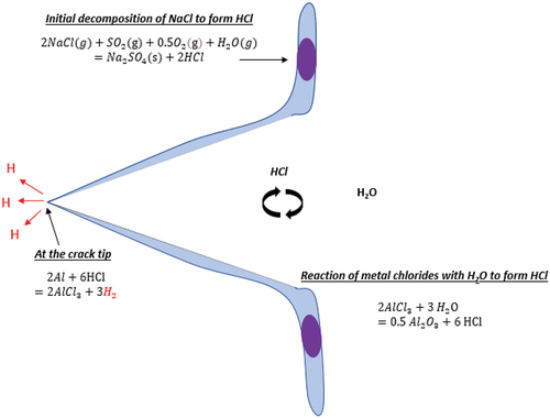
In the presence of SO2/SO3, the initial set of reactions starts with the sulphation of NaCl, as shown in the equation below, where the water vapour can be present in the humid atmosphere or as water crystallisation in NaCl salt, as reported by Chevrot [Citation6].
The HCl released diffuses through defects in the scale until it reaches the alloy/scale interface. At the alloy/scale interface, there is a low partial pressure of O2, and according to the predominance diagrams in , this low partial pressure of O2 favours the formation of metal chlorides and releases H2 gas in the process, according to the reactions shown in .
Table 2. FactSage 8.1 Gibbs free energy change calculations of metal chloride formation.
The metal chlorides formed have a high vapour pressure, and therefore favour outward diffusion. Upon exposure to higher partial pressures of oxygen within the scale they reoxidise. The reoxidation of metal chlorides releases Cl2 and HCl again according to , which diffuses inwards to repeat the process. This cyclic loop of metal chloride formation, vaporisation and reoxidation is known as active oxidation and is responsible for the accelerated corrosion rates of metals in chlorine-containing environments.
Table 3. FactSage 8.1 Gibbs free energy change of metal chloride oxidation at 550°C.
Based on , NiSO4, CoSO4 and Na2SO4 are present in the outer deposit, and AlCl3, CrCl3 and TiCl4 are present in the alloy/scale interface in the presence of SO2/SO3. On the other hand, in air, NiO and CoO are observed within the salt ridge, but no accelerated oxidation of Cr, Al and Ti is observed. The accelerated oxidation of Ni and Co within the deposit is suggested to form, as NiCl2 and CoCl2 formed as intermediate phases, which then reoxidise within the deposit.
The thermodynamic models to support these findings are presented in predominance diagrams and . They show that nickel and cobalt chloride require lower partial pressures of chlorine gas to form compared to other alloy elements (i.e. Al, Ti and Cr). The calculation assumes that the partial pressure of O2 at the scale/alloy interface is 10−20 atm, and although this is a modelled assumption, the trend is similar at other partial pressures of O2. As a result, it is suggested that the partial pressure of Cl2 at the alloy/scale interface in the air exposure is significantly reduced compared to that found in the sulphur-containing gas exposures. Consequently, these experimental observations and thermodynamic calculations suggest that the lower partial pressure of Cl2 present at the alloy/scale interface during air exposure is above that required to form NiCl2 and CoCl2 but below that required for chlorinated Al, Cr, Re and Ti. So, in air, the only elements involved in the outward cation transport due to the chlorination reaction are Ni and Co.
Table 4. Minimum P(Cl2) required to form metal chlorides at P(O2) of 10−20.
So, in few words, the interaction of the sulphur-containing environment with NaCl may be a more powerful way of releasing HCl and Cl2 (from a kinetics point of view), compared to the reactions of the alloy or the scale with NaCl to form Na2CrO4. Previous work done by Okoro et al. [Citation7] also supports these observations. The cited work suggests that the in-deposit sulphation of KCl to form K2SO4 can produce six orders of magnitude higher PCl2 at the scale/alloy interface than that resulting from reactions of KCl with Cr or Cr2O3 to form K2CrO4. Although Okoro did not provide an explanation as to why this low partial pressure of Cl2 occurs without the presence of the sulphur-containing environment, a possible reason may be due to the lower kinetics of reaction of KCl with Cr or Cr2O3 compared to the kinetics of reaction of KCl with SO2/SO3 and H2O. The interpretation by Okoro translates well to the observations in this work, where the sulphation of NaCl increases the partial pressure of Cl2 at the alloy/scale interface, which in turn promotes the chlorination of Al, Ti and Cr and may also accelerate the kinetics of chlorination. In air only, NaCl can react with Cr, O2 and H2O, to form Na2CrO4 and HCl according to the EDS map in and thermodynamic claculation shown in , but this reaction does not seem to lead to accelerated corrosion rates. Consequently, an accelerated oxidation of elements is observed in the presence of 50 ppm SO2 – air compared to only air.
Figure 14. Predominance diagrams for Ni, Co, Al, Ti and Cr (FactSage 8.1).
Table 5. Change in Gibbs free energy of reactions of NaCl with alloy elements.
There are different views regarding the effect of SO2 on the corrosion behaviour in the presence of alkali chloride deposits. As reported by Okoro et al. [Citation7] and Grabke et al. [Citation8], the concentration of SO2 plays an important role in accelerating the corrosion attack when KCl is condensed on a metallic surface compared to exposures in air only, but they only tested up to a concentration of 1000 ppm SO2.
On the other hand, it has also been reported by Paneru et al. [Citation9] that much higher concentrations of SO2 (15000 ppm) reduces corrosion rates compared to air exposures, as the alkali chlorides are preferentially sulphated in the deposit/gas interface, reducing the generation of HCl close to the alloy/scale interface. So, the SO2 concentration plays a role on the preferential sites of NaCl sulphation within the deposit, which, in turn, plays a role on the partial pressure of Cl2 at the scale/alloy interface, and therefore on corrosion rates. In summary, the accelerated corrosion rates observed in this study at low concentrations of SO2 (50 ppm) tested agree well with the results from the reported literature.
Crack initiation mechanism
Previous work undertaken on Hot Salt Stress Corrosion Cracking (HSSCC) of Ti-alloys has highlighted the importance of hydrogen embrittlement at temperatures of up to 500°C [Citation6], where HCl that is released in the reactions of NaCl with the oxide scale acts as a hydrogen carrier to the alloy/scale interface and can ultimately lead to hydrogen embrittlement. The mechanisms reported in HSSCC of Ti-alloys show similarities to the mechanism of cracking identified in this study. It is therefore postulated that hydrogen embrittlement may play a significant role in this study as well. The key part of the active oxidation mechanism caused by HCl and Cl2 is that, as metal chlorides form, hydrogen gas is released at the alloy/scale interface according to the equations in . Hydrogen gas can then dissociate into atomic hydrogen, which is absorbed in the alloy and causes embrittlement, as shown in . It is acknowledged that at these high temperatures, hydrogen is very mobile, and the assumption is that it must be injected rapidly into the alloy to cause embrittlement before it diffuses away [Citation6]. One way in which SO2 helps to support this mechanism, is by enabling the rapid release of Cl2 and HCl (which causes high partial pressures of Cl2 to be present at the alloy/scale interface). Ultimately, this may increase the chlorination kinetics, and the rate at which hydrogen gas would be released at the alloy/scale interface, according to the equations in .
Once cracks initiate, crack propagation would then occur following the same mechanism, where metal chloride formation at the crack tip, releases hydrogen gas, which then dissociates to form atomic hydrogen, and is absorbed in the substrate. Eventually, as the crack advances, the hydrostatic stress near the new crack front attracts hydrogen atoms, and further crack propagation occurs by hydrogen embrittlement.
Figure 15. Schematic representation of the hydrogen assisted crack propagation mechanism.
The work on HSSCC also suggests that the elements that are chlorinated play a significant role in whether cracks are initiated [Citation6]. For instance, they reported that pure Ti is immune to hot salt stress corrosion cracking, but when Al is added to the alloy composition, hot salt stress corrosion cracking occurs. The higher the concentration of Al in the alloy, the more significant the life reduction. The reason why the chlorination of Al plays an important role in crack initiation is not well understood. Nevertheless, it is thought to be due to the highly negative Gibbs free energy of AlCl3 formation compared to the chlorination of the other alloy elements, which enables high amounts of hydrogen to be formed at the alloy/scale interface. No consideration is given to the kinetics of AlCl3 formation, which is ultimately what would lead to high amounts of H being formed at the alloy/scale interface. If the formation of AlCl3 is so critical for hydrogen embrittlement to occur in Ti-alloys, a similar mechanism may also occur in nickel-based superalloys. The presence of SO2 facilitates the formation of AlCl3 from a thermodynamic point of view, thus enabling H embrittlement to occur. The key difference between the HSSCC mechanisms of Ti-alloy and Ni-based superalloys is a sulphur-containing environment is required in Ni-based superalloys to trigger this cracking. So, the chlorination of certain elements (i.e. Al) may be playing a more important role in the embrittlement than other elements (Ni and Co). Eventually, evidence of H embrittlement mechanisms (i.e. hydrogen enhanced localised plasticity, hydrogen-induced decohesion or hydride formation) is needed to further support this theory in the current work.
Previous studies have observed that single crystal nickel-based superalloys are susceptible to hydrogen embrittlement at room temperature. Dollar and Bernstein observed hydrogen to enhance strain localisation in the gamma matrix in CMSX-2, leading to a significant loss in ductility [Citation10]. In addition, Walston [Citation11] found that nickel-based superalloy PWA1480 is susceptible to hydrogen embrittlement when it is gas-phase charged at room temperature, and enhanced shear localisation was observed in the presence of hydrogen as well as a large increase in dislocation activity surrounding a crack in hydrogen charged samples compared to uncharged samples. Walston suggests that hydrogen enhanced localised plasticity (HELP) is the embrittlement mechanism responsible for crack initiation and that no other embrittlement process (i.e. hydrogen enhanced decohesion and hydride formation) was especially applicable in his study [Citation11]. In summary, although nickel-based superalloys are susceptible to hydrogen embrittlement at room temperature potentially through the HELP mechanism, its effect at higher temperatures (e.g. 450–550°C) is an area where more work should be focused, particularly in the presence of salt deposits and sulphur-containing environments.
Conclusions
This study has shown that the presence of stress, NaCl and SO2 lead to an accelerated corrosion attack in CMSX-4 and cracks initiate at exposure times as low as 10 min. The presence of a sulphur-containing environment creates high partial pressures of Cl2 at the alloy/scale interface, which favours the formation of AlCl3, TiCl4 and CrCl3, as well as potentially increasing the rate of chlorination reactions. Eventually, the active oxidation mechanism in the presence of a sulphur-containing environment may be a favourable way of releasing hydrogen gas at the alloy/scale interface and, therefore, injecting hydrogen rapidly into the alloy. Further work is ongoing to prove or disprove hydrogen as the embrittling species in CMSX-4 at 550°C.
Acknowledgments
We would like to thank Rolls-Royce plc. for supporting this work. This work has been funded by Innovate UK ATI under the MALIT program (Grant no. 113180)
Disclosure statement
No potential conflict of interest was reported by the authors.
Additional information
Funding
References
- Birks N, Meier GH, Petit FS. Hot corrosion. In Introduction to the high temperature oxidation of metals, 2nd. 2006 ; New York: Cambridge University Press; p. 205. https://books.google.co.uk/books/about/Introduction_to_the_High_Temperature_Oxi.html?id=5Q2iBV35yogC&redir_esc=y
- Gheno T, Zahiri Azar M, Heuer AH, et al. Reaction morphologies developed by nickel aluminides in type II hot corrosion conditions: the effect of chromium. Corros Sci. 2015;101:32–46.
- Martinez FD, Morar NI, Kothari M, et al. Investigation in to the effect of salt chemistry and SO2 on the crack initiation of CMSX-4 in static loading conditions. Superalloys. 2020;753–762. https://link.springer.com/chapter/10.1007/978-3-030-51834-9_73
- Elliott P, Marsh G. The oxidation of incoloy 800 in moist air containing HCl(g) at 800°C. Corros Sci. 1984;24(5):397–409.
- Peng J, Huang T, Song P, et al. Effect of platinum and pre-oxidation on the hot corrosion behavior of aluminide coating with NaCl at 1050 °C. Mater Res Express. 2020;7(11):116402. DOI:10.1088/2053-1591/abc4b2
- Chevrot T. Pressure effects on the hot-salt stress-corrosion cracking of titanium alloys. Cranfield University; 1994. https://dspace.lib.cranfield.ac.uk/handle/1826/7745
- Okoro SC, Kiamehr S, Montgomery M, et al. Effect of flue gas composition on deposit induced high temperature corrosion under laboratory conditions mimicking biomass firing. Part II: exposures in SO2 containing atmospheres. Mater Corros. 2017;68(5):515–528.
- Grabke HJ, Reese E, Spiegel M. The effects of chlorides, hydrogen chloride, and sulfur dioxide in the oxidation of steels below deposits. Corros Sci. 1995;37(7):1023–1043.
- Paneru M, Stein-Brzozowska G, Rg Maier J, et al. Corrosion mechanism of alloy 310 austenitic steel beneath NaCl deposit under varying so 2 concentrations in an oxy-fuel combustion atmosphere. 2013 [cited 2019 Oct 29]; Available from: https://pubs.acs.org/sharingguidelines
- Dollar M, Bernstein IM. The effect of hydrogen on deformation substructure, flow and fracture in a nickel-base single crystal superalloy. Acta Metall. 1988;36(8):2369–2376.
- Walston WS. The effect of hydrogen and microstructure on the deformation and fracture behavior of a single crystal nickel-base superalloy. Pittsburgh, Pennsylvania; 1990.