
ABSTRACT
Studying chemical reactions in an environment that closely mimics the system’s natural operating conditions can offer crucial insights into dynamic oxidation processes. Transmission Electron Microscopes (TEMs) and X-ray Nanoprobes allow the use of imaging and spectroscopy to access nanoscale chemical and structural information about these processes. However, the controlled operating conditions and constraints make the design and implementation of in situ sample environments challenging. Here, we outline the setup of an in situ liquid sample environment for the Hard X-ray Nanoprobe beamline (I14) at Diamond Light Source. The liquid environment allows for the imaging and spectroscopic analysis of samples exposed to liquid flow, with heating up to 80℃. The capability is demonstrated with an example experiment studying iron corrosion. The design of the sample cell offers the prospect of combining X-ray and electron microscopy for the in situ multi-length scale imaging and spectroscopy of samples in liquid.
Introduction
Studying dynamic oxidation reactions in conditions that are close to a system’s natural environment can reveal crucial information for the study of chemical processes, for example when studying energy materials [Citation1] or corrosion mechanisms [Citation2]. Scanning X-ray nanoprobe imaging and spectroscopy techniques are powerful tools for the study of such chemical reactions and processes, especially when combined with in situ reaction environments, and are complementary to electron microscopy studies [Citation3–8]. Implementing in situ environments on nanoprobe beamlines is, however, challenging due to the demands imposed by restricted operating space and the need for high thermal and vibrational stability. These challenges and restrictions are in part shared with in situ electron microscopy sample environments, thus one approach to developing nanoprobe sample environments is to adapt existing TEM developments for use on beamlines.
At Diamond Light Source, the United Kingdom synchrotron facility, the hard X-ray nanoprobe (beamline I14) offers a 50 nm focused X-ray beam [Citation9]. As a sample is scanned through the focused beam, spatially resolved element composition, phase and speciation changes can be studied using a combination of x-ray fluorescence (XRF) [Citation10], differential phase contrast imaging (DPC), X-ray absorption near-edge spectroscopy (XANES) [Citation11] and X-ray diffraction (XRD) [Citation12,Citation13]. In previous work [Citation14], we have reported the development of an in situ gas setup to be used across the nanoprobe beamline and the TEM facilities at the Diamond Light Source electron Physical Science Imaging Centre (ePSIC) for multi-length scale correlative spectroscopic imaging studies. The cell is a DENSsolutions Microelectromechanical systems (MEMS) based gas-heating environment supporting a temperature ramp up to 1000℃.
Here, we present the development of this capability at the I14 beamline to provide a liquid sample environment capable of heating up to 80℃. We demonstrate the use of the liquid setup for studying in situ iron corrosion. Studying corrosion dynamics of iron-based materials is of significance in a wide range of industries and this approach allowed visualising the process at nanoscale resolution in real time, through mapping of the Fe-Ka fluorescence signal. The design of the cell also allows for the application of additional nanoprobe techniques such as XANES and XRD, while the architecture of the cell allows the prospect of correlative studies at other beamlines or electron microscopes.
Materials and methods
The in situ cell at the beamline
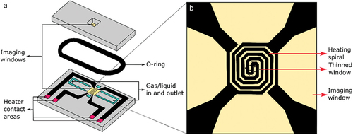
For the liquid setup on the beamline, the same sample mount and commercially available DENS solutions reaction chips are used as for the gas setup () [Citation14]. The climate reaction environment (product number P.J.GH.SS2) is mainly used at I14, but any DENS solution reaction chips that are compatible with a JEOL TEM holder can be used on request. The climate reaction environment consists of two chips, each with an 800 × 800 µm silicon nitride window of 400 nm thickness (). The chips are designed for gas flow and heating. Alternative chips with a smaller window area are available for liquid flow; these reduce the amount of window bulging, and hence the thickness of the liquid layer, important for maintaining resolution while imaging in the TEM. The greater penetrating power of X-rays compared to electrons mean that the liquid thickness is not as critical and we have used the gas cell chips for liquid flow to maximise the viewing area available. Liquid is passed through the cell, across the imaging windows, by use of the inlet and outlet holes. These holes are attached to silica tubing of 180 µm inner diameter. The inlet silica tubing is in turn connected to PEEK tubing (IDEX) through a valve which is attached to a glass syringe on a syringe pump. As such, liquid can flow through the chip, with a variable flow rate, ideally 5 µL/min or less to avoid breaking the windows of the chip by applying too much pressure. A molybdenum heating spiral is patterned on the window of the bottom chip (), to allow for heating of the sample up to 80℃ (1000℃ when using it in a gas environment). This heating element can be coupled to a temperature controller through custom-made needle-like heating contacts that connect with the heating contact areas (). The heater spiral covers an area of 500 µm x 500 µm, although the sample can cover a larger area that crosses the boundary of the window up to a maximum of 2 mm x 6 mm. In between the spirals of the heating element there are several thinned circular areas of 20 nm silicon nitride thickness and 6 µm diameter (), to reduce scattering of electrons when used in the TEM and thus increase imaging resolution. As x-rays have a larger penetration depth, imaging on the I14 beamline can be done anywhere on the window apart from directly on top of the heating element. The sample is placed on the window of the bottom chip, after which both chips are combined and sealed by a rubber o-ring (Viton) ().
Figure 1. Schematic of the DENSsolutions in situ chip. (a) The DENSsolutions in situ chip (P.J.GH.SS.2, climate chip for JEOL holder). It can be used for correlative imaging in gas environments across the I14 beamline and the ePSIC E01 TEM, or for liquid experiments on the I14 beamline. The silicon nitride imaging windows are indicated in yellow. A liquid or gas can be inserted into the chip through the inlet and outlet. The temperature controller can be connected through the heater contact areas to heat the sample and sample environment. The o-ring is used to seal the top and bottom chip. (b) Magnified view of the imaging window, showing the heater spiral and the thinned 20 nm imaging areas. TEM imaging is limited to these areas, while X-ray imaging on the beamline can be done anywhere on the window.
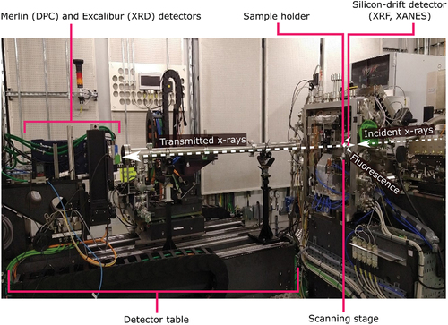
Once assembled, the sample holder is mounted on the beamline scanning stages using a holder on a kinematic mount to allow for ease of setup and alignment. The sample is then scanned through the focused X-ray beam and X-ray fluorescence (XRF) data is collected by a four-element silicon-drift detector in the backscatter geometry (RaySpec, UK). Additional differential phase contrast (DPC) or X-ray diffraction (XRD) data can be collected downstream in transmission mode using the Merlin Quad detector (Quantum Detectors, UK) or Excalibur detector [Citation15] mounted on the detector table. By scanning the X-ray energy (accessible energies 5–20 keV) and collecting XRF maps at multiple energies through an elemental absorption edge, X-ray absorption near edge structure (XANES) maps can be extracted. The beamline experimental hutch is shown in . More information on the beamline setup can be found in [Citation9].
Figure 2. The hard x-ray nanoprobe end station. Photograph showing the I14 beamline setup inside the experimental hutch. The light path of the x-rays is indicated, along with the detectors, sample holder position, scanning stage and the detector table.
Iron corrosion
A thin layer of iron film (400 nm) was deposited on the silicon nitride reaction chips (top chip of (a)) via e-beam evaporation. The reaction chips were treated in UV-ozone for 15 minutes prior to deposition, to improve the adherence of the metal layer to the ceramic chip. A Cu wire physical mask (100 µm diameter) was used to mask a portion of the reaction chip to create an edge of the deposited metal on the viewing window. This allowed us to easily distinguish between the metal film region and the substrate.
A 0.1 M NaCl solution at pH 6.8 (pH adjusted using NaHCO3) was passed through the assembled liquid cell at a rate of 100 µL/min and the cell was heated to 80°C, at a ramp of 10°C/min before the start of data collection. The high flow rate used here was selected to endure a fresh flow of solution over the iron film during the experiment. The flow rate requires further optimisation but is a balance between providing an adequate supply of ions in the solution to the reaction site, removing any ionising beam products from the reaction site, and in this experiment not removing the corrosion products from the system to enable them to be studied.
The sample was mapped consecutively, with XRF data measured over a 30 µm × 30 µm area using a 250 nm step size and a 0.015 s exposure time at an incident beam energy of 7.308 keV, so that a full scan took 3.6 minutes. In between XRF data collections XANES maps were collected at the Fe-Kα edge on a smaller subsection of the area. These data are not reported here, but as will be shown below the extra beam exposure in that region is important for understanding the results presented.
Results and discussion
The edge of the iron film can be clearly seen in the XRF images, . After 30 minutes of immersion, the sample shows no obvious degradation, with a clear edge to the iron film as seen in the Fe-Kα XRF maps. After 2 hours of immersion, the intensity of the Fe-Kα signal is reduced in a small region of the film as the film has corroded and small regions of corrosion product have formed in the surrounding regions (high intensity white spots). It is noted that the small area of corrosion corresponds to the region of the sample that was exposed to a higher beam dose due to XANES mapping (the area of XANES mapping is indicated by the rectangle of white dashed lines in the 3 h panel in ). The high dose of X-rays accelerates the corrosion of the iron film in that localised region likely due to radicals formed upon water radiolysis, which can be highly corrosive [Citation16]. These X-ray beam – sample interaction effects are complex but must be considered carefully for liquid studies.
Figure 3. Corrosion in iron metal. XRF images, Fe-Ka signal, of iron metal film exposed to brine solution, imaged on the I14 beamline using the in situ liquid setup. XANES measurements are performed in between the XRF measurements, in the area that is outlined in the 3h panel by a rectangle of white dashed lines, thus this area has been exposed to a higher X-ray dose. This demonstrates that the corrosion reaction is accelerated by the effects of the X-rays.
These XRF images provide an insight into the ability to study corrosion reactions in situ at nanoscale resolution using a nanoprobe beamline. Further analysis of this sample, including the speciation of the corrosion products that are formed, can be done through analysis of the measured XANES spectra. As such, this method offers a promising route for the investigation of corrosion reactions.
The in situ liquid cell is a valuable addition to the gas/heating sample environment capabilities of the X-ray nanoprobe and is available to users at I14 for use in a wide variety of in situ applications, from corrosion through to crystallisaton. Through the approach of adapting and utilising existing TEM sample environment technology, we aim to maintain the prospect of expanding to correlative X-ray/TEM studies, which requires corresponding environments to be available across instruments and techniques. Care must be given to the development of these setups as changes in the environment can alter the system behaviour. Issues such as the effects of X-ray or electron beam on the reaction as well as the cell dimensions and confinement effects on ion availability and diffusion must be considered in order to fully characterise a sample system and understand the influence of the measurement environment on its behaviour.
Acknowledgments
SA, SC, MS, DC, RL, MD and AO acknowledge funding and technical support from bp through the bp International Centre for Advanced Materials (bp-ICAM) and EPSRC through the prosperity partnership (EP/G036850/1). AO is appreciative of Petroleum Technology Development Fund (PTDF) for PhD funding. SA would like to thank Trinity-Henry Barlow Scholarship Trust for partial PhD funding support. DC is appreciative of funding from the EPSRC (EP/L01680×/1) through the Materials for Demanding Environments (M4DE) Centre for Doctoral Training (CDT). The authors acknowledge Diamond Light Source for access to Beamline I14 under proposal mg28835. Mark Hooper and David Mahoney are thanked for the design and implementation of the cell mounting on I14.
Disclosure statement
No potential conflict of interest was reported by the authors.
Additional information
Funding
References
- He X, Larson JM, Bechtel HA. In situ infrared nanospectroscopy of the local processes at the Li/polymer electrolyte interface. Nat Commun. 2022 Dec;13(1):1398. doi:10.1038/s41467-022-29103-z.
- Luo L. Atomic origins of water-vapour-promoted alloy oxidation. Nat Mater. 2018 Jun;17(6):514–518. doi:10.1038/s41563-018-0078-5.
- Staniuk M. Puzzling mechanism behind a simple synthesis of cobalt and cobalt oxide nanoparticles: in situ synchrotron X-ray absorption and diffraction studies. Chem Mater. 2014 Mar;26(6):2086–2094. doi:10.1021/cm500090r.
- Li H, Meng R, Guo Y, et al. Reversible electrochemical oxidation of sulfur in ionic liquid for high-voltage Al−S batteries. Nat Commun. 2021 Dec;12(1). DOI:10.1038/s41467-021-26056-7.
- Liu X, Yang W, Liu Z. Recent progress on synchrotron-based in-situ soft X-ray spectroscopy for energy materials. Adv Mater. 2014 Dec;26(46):7710–7729.
- Yao Y, Hu Y, Scott RWJ. Watching iron nanoparticles rust: an in situ X-ray absorption spectroscopic study. J Phys Chem C. 2014 Sep;118(38):22317–22324. doi:10.1021/jp506281d.
- Song Z, Xie Z-H. A literature review of in situ transmission electron microscopy technique in corrosion studies. Micron. 2018 Sep;112:69–83.
- Fan Z. In Situ transmission electron microscopy for energy materials and devices. Adv Mater. 2019 Aug;31(33):1900608. doi:10.1002/adma.201900608.
- Quinn PD. The hard X-ray nanoprobe beamline at diamond light source. J Synchrotron Radiat. 2021 May;28(3):1006–1013. doi:10.1107/S1600577521002502.
- Negahdar L. Elucidating the significance of copper and nitrate speciation in Cu-SSZ-13 for N2O formation during NH3-SCR. ACS Catal. 2021 Nov;11(21):13091–13101. doi:10.1021/acscatal.1c03174.
- Bolitho EM. Single-cell chemistry of photoactivatable platinum anticancer complexes. J Am Chem Soc. 2021 Dec;143(48):20224–20240. doi:10.1021/jacs.1c08630.
- Macpherson S. Local nanoscale phase impurities are degradation sites in halide perovskites. Nature. 2022 Jul;607(7918):294–300. doi:10.1038/s41586-022-04872-1.
- Doherty TAS. ‘Stabilized tilted-octahedra halide perovskites inhibit local formation of performance-limiting phases’. [Online]. Available: https://www.science.org
- Parker JE. A cell design for correlative hard X-ray nanoprobe and electron microscopy studies of catalysts under in situ conditions. J Synchrotron Radiat. 2022 Mar;29(2):431–438. doi:10.1107/S1600577521013576.
- Marchal J. EXCALIBUR: a small-pixel photon counting area detector for coherent X-ray diffraction - Front-end design, fabrication and characterisation. J Phys. 2013;425(6):062003. PART 6. doi: 10.1088/1742-6596/425/6/062003.
- Mayanovic RA, Anderson AJ, Dharmagunawardhane HAN. Monitoring synchrotron X-ray-induced radiolysis effects on metal (Fe, W) ions in high-temperature aqueous fluids. J Synchrotron Radiat. 2012 Sep;19(5):797–805. doi:10.1107/S0909049512029093.