Abstract
Inertial Navigation System (INS) and Global Navigation Satellite System (GNSS) integration requires accurate modelling of both INS deterministic and stochastic errors. The Allan Variance (AV) analysis on INS static data is one method of determining INS stochastic errors. However, it is known that INS errors can vary depending on a vehicle’s motion and environment, and application of AV results from static data in kinematic operations typically results in an over-confident estimation of stochastic. In order to overcome this limitation, this paper proposes the use of Dynamic Allan Variance (DAV). The paper compares the resulting performance of the INS/GNSS integrated system by varying the stochastic coefficients obtained from the AV and DAV. The results show that the performance improved when utilizing the stochastic coefficients obtained from the DAV, applied on a kinematic dataset compared to the AV, applied on a static laboratory dataset.
1. Introduction
Inertial sensors play a critical role in most of today’s navigation systems, particularly for improving the availability of positioning. It is a high rate sensor which contains three accelerometers and gyroscopes to measure accelerations and turning rates respectively, relative to its body frame. To obtain a meaningful navigation solution, measured accelerations are translated from the inertial sensor’s body frame into a defined reference frame, typically being local-level or navigation reference frame. This system is termed as an Inertial Navigation System (INS). The INS keeps track of its orientation by integrating measured turning rates, and of its velocity and position by integrating accelerations. The performance of an INS is strictly limited by the errors inherent in the inertial sensor. This is the main drawback of INS, where integration of noisy measurements will cause errors to propagate with time, also known as position and attitude drifts. Therefore, INS is commonly integrated with other positioning methods such as Global Navigation Satellite System (GNSS) in order to bound error propagation Citation(1). The Extended Kalman Filter (EKF) is one of the most common methods of such integration. Implementation of such integrated system requires careful and accurate error modelling.
INS errors can be categorized into two groups; deterministic and stochastic errors. Bias, scale factor and non-linearity are the major contributors to deterministic errors, which can typically be removed by lab calibration procedures. Stochastic errors however, are not directly measureable. Therefore, it is important to model stochastic errors and include the models in the integration algorithm to effectively remove these errors. In trying to determine stochastic errors, several techniques have been developed. The traditional method of using a single Root-Mean-Square (RMS) value with associated correlation time proved to be inadequate to accurately characterize sensors performance. Therefore, alternative techniques using frequency-domain and time-domain approaches were introduced in trying to determine different types of INS stochastic errors Citation(2).
Power Spectral Density (PSD) is an example of a frequency-domain approach. PSD can be calculated in a number of different ways but it is generally defined as the Fourier transform of its autocorrelation function. It is a powerful tool for analysing and modelling stochastic processes but difficult for non-system analyst to comprehend Citation(2). On the other hand, correlation methods are based on the time-domain approach. An example of correlation method is the autocorrelation function, which measures the dependence of the process value at one time with its value at other times. Another example of correlation method is the autoregressive moving average process. The shortcoming of the correlation methods is that they require extensive data collection. Furthermore, correlation approaches are also model-sensitive and not well suited when dealing with odd power law processes, higher order processes or a wide dynamic range Citation(2).
The Allan Variance (AV) is another example of a time-domain approach. It was developed in the mid 1960s to characterize phase and frequency of precision clocks and oscillators Citation(2). Recent studies Citation(3–Citation8) have applied this technique to identify and model stochastic errors in INS due to its simplicity and efficiency in comparison to PSD and autocorrelation methods. Using AV allows identification of five stochastic errors that are inherent in an INS, namely quantization noise, angle/velocity random walk, bias instability, rate random walk and rate ramp. The identified errors are then analysed to extract their coefficients, which are then applied in the INS/GNSS integration algorithm. In these studies, the AV is applied on INS static data, collected in a controlled laboratory environment. However, Ref. Citation(9) has shown that INS errors are a function of motion and other environmental effects such as vibration. Thus, it is important that these effects are accounted for to optimize the integrated system. Due to the impacts of motion and environmental conditions on INS measurements, AV is not suitable to identify INS errors as AV assumes static conditions. Here, the term static is defined as the measurement noise signals being time invariant Citation(10). To overcome this limitation, this paper has applied the dynamic Allan variance (DAV) on the INS measurement errors for kinematic cases. The DAV is a modified version of the AV, allowing for a time-varying AV analysis Citation(11–Citation13). The DAV has been adapted mainly for clock characterization testing, particularly in GNSS satellites. For example, it was used for the characterization of the clocks on-board the first group of experimental Galileo satellites. The U.S. Naval Research Laboratory is also using DAV to monitor and test GPS clocks Citation(11).
This paper presents the results of INS stochastic error detection during kinematic tests and the implications for INS/GNSS integrated system performance. First, the methodologies of AV and DAV are presented. This is followed by a brief description of the static and kinematic experimental set-ups, including the sensors used. The results section discusses the extracted error parameters using AV and DAV and their impacts on INS/GNSS integrated system performance. Finally, the paper concludes and lays out further recommendations.
2 Allan variance and dynamic Allan variance
2.1 Allan variance
The AV of a time series of data is a characterization of the noise and other processes in the data, as a function of averaging time. Prior to calculating AV, pre-processing or analysing a subset of data can be useful and at times, recommended. This is to ensure the results of the noise characterization are not affected or masked by other noise sources. However, it is important to note that pre-processing raw data may also prevent the resolution of certain noise processes or underestimate the noise coefficient values. Pre-processing is needed, for example, when sudden change of velocity or angle bias is present. This region should be excluded from the analysis as it might affect the correctness of the analysis. Also, signal bias should be removed before integrating signals if the angle or velocity random walk is not apparent in the result of the analysis due to quantization noise dominating in the high frequency region Citation(2).
AV can be calculated from a finite number of data samples that are stationary in time. It can be defined either in terms of the instantaneous output rate or the angle/velocity integration output. These are mathematically identical, providing the option to use output rate or angle/velocity data as an input in the analysis Citation(7). Calculation of AV is straightforward as shown below. In the case where instantaneous output rate is the input to AV, assume a dataset consists of N samples. These are separated into clusters based on the sampling time , where
is the fixed time interval between two successive data points. Next, the data in each cluster is averaged and successive clusters of same lengths (
) are differenced. AV can then be calculated by squaring, then summing the differences between clusters, and finally dividing by a rescaling factor. These steps are repeated using different sampling times
by varying
. A more detailed discussion on AV calculation can be found in Ref. Citation(8). The formulations of AV are listed as follows. First, the average of the rate output
in k-th cluster is calculated using
(1)
Then, the subsequent cluster average is given by(2)
The differences between pairs of clusters are given by(3)
Finally, the AV of length is calculated using
(4)
Alternatively, Equation (4) can be reconstructed as Equation (5) where θ is a product of integration of the rate output .
(5)
2.2 Dynamic Allan variance
The DAV is an extension of the AV, where it is able to reveal the time varying properties of a set of signals. The basic concept of DAV is based on the repetitions of the AV evaluation at different epochs, which can then be visualized in a 3-Dimensional (3D) graph Citation(11). This would reveal any non-static noise behaviour over time Citation(10). The DAV procedure can be summarized as follows Citation(11):
Set the analysis epoch
Set the desired analysis window
Evaluate the AV
Set another analysis epoch and repeat from i. The new epoch can be set to make the data within its corresponding new analysis window overlaps with the previous epoch and analysis window.
Further details of DAV can be found in Ref. Citation(11). The formulation for the discrete time DAV is as follows:(6)
where is the the analysis epoch.
2.3 INS stochastic noise terms
The five main error sources of INS that can be detected using AV are as follows.
2.3.1. Quantization noise
Quantization noise is a result of the signal encoding process from analogue to digital form. This process is limited by the system’s bit resolution and results in a small difference between the actual amplitude and digital readout Citation(14). In AV log-log graph, it is represented by a slope of −1 and the coefficient value can be extracted using the slope line at . The units for quantization noise are
and
(radians).
2.3.2 Angle/velocity random walk (A/VRW)
A/VRW describes the deviation that occurs when signals are integrated. The origin of the noise comes from the fact that signals from INS are perturbed by white noise, which is caused by thermo mechanical noise fluctuating at rates greater than the actual samples. Integrating the white noise will consequently result in a zero mean A/VRW. Identifying and modelling A/VRW is essential as it can be a major source of error in INS. It is represented by a line with a slope of −0.5 and the coefficient value can be read at the slope line . The units for A/VRW are
for velocity and
for angle Citation(7, Citation15).
2.3.3 Bias instability
Bias instability describes how the bias wanders over time as a result of random electronic flickering. It is usually observed at low frequencies and is associated with a correlation time. It is represented by a line with a slope of 0 and its coefficient value is at the lowest point of the AV curve. The units for this error are and
Citation(7, Citation16).
2.3.4 Rate random walk (RRW)
RRW is of uncertain origin. It is possibly a limiting case of an exponentially correlated noise with a long correlation time. RRW is represented by a line with a slope of + 0.5 and the coefficient value can be extracted at . The units are
and
Citation(7).
2.3.5 Rate ramp
Rate ramp reveals any deterministic error that is present in the dataset. It is represented by a line with a slope of + 1 and the coefficient value at Citation(7).
3 Experiment setup
This section details the experiment setups for the static and kinematic tests. In both tests, a Xsens Mti-G unit was used. The Xsens Mti-G is a MEMS based INS/GPS navigation device consisting of tri-axial accelerometers, gyroscopes and magnetometers, a GPS receiver and an on-board processing unit. Its GPS receiver can make use of up to 50 channels of the GPS C/A code on the L1 frequency and track at up to 4 Hz, while its on-board processing unit is able to fuse the INS and GPS data in real time.
3.1 Static laboratory test
For the static test, two hours of stationary data was collected under controlled environmental conditions. First, the room temperature was kept constant throughout the whole test as it plays a critical role in the INS performance Citation(17). Second, the test was conducted at night to avoid any possibility of unwanted vibrations.
3.2 Kinematic test
The kinematic test was conducted in Nottingham, UK as part of a multi sensor data collection campaign conducted jointly by the FIG working group 5.5 and IAG working group 4.1.1 Citation(18). For the test used in this paper, road sections of the A52 Clifton Blvd., near the University of Nottingham campus were used. In total, the test lasted for more than two hours but only half an hour of data was used for this paper. Three main sensors were used in this test: a navigational grade INS (Honeywell CIMU), a geodetic grade GNSS receiver (Leica GS10) along with the MEMS based INS (Xsens Mti-G). The navigational grade INS, integrated with dual-frequency GNSS solution was used as the reference data, because of its high accuracy navigation solution. The CIMU/GNSS navigation solution (position, velocity and attitude) is then used to derive body acceleration and turning rates which are used to compute the Xsens Mti-G measurement residuals.
4 Results and discussion
The first subsection presents the extracted INS stochastic error coefficients using both AV and DAV. The second subsection then compares the performance of the INS/GNSS, using the extracted coefficients from AV and DAV.
4.1 INS stochastic errors
4.1.1 Allan variance
The AV (Equation (5)) was applied on the inertial sensor output to determine the coefficients of various stochastic processes. The error coefficients are extracted by analysing the log-log graph (Allan deviation vs. time sampling
, where the underlying stochastic processes can be identified by their slopes at different
, as preciously discussed. We refer to Table to identify the errors with their associated slopes on a log-log graph.
Table 1. INS stochastic noise terms.
Figures show the resulting vs.
. In these graphs, it is clear that the most dominant error is the A/VRW. For accelerations, the lines with –0.5 slope range from approximately
0.05 to 2 while turning rates range from
0.02 to 10. Bias instability can be seen in the
300–550 and 130–530 regions for acceleration and turning rates respectively. Table lists the extracted A/VRW coefficients while Table lists the bias instabilities coefficients (
and
) and their corresponding time correlations (
).
Figure 1 Allan deviation plot of static accelerations.
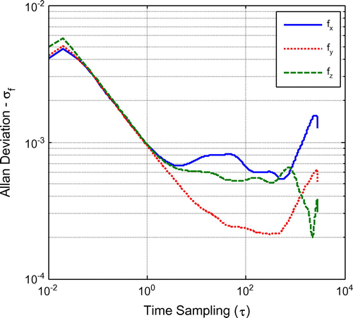
Figure 2 Allan deviation plot of static turning rates.
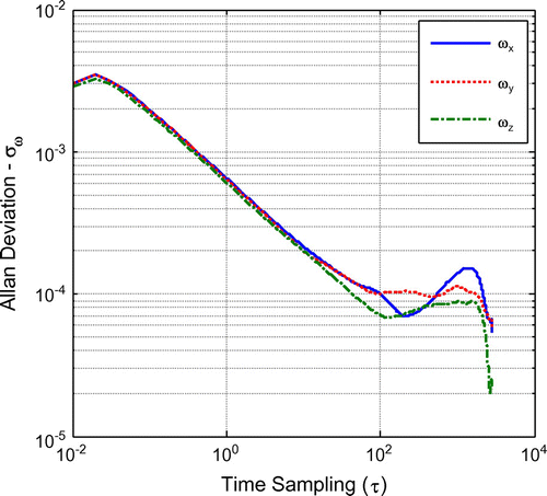
Table 2. INS A/VRW coefficients.
Table 3. INS acceleration and turning rate bias instability coefficients.
4.1.2 Dynamic Allan variance
Unlike the AV, the DAV (Equation (6)) allows for the calculation of multiple Allan Deviations from a single dataset, by varying the analysis window (Nw) and the desired step interval (). In this analysis, Nw is set to 60 s and
is set to execute every 10 s. It is noted that due to the short Nw window, only quantization and A/VRW are expected to be visible in the DAV graph, as other processes such as bias instability require longer windows. For example, in Table , the acceleration bias instability can be observed only in the
of 300–550 region. The DAV is represented in a 3D log-log graph, where in addition to
versus
, the application time of the DAV is plotted.
The DAV is first applied to the static data to check for consistency with AV based results. It is expected that the DAV based stochastic coefficients are similar to the ones obtained from AV as the same static dataset is used. Figure shows the resulting DAV for acceleration X while Table lists the averaged (taken from five samples) A/VRW for all axes. In Figure , it is observed that there are only minimal variations between Allan deviations at different times. This is expected as the amplitude of the white noise, which results in A/VRW when integrated, remains constant throughout the static dataset. Hence, the resulting A/VRWs coefficients are also similar. In Table , it is observed that the extracted A/VRW coefficients are very close to the ones obtained using AV, listed in Table with differences of only 2.43E-05, validating the DAV analysis.
Figure 3 DAV plot of kinematic acceleration X.
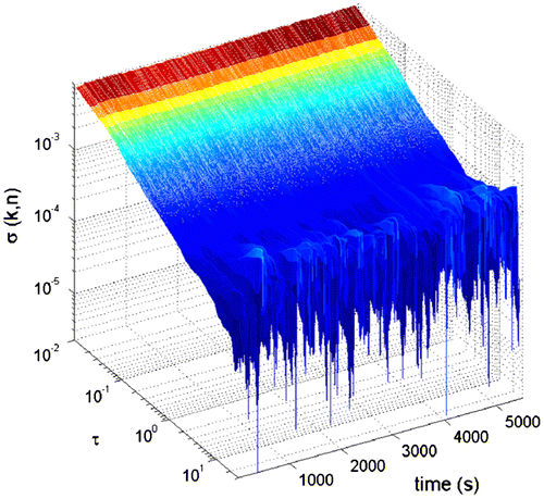
Table 4. A/VRW coefficients from DAV static.
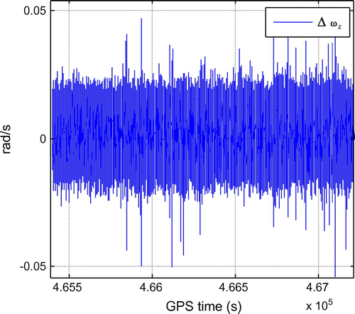
The DAV is also applied on the kinematic data residuals. The residuals () are obtained by subtracting the accelerations and turning rates derived from CIMU/GNSS from the ones measured by the Xsens Mti-G. The CIMU/GNSS accelerations and turning rates are derived from the velocity and attitude & heading reference system, differentiated with respect to time. These values are then rotated from the navigational frame to the body frame using its attitude & heading information. Figures show the residuals between acceleration and turning rates derived from CIMU/GNSS and Xsens Mti-G. In these two graphs, it is observed that the acceleration residuals vary significantly more than the turning rate residuals. Furthermore, the regions with higher variations are associated with the kinematic portion of the data, indicating the presence of motion dependent errors. It is also worth noting that the measured accelerations during the kinematic test contain higher noise amplitudes due to vibrations, compared to the measured accelerations in the laboratory test.
Figure 4 Δ Acceleration X: CIMU/GNSS vs. MEMS Xsens Mti-G.
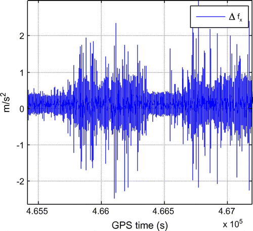
Figure 5 Δ Turning rate Z: CIMU/GNSS vs. MEMS Xsens Mti-G.
Figures show the DAV results for acceleration X and turning rate Z during the kinematic test. In Figure , it is observed that the varies significantly, reflecting the effects of motion dependent errors, also seen in Figure . Furthermore, when observing the lower peaks of the assembled
, associated with the static part of the kinematic test, the
is higher than the ones in Figure , reflecting the vibration effect. On the other hand, only minimal variations of σ are observed in Figure . This suggests that unlike measured accelerations, the turning rates are not affected by environmental changes. In fact, the calculated
values are almost identical to the ones in Figure . Again, this suggest sthat the measured turning rates are not affected by vehicle motions and vibrations.
Figure 6 DAV plot of kinematic acceleration X.
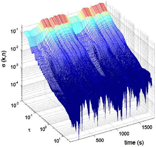
Figure 7 DAV plot of kinematic turning rate Z.
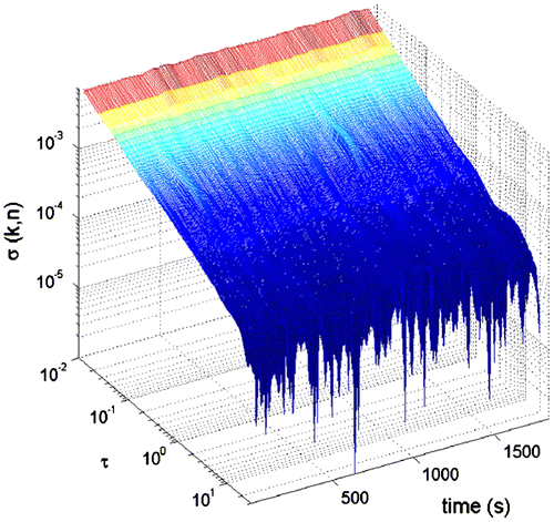
Table lists the A/VRW coefficients from the kinematic test. The minimum column lists the averaged A/VRW obtained from the lower peaks while the maximum lists the averaged A/VRW obtained from the upper peaks of the calculated DAV. It is clear from these results that the values for maximum are higher than the minimum. On average, the VRW increased by −7.72E-03 Z , almost a ten-fold increase, whereas the ARW only increased by −1.59E-05
.
Table 5. INS A/VRW coefficients from DAVAR kinematic.
The results in Sections 4.1.1 and 4.1.2 show that the extracted A/VRW values vary depending on the test environment and vehicle motions. Thus, it is important that these effects are accounted for in the integration algorithm to improve the INS/GNSS navigation solutions. The next section presents a simple analysis of the INS/GNSS navigation performance when these variations are accounted for in the integration algorithm.
4.2 INS/GNSS navigation performance: AV vs. DAV
This section presents a simple analysis of the INS/GNSS navigation performance when the A/VRW variations are accounted for in the integration algorithm. Here, the navigational grade CIMU/GNSS integrated system is used as the benchmark for the MEMS Xsens Mti-G/GNSS integrated system. The code based GPS Single Point Positioning (SPP) solutions are also included here as performance comparison. The Xsens/GNSS integrated system uses a loosely coupled EKF integration algorithm to fuse the INS and GNSS data, as described in Ref. Citation(1, Citation6, Citation19).
The analysis is categorized into two scenarios. The first scenario, termed AV-EKF, uses the A/VRW and the bias instability from the AV applied on the static laboratory dataset, while the second scenario, termed DAV-EKF, uses the maximum A/VRW extracted from the DAV applied on the kinematic dataset. The bias instabilities for both AV-EKF and DAV-EKF are identical as it is not possible to extract its coefficients using DAV due to its the short time window. The analysis evaluates the accuracy of both scenarios using RMS of their respective position errors (Figure ), herein, referred to as error-RMS. The analysis presents the results in two stages, first the INS/GNSS integration with full GNSS availability and later, with four simulated GNSS outages, each lasting 30 s.
4.2.1 Full GNSS availability
Table lists the error-RMS of GPS-SPP and MEMS INS/GNSS using AV-EKF and DAV-EKF. It is observed that the highest 2-Dimensional (2D) error-RMS is associated with GPS-SPP. The INS/GNSS, using noise coefficients from AV applied on static data, has lower error-RMS by 0.421 m. Its performance marginally improved when noise coefficients from DAV, applied on kinematic data, was used, with a further decrease of 0.04 m. As with 2D error-RMS, the 3D error-RMS is highest when using GPS-SPP. Interestingly, the error-RMS increased slightly for MEMS INS/GNSS AV-EKF. This might be caused by a number of factors, such as over-confidence of the MEMS INS measurements (lower A/VRW values), which results in an incorrect estimation of the navigation solution. However, the error-RMS decreased for MEMS INS/GNSS DAV-EKF with an improvement of 0.243 m compared to GPS-SPP and of 0.399 m compared to AV-EKF.
Figure 8 MEMS INS/GNSS positional error.
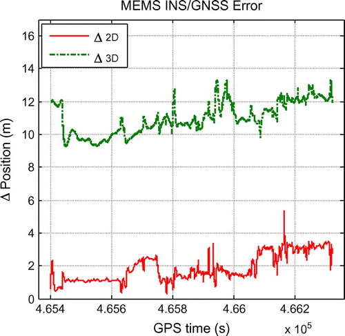
Table 6. Position error-RMS comparison.
4.2.2 Simulated GNSS outages
Four 30-second-duration GNSS outages are simulated to further assess the improvement of DAV over AV in the MEMS INS/GNSS integration.
Figures show the 2D and 3D errors of the MEMS INS/GNSS. As expected, its navigation solution drifts unboundedly over time without the aiding of GNSS. It is observed that the DAV-EKF results in smaller 2D and 3D errors, compared to AV-EKF. This is due to DAV being able to provide a more realistic estimation of INS stochastic errors, thus, allowing the EKF to better estimate INS biases. As shown in Tables, the improvement ranges from 2.840 to 4.600 m and 1.474 to 8.850 m for 2D and 3D errors, respectively. On average, the 2D and 3D positional errors improved by 3.559 and 5.749 m, respectively.
Figure 9 AV-EKF vs. DAV-EKF 2D performance.
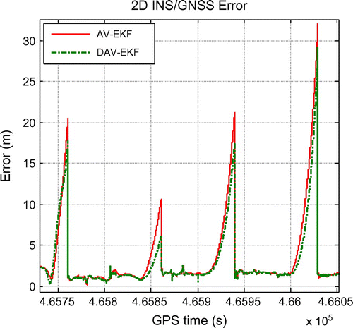
Figure 10 AV-EKF vs. DAV-EKF 3D performance.
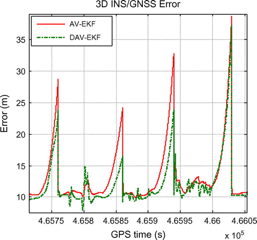
Table 7. 2D maximum error during GNSS outage.
Table 8. 3D maximum error during GNSS outage.
5 Conclusions and future work
This paper has identified INS stochastic errors using AV applied on static data and DAV applied on kinematic data. The results from AV show that the dominant INS error is the A/VRW, resulting from white noise in the INS measurements. The AV also allows for identification of measurement bias instabilities. The results from DAV show that INS measurement errors are influenced by vehicle motion and environment. The error coefficients were used in the EKF integration algorithm and analysed using real kinematic data. The results show that INS/GNSS using error coefficients extracted with DAV gave a slight improvement over AV, as DAV accounts for errors associated with vehicle motion and vibration. Therefore, it is recommended that INS/GNSS integrated systems take into consideration the effects of vehicle motion and environment using DAV.
Various recommendations can be made for future work to detect INS dynamic dependent errors. As presented in the DAV analysis, the effect of motion can be observed in the DAV graph, through a variation of . In the DAV-EKF analysis, only the maximum
was used. This assumes the worst-case scenario, which subsequently results in a non-optimal usage of the extracted information. It would be more desirable for different
, depending on the vehicle motions, were applied in the integration algorithm. This requires a vehicle motion detection and classification, to allow the integration algorithm to use the most appropriate
value.
Notes on contributors
Azmir Hasnur-Rabiain is a PhD. candidate in The University of Melbourne. He received his bachelors and masters by research of Geomatics Engineering degrees from the University of Melbourne in 2008 and 2011 respectively. His research interest includes cooperative positioning and integrated navigation systems.
Allison Kealy is an associate professor in The University of Melbourne and has been a researcher in sensor fusion and satellite positioning systems for almost two decades. Her research interests are in sensor fusion, Kalman filtering, GNSS quality control, with application in wireless sensor networks and location-based services.
Mark Morelande received the B.Eng. degree in aerospace avionics from Queensland University of Technology, Brisbane, Australia in 1997 and the PhD. in electrical engineering from Curtin University of Technology, Perth, Australia in 2001. In 2001 he was a Postdoctoral Fellow at the Centre for Eye Research, Queensland University of Technology. From 2002 to 2005 he was a Research Fellow at the Cooperative Research Centre for Sensor, Signal and Information Processing, University of Melbourne. He is now a Senior Research Fellow in the Melbourne Systems Laboratory, also at The University of Melbourne. His research interests include non-stationary signal analysis and target tracking with particular emphasis on multiple target tracking and sequential Monte Carlo methods.
References
- Groves, P.D. Principle of GNSS, Inertial, and Multisensor Integrated Navigation Systems; Artech House, Boston, MA, 2008.
- IEEE. IEEE Standard Specification Format Guide and Test Procedure for Linear Single-Axis, Nongyroscopic Accelerometers, IEEE Std. 1293–1998; Technical Report, Institute of Electrical and Electronics Engineers Standards Association, 1998. http://ieeexplore.ieee.org/xpl/articleDetails.jsp?tp=&arnumber=782464&url=http%3A%2F%2Fieeexplore.ieee.org%2Fxpls%2Fabs_all.jsp%3Farnumber%3D782464.
- El-Sheimy, N.; Hou, H.; Niu, X. Analysis and Modeling of Inertial Sensors Using Allan Variance. IEEE Trans. Instrum. Meas. 2008, 57 (1), 140–149.
- Han, S.; Wang, J.; Knight, N. Using Allan Variance to Determine the Calibration Model of Inertial Sensors For GPS/INS Integration. 6th International Symposium on Mobile Mapping Technology, Sao Paulo, Brazil, 2009.
- Zhang, X.; Li, Y.; Mumford, P.; Rizos, C. Allan Variance Analysis of Error Characteristics of MEMS Inertial Sensors for an FPGA-based GPS/INS System; International Symposium on GPS/GNSS, Tokyo, 2008.
- Hasnur-Rabiain, A. Performance Evaluation of MEMS based INS/GPS Integration. Master’s Thesis, The University of Melbourne, Melbourne 2010.
- Hou, H. Modeling Inertial Sensors Errors Using Allan Variance. Master’s thesis, Department of Geomatics Engineering, University of Calgary, Calgary, 2004.
- El-Diasty, M.; Pagiataki, S. Calibration and Stochastic Modelling of Inertial Navigation Sensor Errors. J. Global Positioning Systems 2008, 7 (2), 170–182.
- Wis, M.; Colomina, I. Dynamic Dependent IMU Stochastic Modeling for Enhanced INS/GNSS Navigation. 5th ESA Workshop on Satellite Navigation Technologies and European Workshop on GNSS Signals and Signal Processing (NAVITEC), Noordwijk, Netherlands, 2010.
- Jain, S.; Nandy, S.; Chakraborty, G.; Kumar, C.; Ray, R.; Shome, S. Error Modeling of Various Sensors for Robotics Application using Allan Variance Technique; IEEE International Conference on Signal Processing, Communications and Computing (ICSPCC), Shaanxi, 2011 China.
- Galleani, L.; Tavella, P. The Dynamic Allan Variance. IEEE Trans. Ultrason. Ferroelectr. Freq. Control 2009, 56, 450–464.
- Galleani, L. The Dynamic Allan Variance II: A Fast Computational Algorithm. IEEE Trans. Ultrason. Ferroelectr. Freq. Control 2010, 57, 182–188.
- Galleani, L. The dynamic Allan Variance III: Confidence and Detection Surfaces. IEEE Trans. Ultrason. Ferroelectr. Freq. Control 2011, 58, 1550–1558.
- Hjortsmarker, N. Experimental System for Validating GPS/INS Integration Algorithms; Master’s Thesis, Computer Science and Electrical Engineering, Lulea University of Technology, Lulea, 2005.
- Stockwell, W. Bias Stability Measurement: Allan Variance; Technical Report, Crossbow Technology, Inc., 2004. http://www.xbow.com/Literature/Application_Notes_Papers/Gyro_Bias_Stability_Measurement_using_Allan_Variance.pdf.
- Stockwell, W. Angle Random Walk; Technical Report, Crossbow Technology, Inc., 2004. http://bullseye.xbow.com:81/Support/Support_pdf_files/AngleRandomWalkAppNote.pdf.
- Niu, X.; Goodall, C.; Nassar, S.; El-Sheimy, N. An Efficient Method for Evaluating the Performance of MEMS IMUs; IEEE/ION Position, Location and Navigation Symposium, San Diego, CA, 2006.
- Kealy, A.; Retscher, G.; Alam, N.; Hasnur-Rabiain, A.; Toth, C.; Grejner-Brzezinska, D.; Moore, T.; Chris Hill, C.; Gikas, V.; Chris Hide, C.; Danezis, C.; Bonenberg, L.; Roberts, G. W. Collaborative Navigation with Ground Vehicles and Personal Navigators. International Conference on Indoor Positioning and Indoor Navigation, Sydney, Australia, 2012.
- Farrell, J.A. Aided Navigation: GPS with High Rate Sensors; The McGraw-Hill Companies, New York, NY, 2008.