Abstract
GPS-based technology has served the positioning and navigation industry for decades with outstanding reliability and accuracy. However, limitations for location-based services in indoor scenarios remain where GPS signal reception suffers from severe degradation or even outages. Wi-Fi-based positioning is currently the most popular indoor location solution, with an availability and time-to-first-fix that are significantly better than GPS. However, the achievable position accuracy is only at the level of tens of meters on average depending on database density and signal reception quality. In order to improve positioning accuracy and availability, motion sensors like accelerometers, gyros, and magnetic compasses are increasingly integrated into smart devices. However, their position solutions suffer from the effects of significant accumulative errors. In this paper, a vision-based indoor positioning method is developed to overcome the limitations above. The proposed vision-based system relies on a single camera, widely available on smart phones and tablets. The derivation of the absolute 3D position from 2D snapshots of a single camera requires the use of an external geo-reference database. In this research, a ubiquitous floor plan database has been used to provide accurate geodetic information. Unlike other popular geo-reference databases, the database used in this work can easily be generated with existing resources. The proposed system has been developed as an iOS App and was tested on iPad for various indoor scenarios. The results show that the performance of the proposed system is superior to Wi-Fi-based positioning systems.
1. Introduction
Location-based services (LBS) have found a large number of applications in recent years, supported for outdoors by GPS. Unfortunately, GPS positioning performance for indoor environments which account for a significant proportion of LBS applications suffers from severe degradation due to noise, multipath, and signal blockage. The popularity of Wi-Fi networks has boosted the development of Wi-Fi-based indoor positioning systems, which relies on a comprehensive database of the geo-locations and signal strength information of Wi-Fi access points (APs). In addition to the excellent availability and a time-to-first-fix shorter than indoor GPS-based techniques, Wi-Fi positioning accuracy is typically at a level of 5 m. In practice, however, this level of accuracy is limited by the coverage of the database and the received signal strength. According to tests conducted by the authors in various indoor environments, the average Wi-Fi positioning accuracy is at the level of tens of meters. In order to improve the indoor positioning accuracy and service availability, motion sensors are increasingly being integrated to aid the generation of continuous measurements to improve location and orientation information. For example, Melania Citation(1) developed a pedestrian gait estimation method, in which the measurements of the inertial sensors are used to estimate the pedestrian gait frequency and lengths of strides. However, this dead-reckoning system suffers from accumulative sensor bias and drift, especially when using embedded low-cost MEMS sensors resulting positioning errors at the level of tens of meters in less than five minutes. As the requirements for indoor positioning accuracy are typically at the room level or aisle level, Wi-Fi-based positioning and the use of motion sensors have difficulties meeting these requirements.
Given the limitations indicated above, alternative positioning methods are required. Vision-based navigation technologies, originally developed for robotic applications promise to be a viable alternative. The platform of an intelligent robotic vehicle consisting of motion sensors, a GPS module, and vision sensors is in fact quite similar to modern smart devices. This presents a good opportunity to adapt its vision-based navigation methodologies to smart phones and tablets for pedestrian navigation. Traditional vision sensors adopt two or more cameras to form stereo vision. However, multiple cameras are not available on current smart devices. This leads to a particular interest in monocular vision-based navigation methods. A vision-based navigation system using inertial sensors and a camera for smart phones developed by Laura Citation(2) is an example of such methods. A vanishing point tracking technique was employed to derive the absolute heading information to calibrate the gyro bias and drift. The accuracy of this method is however limited due to the relative lack of absolute position calibration. In order to calibrate position errors, it is necessary to overcome the lack of the image-scale information of 2D monocular vision. Hide et al. Citation(3) developed a handheld vision-based navigation system using a ground-facing camera. The camera height to the ground is set to an empirical value so that an imaging scale is available. However, in comparison to a forward-looking camera, the number of distinguishable features is insufficient, quickly disappearing from the camera scene even when users keep to a moderate walking speed.
Another limitation of the above-mentioned vision-based navigation approach is that it requires continuous feature tracking and hence the smart device with the camera to be continuously turned-on. This is not practical for real applications where battery power consumption is a concern. To avoid this, an innovative “landmark recognition” system has gained increasing interest. A landmark recognition system matches a single camera image with the geo-tagged photo database, and when the most similar photo is found, its geo-tag is used to derive the user location. The Google Street View is a well-known example for outdoor applications: survey vehicles equipped with GPS, laser scanners, cameras, and inertial sensors drive through millions of streets around the world to collect the required geo-tagged photos. For indoor applications, the collection of geo-tagged photos would have to mainly rely on the use of high-end robotic vehicles. For example, Yuan et al. Citation(4) used the stereovision-based simultaneously localization and mapping robotic vehicle to collect photos tagged with robotics ego-motion. However, a geo-tagged photo database for both indoor and outdoor applications is not considered a ubiquitous solution, because the data collection, update, and maintenance tasks are costly and time consuming.
In this paper, a pedestrian indoor navigation system, inspired by the landmark recognition system, is proposed. The system employs a single image and a ubiquitous database of the building floor plan, a widely existing resource for every building. Accurate geo-reference information includes the geodetic position, the building heading, and the scale of the drawing. A navigation algorithm which integrates the floor plan geo-reference information with the camera image to derive accurate camera position and orientation is developed. An iOS App was developed to realize the proposed system design and its positioning performance was evaluated on an iPad with 500 indoor tests in various indoor scenarios and compared to Wi-Fi positioning performance. The test results indicate that the proposed system has improved the Wi-Fi positioning accuracy from tens of meters to 5.5 m on average. Furthermore, the system’s fast computation speed also enables real-time implementation for indoor navigation and guidance applications.
2 Floor plan database and indoor hallway features
The definition of a floor plan is a scaled drawing of the top view of the interior structure and arrangement of building layers. For the purpose of construction reference and facility maintenance, the surveyed floor plan should be used as it contains actual measurements of geodetic positions, angles, distances, and areas. This information is typically accurate to the level of decimeters. Most public facilities, such as airports and shopping malls, have provided floor plans on their websites. However, these plans seldom contain geo-reference information. In order to overcome this problem and develop a ubiquitous system, a procedure to generate floor plan databases with geo-reference information is introduced based on the Google Floor Plan Project, as shown in Figure . The steps to generate a customized floor plan database are summarized as follows:
Search the target building on Google Maps and select the floor layer of interest to add the floor plan.
Upload a picture of the floor plan. This floor plan picture does not necessarily contain geodetic information.
Fix three landmarks on the floor plan picture, e.g. the corners of walls, and stretch the three landmarks to coincide with the corresponding landmarks on the outdoor Google Maps, hence aligning the floor plan with the outdoor map as shown in the picture on the right-hand side of Figure .
Tag the geodetic positions and Google Maps on the floor plan picture according to the alignment between the floor plan picture and the Google Maps. This yields the range of the latitude and longitude covered by the floor plan, the scale of the floor plan, and the heading of the floor plan.
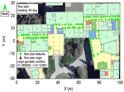
Construct the floor plan frame as shown in Figure and store the available geo-reference information in a database: first, a local origin with a known geodetic position is selected on the floor plan (shown as a red dot); the scale of coordinate axes is then determined from the actual scale of the floor plan; the coordinates in the floor plan frame are transformed into the geodetic frame as the heading of the floor plan is available; finally, floor plan features such as the corner of doorways and walls are added to the database (shown as the green dots). Their positions in the floor plan frame are the most important data for the navigation algorithm proposed in this paper.
Figure 1 Example of generating floor plan geodetic information using the Google Floor Plan project.
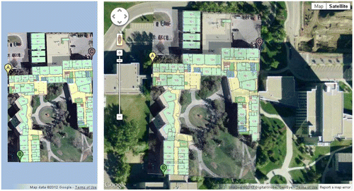
Figure 2 Floor plan frame and geo-reference information.
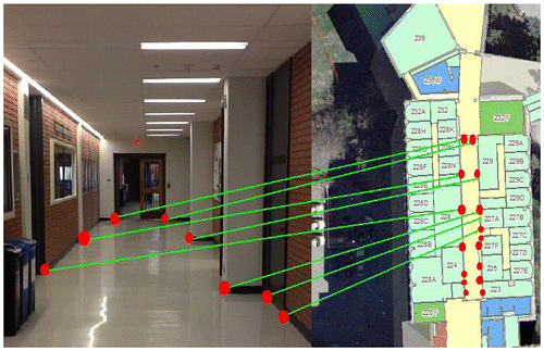
In this paper, the proposed system aims to match the camera image taken in an indoor environment with the corresponding scene contained in the floor plan database to derive the camera position and orientation. Although many indoor objects such as trash bins, bulletin boards, and lights can easily be detected in a camera scene, only features available in both the camera image and the floor plan are relevant targets for matching. These include the corner of doorways and walls, as shown in Figure . These indoor hallway features are reliable for matching for two reasons: first, these indoor hallway features are static while other objects such as trash bins and furniture may move or change; second, unlike the furniture plan or other detailed plan, the floor plan only depicts the abstract interior without detailed objects or appliances. Therefore, only indoor hallway features can be matched to the floor plan.
Figure 3 Correspondences (common points) of indoor hallway features in image and floor plan picture.
3 System design and navigation algorithm
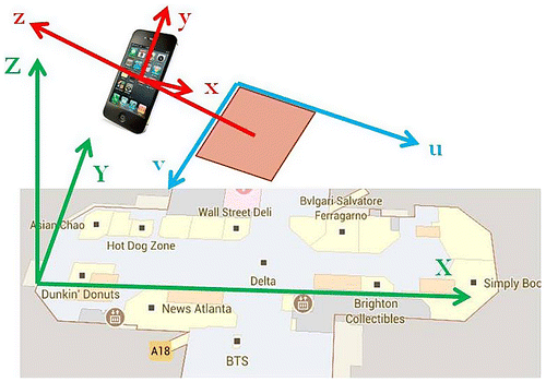
3.1 Definition of frames
All coordinates involved in this paper are expressed in three types of frames: floor plan, camera, and image, as illustrated in Figure and defined below:
Floor plan frame: a three-dimensional frame with the origin selected on the floor plan, x-axis pointing along the hallway, z-axis pointing up and y-axis orthogonal with both;
Camera frame: a three-dimensional frame with origin at the camera perspective center, x-axis pointing right, y-axis pointing up, z-axis orthogonal to the imaging plane;
Image frame: a two-dimensional frame of the camera imaging plane at a distance corresponding to the focal length from the camera perspective center.
Figure 4 Image frame (blue); camera frame (red); floor plan frame (green).
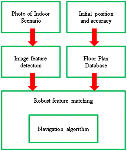
3.2 System flowchart
The flowchart of the proposed system is shown in Figure and the functions of the six major components are described in the following:
Initial position and accuracy: although the default positioning method on a smart device platform is a hybrid solution of GPS/Cellular/Wi-Fi, GPS signals are unavailable in most deep indoor environments. The iPad used in this paper does not have a cellular module, so the initial indoor position relies on Wi-Fi positioning, with its typical accuracy at the level of tens of meters.
Photo of indoor scenario: The user takes an image of the indoor environment, containing as many indoor hallway features as possible (e.g. along the hallway). The user then specifies the indoor hallway features on the image.
Image feature detection: The user determines the search region for feature detection and the image processing method will then be applied to these regions to detect indoor hallway features and extract the exact pixel locations of the detected indoor hallway features.
Floor plan database: The initial Wi-Fi position and accuracy is sent to the server to determine the area of interest, and feedback is then sent to the user including the floor plan features and geo-reference data for the area of interest.
Robust feature matching: the Random Sample Consensus (RANSAC) method, an iterative matching process with random guesses and verification tests, is used.
Navigation algorithm: implemented as part of the RANSAC matching and applied to the random guesses to derive the camera position and orientation. The camera pose is initially derived from the random guess and then validated through a verification test. If the test is passed, the matching is successful and the RANSAC is terminated, otherwise a new random guess is started until the maximum number of iterations is reached. If no random guess passes the verification test while the maximum number of iterations is reached, the matching is unsuccessful and the RANSAC is terminated.
Figure 5 System flowchart.
3.3 Navigation algorithm
The navigation algorithm contains two steps as shown in Figure : the passive ranging method, and the camera position and orientation derivation.
Figure 6 Navigation algorithm.
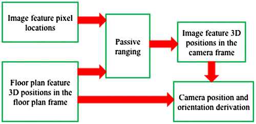
The passive ranging method is originally proposed by Hung et al. Citation(5), and it is modified in this paper as the first step of the navigation algorithm. It takes the inputs of the 2D pixel locations of the image features and the 3D positions of the floor plan features, and outputs the image features’ 3D positions in the camera frame. A monocular image captured by the user camera only contains 2D image features since the imaging scale is unknown. As shown in Equations (1) and (2), the feature 3D position in the camera frame is determined by its pixel location in the image frame and the scale, which is unknown. In order to derive the 3D camera position and orientation from a 2D image, the imaging scale is required. The feature positions in the floor plan frame provide two important constraints for the passive ranging method, namely the length constraint and the coplanar constraint. The passive ranging method requires four features to form a quadrangle pattern; any four coplanar points should satisfy Equation (3). The coplanar constraints are the two constants in Equation (3) which constrain the shape of the quadrangle. By taking Equations (2) and (3), Equation (4) is obtained. However, it does not provide a unique solution to the scale. The length constraint, which is the Euclidean distance between features, as shown in Equations (5) and (6), is also needed. Since the image features’ floor plan correspondences (common points) should also satisfy Equations (3) and (5), the coplanar and length constraints are obtained by introducing the floor plan feature positions in the floor plan frame into Equations (3) and (5). Finally, introducing the derived scales of each image feature into Equation (2) derives the image feature 3D positions in the camera frame.(1)
(2)
(3)
(4)
(5)
(6) where
is the image feature with pixel location
;
is the unknown imaging scale; Q is the feature 3D position in the camera frame; α and β are the coplanar constraints, which describe the coplanar relationship of the four features; and
is the length constraint, the Euclidean distance between features.
The camera position and orientation derivation takes the inputs of the image features’ 3D positions in the camera frame and the floor plan feature 3D positions in the floor plan frame, and outputs the camera position and orientation in the floor plan frame. With the derived image feature positions in the camera frame and their corresponding floor plan feature positions in the floor plan frame, the camera position and orientation determines the transformation process between the two frames as shown in Equation (7). Three pairs of feature positions are sufficient to derive the camera position and orientation, but there are always more than four feature matches. Thus, the second step of the navigation algorithm is to use a minimization approach as in Equation (8) to make two sets of coordinates mutually transformable and obtain the best fit, while keeping the orthogonal property of the camera orientation matrix. Berthold et al. Citation(6) have derived a close-form solution for this problem, and their method is modified in this paper.(7)
(8) where
is the unknown camera position;
is the unknown camera orientation matrix;
is the i-th feature coordinates in the camera frame; and
is its corresponding floor plan feature position in the floor plan frame;
is the total number of image-to-floor plan correspondences. More details about the navigation algorithm can be found in the report by Huang and Gao Citation(7).
4 Indoor tests and performance analysis
This section describes the field tests conducted for different indoor environments on the campus of the University of Calgary, including the experimental method.
4.1 Description of test area and method
The University of Calgary online interactive map is used to generate the floor plan database. Since the scale of the floor plan is a key input for the navigation algorithm, the accuracy of the floor plan scale was validated with actual measurements, accurate at the decimeter level. This floor plan database covers the first level of the Engineering Building A, B, C, D, and E blocks, as shown in Figure . The selection of these five blocks reflects general indoor application environments, which include both standard and irregular structures:
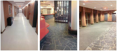
END, EN, C and ENB are the D, C, and B blocks in the Engineering Complex, respectively; these three blocks have parallel hallways with recognizable indoor features as shown in the left picture of Figure . These are the most common indoor environments.
ENE is the ground level of the E block and represents the indoor scenario with irregular shaped hallways, as shown in the middle picture of Figure .
ENA in the A block is the least preferred indoor environment because it is an open area with no hallways available, as shown in the right picture of Figure .
Figure 7 Indoor test areas.

Figure 8 Left: standard hallway of the END block; Middle: irregular hallway of the ENE block; Right: open area of the ENA block.
For the above-mentioned five indoor test areas, 10 indoor landmarks are selected in each area, and at each landmark the iPad App was run 10 times, yielding a total number of indoor tests of 500. For the accuracy analysis, the true positions of the landmarks were also measured from the online interactive map, which is accurate at the decimeter level, and used as the reference.
4.2 Development of the iOS App
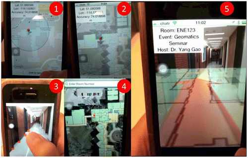
The iOS App realizes the entire system design shown in Figure : the initial indoor location is collected by using the core location framework to output user latitude, longitude, and accuracy; the feature detection is based on the image-processing library Open CV; the communication with the server is simulated using a cloud storage Dropbox where the floor plan database is stored; for RANSAC matching and the navigation algorithm, a linear algebra library LAPACK is implemented. The following description, along with Figure , illustrates how to use this App:
Using the screen shot, the initial indoor location was obtained with an accuracy of 74 m. A “Link to server” button is displayed at the bottom of the screen (see Figure (1)).
After connecting to the remote server, the floor plan centered around the initial location is downloaded and overlaid onto the map (see Figure (2)).
The user takes a photo of the hallway and indicates the indoor hallway features by touching the screen (shown as red dots in Figure (3)).
After executing the navigation algorithm and using the RANSAC matching to derive the camera position and orientation, the user position is pinned on the floor plan (shown as a red dot in Figure (4)). Meanwhile, the user can indicate a destination room.
The derived camera position and orientation enable the software to rotate the floor plan and a navigation arrow to the user perspective, overlaid on a camera view. If an up-to-date database of the room inventory is available, the event in the destination room can also be displayed (see Figure (5)).
Figure 9 Screen shots of iOS App.
4.3 Mean and STD position errors
During the repeatability tests conducted at each landmark, both the Wi-Fi positions and the results derived by the proposed system are recorded. In Figures, the 50 landmarks are shown in circles where different colors represent the magnitudes of the STD error values, while different sizes of the circles represent the magnitudes of the mean position errors. The repeatability of the position STD errors was first analyzed. Referring to the color bar in Figure , the overall STD errors of Wi-Fi positions vary from 1.28 m to 8.17 m, and the STD errors in the END, ENE, and ENA blocks are relatively larger. The inconsistency in the repeatability of the Wi-Fi positions in varying areas is likely caused by the uneven density of the Wi-Fi AP database and the variation in the received Wi-Fi signal strengths. In contrast, the dots in Figure are in relatively cold color, suggesting that the STD errors are significantly reduced by using the proposed system. In particular, a significant improvement was observed in the ENA, END, and ENE blocks. Furthermore, the dots’ color in Figure is much more consistent in each block, demonstrating that the repeatability of the proposed system does not degrade in variable indoor environments. However, it is noticeable that in the middle of the hallways in ENB and ENC blocks there are two red dots with STD errors as large as 9 m. These highlight one limitation of the proposed system, which requires the user to stand near the ends of a hallway and take an image with as many indoor hallway features as possible. Otherwise, the feature matching lacks sufficient details about the indoor structure and arrangement, which may lead to mismatches or matching failures. If the user takes indoor pictures following the suggested protocol, the large STD errors present in ENB and ENC blocks can be avoided, yielding STD errors at the remaining landmarks ranging from 0.22 to 7.25 m.
Figure 10 Initial Wi-Fi-based positions, their mean and STD position error.
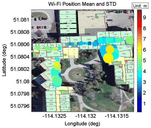
Figure 11 Final derived positions using the proposed system, their mean, and STD position errors.
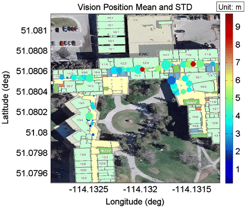
As to the mean position errors, the improvement by the proposed system over Wi-Fi is self-evident. In the ENE block, where the hallway shapes are irregular and in the ENB, ENC, and END blocks with parallel hallways, the smallest mean position errors are at the decimeter level. However, the ENA block with an open area indoor environment appears to be more challenging, with mean errors that are overall larger. Furthermore, a clear trend with the STD errors is found in Figure : in the ENB, ENC, END, and ENE blocks, the mean position errors in the middle of the hallways are always large, while the smallest mean position errors (at the decimeter level) always occur at the ends of the hallways. This finding again emphasizes the importance of the availability of indoor hallway features. In order to obtain reliable details of the indoor environment for feature matching, the user should try to stand near the ends of the hallways to include as many features in the camera image as possible.
4.4 Position RMS error and success rate
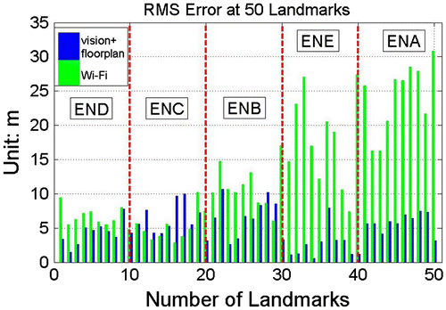
In order to analyse the position accuracy, the RMS errors at the 50 indoor landmarks are illustrated in Figure . Three conclusions can be drawn from the results: (1) due to the uneven coverage and density of the Wi-Fi APs in the database and due to the variability in the received signal strength, the Wi-Fi position RMS errors shown in Figure vary significantly, from 2.8 to 30.8 m. By using the proposed system, the RMS errors are significantly reduced, ranging from 1.1 to 10.7 m. (2) The accuracy of the Wi-Fi positions is significantly variable, while that of the proposed system is consistent for variable indoor environments. (3) The proposed system was shown to be suitable for all five test areas, with significantly variable indoor environments.
Figure 12 RMS position errors at 50 landmarks.
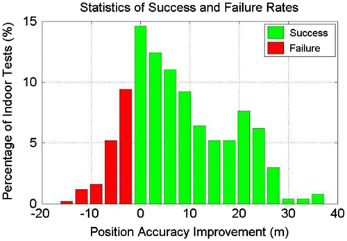
The success rate of the proposed system to provide better results than Wi-Fi is evaluated for the 500 tests. The failure rate (i.e. corresponding to degradation in the accuracy over Wi-Fi), is also investigated. These results are shown in Figure , where the green bars show success results while the red bars show failures. The total success rate is 76%, with accuracy improvements of over 10 m in 59.2% of the results. The total failure rate is 24%. However, 51.7% of these ‘failures’ have in fact comparable performance to Wi-Fi positioning, with an accuracy degradation of less than 3 m. 11.6% of the indoor tests yield significantly worse results than Wi-Fi, with an degradation greater than 3 m. These failures occurred at the landmarks in the middle of hallways in ENB, ENC, and END blocks, emphasizing again the need to take indoor pictures at the ends of the hallways.
Figure 13 Success and failure rates of the proposed system compared to Wi-Fi.
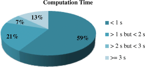
4.5 Computational speed
The feature detection process and the RANSAC matching are the most computing intensive. In this paper, the feature detection is applied only to the regions indicated by user touches, not to the whole image. Therefore, the computational speed for feature detection is very fast. The RANSAC matching is then the most computing intensive part of the system. The computation times are shown in Figure for the 500 indoor tests. 59% of the tests accomplish feature detection, matching, and navigation within one second, sufficient for real-time applications. Thirteen percent tests required more than three seconds, all occurring at the landmarks in the ENB block. This is due to the numerous indoor hallway features in the ENB floor plan database, with more than 20 doorways and other indoor hallway features. The camera view only contains a limited number of the image features and the image features in the camera view do not provide sufficient details about the indoor structure of the ENB block. The matching of such a limited number of features to the large pool of ENB floor plan features is a challenging task for the RANSAC matching.
Figure 14 Statistics on computational speed.
5 Conclusions and future work
An innovative monocular vision-based indoor navigation system has been developed in this paper, in which the camera image is integrated with a ubiquitous database of the building floor plan to derive the 3D camera position and orientation. The proposed system has been tested on iPad in variable indoor environments and its performance has been compared to the Wi-Fi-based positioning solutions. The test results suggest a significant improvement in positioning accuracy and reliability in indoor environments when using the proposed system.
Future work will further improve the overall performance of the proposed system. The integration of a barometer will provide accurate altitude measurements to index the building floor plan database and determine the correct layer. Taking advantage of available motion sensors on a smart device is expected to further improve the initial Wi-Fi position accuracy, and significantly reduce the area for feature detection and matching. This not only can reduce the computational load but also improve the accuracy and reliability of the RANSAC matching.
Notes on contributors
Bei Huang is an MSc student in the Department of Geomatics Engineering at the University of Calgary. She achieved her Bachelor degree in 2009 in the Department of Electrical Engineering at the Huazhong University of Science and Technology, Wuhan, China. Her current research involves multisensor integrated navigation methodology.
Yang Gao is a professor in the Department of Geomatics Engineering at the University of Calgary. His research expertise includes both theoretical aspects and practical applications of satellite positioning and navigation systems. His current research focuses on high precision GPS positioning and multisensor integration system.
Acknowledgements
This research is financially supported by the Natural Sciences and Engineering Research Council (NSERC) of Canada and Tecterra.
References
- Melania, S. Gait Analysis for Pedestrain Navigation Using MEMS Handheld Devices. Master of Science Thesis, Geomatics Engineeirng, University of Calgary, UCGE, Report 20359, September 2012.
- Laura, R. Visual Gyroscope and Odometer for Pedestrian Indoor Navigation with a Smartphone. In , Proceedings of Institute of Navigation GNSS 2012, Nashville, TN, September 2012.
- Hide, C.; Botterill, T; Andreotti M. Vision-Aided IMU for Handheld Pedestrian Navigation. In Proceedings of Institute of Navigation GNSS 2010, Portland, OR, September 2010; pp 534–541.
- Yuan, Z.; Li, X.; Wang, J.; Yuan, Q.; Xu, D.; Diao, J. Methods of 3D Map Storage Based on Geo-Referenced Image Database. Trans. Nonferrous Met. Soc. China 2011, 21 (3), 654–659.
- Hung, Y.; Yeh, P.; Harwood, D. Passive Ranging to Known Planar Point Sets. In Proceedings of IEEE International Conference of Robotics and Automation, St. Louis, MO, March 1985; pp 80–85.
- Berthold, K.; Horn, P.; Hilden, H.; Negahdaripour, S. Closed-Form Solution of Absolute Orientation Using Orthonormal Mareices. J. Opt. Soc. Am. 1988, 5 (7), 1127–1135.
- Huang, B.; Gao, Y. Indoor Navigation with iPhone/iPad: Floor Plan-Based Monocular Vision Navigation. In Proceedings of Institute of Navigation GNSS 2012, Portland, OR, September 2012.