
Abstract
The prospects for expanding the mineral resource base in many countries are linked with the exploration of stranded sites localized at unexplored areas with complex natural and landscape conditions that make any ground survey, including magnetic prospecting, difficult and expensive. The current level of geology requires high-precision and large-scale data at the first stages of geological exploration. Since 2012, technologies of aeromagnetic surveying with unmanned aircraft vehicles (UAV) enter the market, but most of them are based on big fixed-wing UAV and do not allow to substantially increase the level of survey granularity compared with traditional aerial methods. To increase the scale of survey, it is necessary to reduce the altitude and speed of flight, for which the authors develop the methodical and technical solutions described in this article. To obtain data at altitudes of 5 m above the terrain even in a rugged relief, we created heavy multirotor UAVs that are stable in flight and may be used in a wide range of environmental conditions (even a moderate snowfall), and develop a special software to generate flight missions on the basis of digital elevation models. A UAV has special design to reduce magnetic interference of the flight platform; the magnetic sensor is hung below the aircraft. This technology was conducted in a considerable amount of magnetic surveys in the mountainous regions of East Siberia between 2014 and 2016. The results of the comparison between airborne and ground surveys are presented, which show that the sensitivity of the developed system in conjunction with low-altitude measurements can cover any geologically significant anomalies of the magnetic field. An unmanned survey is cheaper and more productive; the multirotor-based technologies may largely replace traditional ground magnetic exploration in scales of 1:10,000−1:1000.
1. Introduction
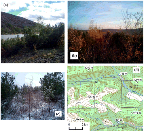
Stocks of easily discovered deposits have been mostly depleted. The prospects for expanding the mineral resource base are leading to studies of stranded sites localized at underexplored areas with complex natural and landscape conditions (Figure ). These factors make any traditional ground geophysical and other survey assignment difficult and very expensive. However, it is obligatory to apply the more effective methods to enable exploration of such areas not only quickly and cheaply but also in sufficient detail (as per Russian Classification in scales of 1:10,000 or larger). One of the most universal geophysical prospecting methods is magnetic survey. Due to attenuation of the magnetic field anomalies with altitude and rugged relief, a classical aeromagnetic prospecting is unable to provide a detailed large-scale survey. Technical improvement of classical geophysical prospecting methods does not resolve the essential problem of cost-effective and operational research of perspective areas. Therefore, an entirely new approach is required for the geological and geophysical work assignments.
Figure 1. Typical environmental conditions of study area: (a) September 1st, (b) September 10th, (c) September 20th, (d) fragment of topographic map.
Nevertheless, the low-altitude survey as an approach enabling geological mapping and detailed geological exploration, are evident since the end of the last century (Macnae Citation1995; Vorobyov et al. Citation1995). Currently, dynamically developing technology of unmanned aerial vehicles (UAV) reduces the risks of the low-altitude survey. Such technologies have not yet taken a significant share of geological prospecting and exploration market. The prospects for development of this direction are obvious; there are examples of created UAVs for aeromagnetic survey (Caron et al. Citation2014; Wood et al. Citation2016) and others over the last few years. The available systems, such as Venturer AS, allow to make aeromagnetic survey at altitudes at least 50 m without the need for airdrome and the cost of flying hours of large aircraft, which significantly increases the cost-effectiveness of small- and medium-scaled magnetic survey. However, these systems are still implemented on sufficiently large aircrafts (several meters in size), and therefore, are characterized by many disadvantages that prevent detailed survey of areas with rugged topography. The major disadvantages are the complexity in transportation, the need for prepared landing strips, and the lack of maneuverability in limited spaces, impossibility to fly in mountainous areas with complex terrain relief. Consequently, these systems do not allow to substantially increase the level of survey scale and granularity as compared with traditional aerial methods based on manned airplanes or helicopters.
The accuracy and correctness of a magnetic survey may be improved by further reducing of measurement altitude that requires the flight with constant elevation above the terrain and lower flying speed (as well as some other methods, such as airborne gamma-spectrometry and LiDAR scanning). Over recent years, the authors have been developing a complex low-altitude remote sensing methods, which would be equally effective in any landscape and morphological conditions and solve the same geological problems as traditional ground surveys. The basis of these complex remote sensing technologies is geophysical methods. A magnetic survey technology named SibGIS UAS (unmanned aerial system), started in 2014, has been tried out and tested first (Parshin Citation2015; Parshin et al. Citation2016). In this paper, the authors presented aeromagnetic data acquired by modern version of SibGIS UAS in comparison with ground magnetic survey within several areas of Bodaibinsky synclinorium (East Siberia, Russia, possible gold ore deposits).
The magnetic surveys have been carried out within the first stages of geological prospecting of geologically underexplored area. But the geological data of more detailed scale (>1:200,000) are not yet available for study area. For the legal restrictions, the authors do not have the rights to make the full scope of obtained data available for public review. Nevertheless, subsoil license owners kindly allowed publishing some survey extracts in public sources.
2. Software and hardware
The SibGIS UAS technology is now available for scales of 1:10,000 or larger and is optimal for being used during the prospect evaluation and exploration survey at individual licenses sites of several hundred square kilometers. These scales of magnetometer survey are the most popular in the Russian practice of prospect evaluation and exploration survey of ore minerals, especially gold. Since the maximum effect from UAS magnetic survey technology can be achieved in complex natural and landscape conditions, one should take into account the potential risks of loss of or damage of equipment. Thus, only low-cost components, easy maintenance and high reliability can provide increased economic efficiency for the technology. The cost of a fully designed airmobile unit is accordingly comparable with that of one modern handheld magnetometer.
Flying at very low altitude with precise draping the terrain surface (required by the objectives and specific natural conditions of the studied areas), reliability and easy transportation require the most suitable multirotor scheme of UAV. The advantages and disadvantages of the various schemes of the UAV for geophysical survey are described in works of Kroll (Citation2013). The disadvantages of the fixed-wing aircraft are described in previous section. The existing gasoline helicopters, which provide a significant take-off weight, are too big, too expensive, and rather complex for maintenance for any long geological expedition.
For surveying, we create two multirotor UAVs and the software for flight missions and data processing. Despite the fact that the air drones are made directly by the authors and are non-serial products, their hardware design comprises the maximum number of components available at the open market on Asian web resources enabling the high maintainability.
First, the “heavyweight” UAV is a six- or eight-rotor copter equipped with magnetometer that measures the module of total geomagnetic field vector (Figure ). Its design was developed to reduce magnetic interference of the flight platform, including multiple levels of vibration isolation, layout solutions that minimize interference from power lines to electric motors, and mounted magnetometer sensor offsets, which are aimed at preventing its rotation regardless of the flexibility.
Figure 2. “Heavyweight” multicopter with magnetometer in flight.
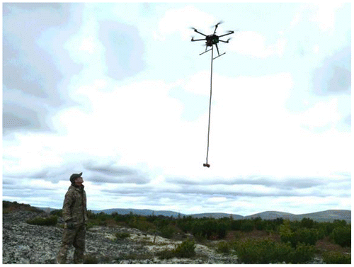
The quantum Overhauser magnetometer is currently used as a magnetometric channel with absolute accuracy within 1 nT when measuring one time per second and maximum frequency measurement 8 Hz. This magnetometer is made as per design specifications which were developed following the 2014−2015 test results for various types and constructions of magnetometers. In its design, we used hardware components of the popular Russian magnetometer MMPOS-1 (from Quantum Magnetometry Laboratory of Ural State Technical University), which provide metrological precision of survey with widespread magnetic base stations.
The take-off weight of “heavyweight” UAV magnetometer may reach up to 15 kg with several LiPo 16,000 mAh batteries installed. Flight time is 20−30 min per battery. Any reduced unit weight will increase the flight time, but our priorities are durability, maintainability, and reliability. The use of relatively larger multirotor UAV allows to flight effectively against wind and snow due to its large weight and high capacity, and then enables to keep a stable flight path and a constant speed that is necessary to obtain high-quality geophysical survey data. The stable video sample recorded in flight can be found in Google drive of Parshin (Citation2017). From the video, you can find that the significant mass and speed of the UAVs allow stabilizing the sensor in flight and preventing its shifting.
For easy transportation, our package is foldable and can be placed in carrying case (backpack). So two men can carry the full equipment set (the UAV, one gasoline generator, one laptop, one ground station, several batteries, and chargers) and perform at a considerable distance from the infrastructure, where no off-road truck could pass.
Manual mode of UAV controlling means operator has to manually keep up with the low and constant altitude, this makes the surveying impossible in complex mountainous areas, and also is not directly allowed by the current Russian aeromagnetic exploration manual. Therefore, in an automated flight, the measurements are normally been taken in automatic mode and stored in the memory, as well as coordinates recorded via GNSS positioning system that supports GLONASS/GPS/Beidou. LiDAR scanner can be installed as an additional load to obtain a high-precision digital terrain model (DTM), which subsequently allows more accurate inversion of magnetic survey data. Flight speed usually ranges from 7 to 10 m/s. When the battery is running down, the aircraft returns to the base for battery replacement and updating the flight mission. Continuous operation mode needs more LiPo batteries and gasoline generators for battery recharging.
Autopilot requires solving the issue of fast creating of correct flight missions based on topography, which is necessary for practical implementation of qualitative survey on large areas in rugged relief. Draping the topography of the surface on maximally possible low altitude is the key aspect in developing the magnetometric technology as a potential replacement for ground surveys, because the magnetic field intensity significantly changes with altitude. So the highly frequent anomalies caused by small-sized geological objects attenuate much faster than the anomalies from large structures. In order to record anomalies of small size or amplitude, which are significant in geological terms, we sought to achieve flights at altitudes of no more than 5 m above the vegetation. To achieve the proposed automated flight, we have to address three main problems.
The first problem is to obtain topographic data comparable in scale with the scale of survey, for the data would possibly create flight missions. Most of the territory of eastern Siberia is covered only by a 1:100,000 scale topographic survey. In the sites with northern latitude up to 60 degrees, the digital elevation model (DEM) SRTM 1-arcsecond is available. As a result of approbations, the model is combining SRTM DEM with available topographic data that enables us to create DTMs suitable for flights at altitudes of 25 m in areas with mid-mountain relief. In other cases, as well as if it is necessary to obtain data at a lower altitude, a photogrammetry technology is created, and a second previously mentioned UAV is used for those cases. The amateur aerial photography market allows us to create our photogrammetric technology very quickly and without significant costs. The second “lightweight” UAV is the 750-class quadrocopter, equipped with real-time kinematic (RTK) positioning system as well as video and photo cameras, and its flight time is 45−50 min. We use a 16 Mp action camera with replaced optics without distortion, which can obtain images with quality high enough to build digital models of 1:2000 scale. In case the first variant of creating a DTM (based on topographic data and global DEM) is applied, this multicopter is used for preliminary verification of flight missions. Availability of a videolink can overtake the control of the UAV while it goes beyond the line of sight (if required).
The second problem is the fairly limited number of flight mission waypoints stored in memory, while low-altitude geophysical surveys in regions with highly dislocated terrain is performed. Thus, for the first complexes (2014−2015), we used the widespread market-available controllers from DJI, which have sufficiently high performance and reasonable price, but the number of supported waypoints in the most popular versions of these controllers ranges from 16 (for hobby-level, DJI NAZA V2) to 50 (for industrial-level, DJI WookongM A2) chipsets. As the operating practice has shown, the high-end controller does not necessarily ensure a quality of high stabilization of the UAV with magnetometer. This phenomena is caused by the more accurate rating of the multicopter’s gravity center parameter for advanced models, and in this case, the UAV’s gravity center is floating because of the hangeth sensor and the sensor-connecting cable. On the other hand, an insufficient amount of waypoints in the entry- and hobby-level controllers leads to insufficiently accurate relief approximation, which reduces the correctness of acquired data, and may even lead to the aerial vehicle crash. The small number of waypoints is a significant factor that limits the flight time and distance, and, ultimately, the performance of the method. In current version of SibGIS UAS technology, SmartAP and TopXgun controllers support more than 100 flight points and resolve the problem of point shortage. To hold a constant height from the sensor to the ground, an array of flight mission points is now created with a step of 30−40 m between neighbor points on the profile. But that did not solve the problem of automated generating of flight missions, and this leads to the third problem.
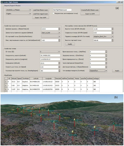
The third problem of the draped aerial survey arranging is the limitations of standard software of ground stations. In most standard software products, there are several major disadvantages: unavailable spatial data that differs from the manufacturer’s references (usually it is insufficiently precise DEM SRTM 3-arcsecond (Figure )), the possibility of automated formation of flight missions with only the same altitude of mission points relative to the take-off point, disabled automated generation of flight missions with set increments between survey profiles, and the possibility of orienting only to the built-in map (usually, Google Map) which is characterized by low quality in the case of remote areas. As to these shortcomings of standard software, there are a wide variety of customized solutions on the market. For example, the Drone Deploy Service (Citation2016) specialized for professional photogrammetry and aerial video surveys. But these solutions do not meet the requirements of low-altitude geophysical survey, so we develop the special software which allows us to create flight missions in the form of regular networks of profiles and pickets based on any user-defined DEMs. Data format of flight mission points for most flight controllers is open, that enable us to develop a plugin for QuantumGIS, named as SibGIS Flight Planner. A simplified module version, which does not have the intellectual capacity to optimize the location of key flight mission points along the terrain, nevertheless enables generating the flight mission with any format of DEMs and exports missions to *.awm format (for DJI controller, published under the open source license available for download) (Morozov and Parshin Citation2016). The developed module enables to perform the following operations: selection of survey profile direction, arrangement of layout of survey stakes with set spacing between profiles and pickets (in an open version), optimization of the flight assignment (not run in an open version), extraction of altitudes from the DTM, configuration and export of the flight mission. The last interface window of our software system is shown in Figure . It is possible to assign the wide range of parameters, such as altitude, speed, or overturning mode at each point. DTMs with required accuracy may be created by standard GIS tools.
Figure 3. Difference between SRTM 3-arcsecond and LiDAR terrain models (visible difference in tens of meters, which show the impossibility of performing a low-altitude magnetic survey in mountainous areas using global DEM).
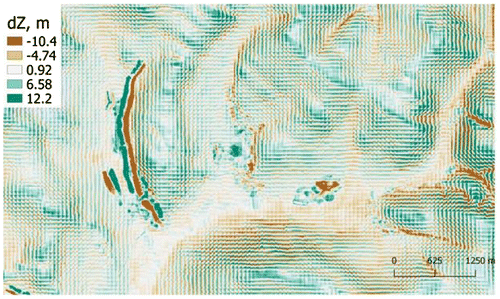
Figure 4. Interface of module SibGIS flight planner for preparation of flight missions (a) and flight mission exported in DJI ground station program (b).
Finally, we managed to achieve those impossible missions by standard tools: precise positioning of all waypoints, preparation of the flight missions in field works, and delay-free surveying. Integration with GIS software ensures generating of the flight mission with all the available spatial data about survey area.
3. Results and discussion
The implementation of all the above solutions made it possible to create a set of effective magnetic survey technologies, which are now widely used. The survey analyzing below was conducted in Summer−Autumn 2016 at wide temperature ranging from −10 to + 25 °C, with wind gusts up to 10−12 m/s, rain, and snow, all these fully test the performances of our created airborne system. The relief is characterized by typical for North Transbaikalia natural conditions: slope angles inclined to 40%, pine bush thickets, scree debris, and wetlands (Figure ).
The survey was concluded on Scale 1:10,000 and 1:5000 (profile spacing 100 and 50 m, respectively). In both cases, the distance between the pickets along the profile amounted to 5 m. Figure shows the surveying fragment of site N1. Hereinafter, the magnetic survey results are shown in view of geomagnetic field variations, but without any additional processing.
Figure 5. Total magnetic intensity map of site N1 (Sensor height: 20 m).
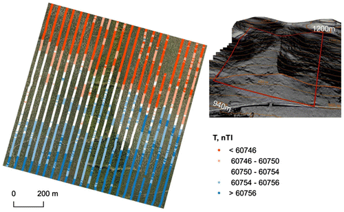
The field of this area N1 is low-contrast, and the profile’s variability does not exceed a few nT, which is considerably less than daily geomagnetic variations. Accordingly, this site is a very complex target for magnetic survey: error up to 2 nT will significantly distort the field image, and error up to 5 nT (only allowable for large-scale survey, as per the Russian (USSR Ministry of Geology Citation1981), and typical for the technology of the first 2014−2015 versions (Parshin Citation2015; Parshin et al. Citation2016)) are unacceptable. On this fragment with clear zoning background, noticeable minor occurs, but anomalies of increased field amplitude values up to 3 nT with nearly E−W trending, which indicates the high technology sensitivity.
Figure shows the fragment of magnetic field map for site N2, in order to compare the results obtained by ground and UAV-surveying data.
Figure 6. Total magnetic intensity map of site N2, obtained by UAV technology (a) and compared with ground survey data (b) (sensor height: 20 m).
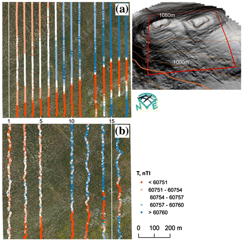
At this site N2, an anomaly of lower field occurs at amplitude of up to 30 nT with nearly E–W trending. The comparison of ground and aerial survey data enables us to recognize a good convergence, the visible zonation of the field coincides (Figures (a) and (b)). Attention is drawn to the increased dispersion in ground survey data, which in this case is not indicative of greater detail of the magnetic survey, but is due to the fact that handheld survey operators have been forced to literally forge through dense thickets and wet bushes, which affects the accuracy of measurements. The profile pre-surveying and cutting operations for magnetic prospecting is currently not used in the Russian practice, because it is regarded as a cheap and fast site survey method, but the operations mentioned in conjunction with expenditures for forest clearing permits completely level out its effectiveness. Unmanned airborne geophysics is free of such problems, and it also acquires data much more convenient for mathematical processing and solving the inverse problems because of its regular nature.
Figure shows the fragment of magnetic field for site N3. This site is located on top of mountain ridge, and therefore, the magnetic survey was conducted with gusts of wind up to 12 m/s, but it is not significantly reflected on the data, our UAV multirotor effectively resisted the wind, and the measurement profiles remained straight.
Figure 7. Total magnetic intensity map of site N3 (sensor height: 10 m).
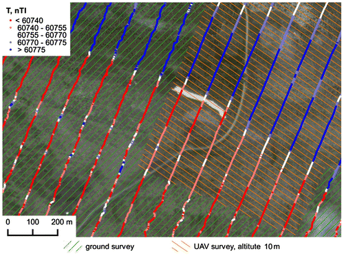
Field map confirms the high convergence of ground and aerial surveying even without field altitude re-adjustment, and suggests that the ground and low-altitude aerial survey under real survey conditions are recording the same geophysical anomalies. The magnetic anomalies within a smaller area, noted on several profiles by ground survey, are also recorded by the UAV, although with a slightly smaller amplitude.
Generally, it may be noted that due to the constant speed and lower impacts on sensor under difficult natural conditions, the unmanned technology provides the high-quality data exceeding that of ground-based measurements. This statement is valid assuming that ground surveys are carried out without profile pre-surveying and forest-cutting operations, which usually occurs in the modern geological exploration practice.
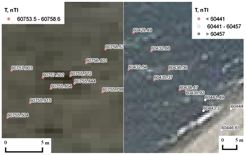
Accuracy of the measurement range of a UAV system has been tested by tie-line and periodically re-routing flights over the same profile (Figure ). The standard deviation of aeromagnetic survey from the difference between the ordinary and repeated observations is less than 2 nT, which is 2.5 times more accurate than what has been prescribed in the magnetic survey instruction manual (USSR Ministry of Geology Citation1981).
Figure 8. Data quality assessment by tie-line.
It should be noted that the estimated cost of ground magnetic prospecting without profile deforestation is at the rate of 1000 USD per km2 in scale 1:10,000, while SibGIS UAS aerial surveying is cost-effective even at the rate of 450 USD per km2, or about 40 USD per linear km.
4. Conclusions
It is worth mentioning that the sensitivity of our developed system in conjunction with very low-altitude measurements is enough to detect any geologically significant anomalies of the magnetic field. The ground survey data have no obvious advantages as compared with the UAS survey data. And the UAS technology multiply reduces the expenditures and improves the work efficiency. We consider 1:5000 the most practical scale for prospect evaluation survey of understudied sites, while the magnetic survey of large areas by ground method in that scale is not cost-effective in terms of the current geological and economic conditions of Russia.
The created SibGIS UAS technology may be used in a wide range of environmental conditions. Heavy-weight multicopters proved to be fully justified for complex environment, since the lighter copter could not effectively resist precipitations (rain and snow) and wind.
According to our experience, multirotor UAV-based magnetic prospecting can be considered as the technology that may largely replace traditional ground magnetic surveys methods in scale of 1:10,000−1:1000 for inaccessible areas with rugged reliefs and during the winter.
Funding
Th is work was supported by the Council on grants of the President of the Russian Federation [Grant Number MK-3608.2018.5].
Notes on contributors
Alexander V. Parshin graduated from Irkutsk National Research Technical University in 2008 and received his PhD degree in 2012. He is the founder and scientific director of the Joint Laboratory of Geoinformatics at the Institute of Geochemistry and Irkutsk, National Research Technical University, and the founder and general director of SibGISTech LLC. His scientific interests include open GIS technologies, remote sensing in geological prospecting, geostatistics, and geoecology.
Vladimir A. Morozov graduated from Irkutsk State University in 2009. He is the chief programmer of SibGISTech LLC. His current research interests are in the field of mathematical programming.
Anton V. Blinov graduated from Irkutsk National Research Technical University in 2015. He is currently a PhD candidate of Vinogradov Institute of Geochemistry SB RAS. His scientific interests include remote sensing, geological and geochemical information processing methods.
Alexey N. Kosterev graduated from Irkutsk National Research Technical University in 2015. He is currently a PhD candidate of Vinogradov Institute of Geochemistry SB RAS. His scientific interests include 3D modeling of geochemical and geophysical fields.
Alexander E. Budyak graduated with a PhD from Irkutsk State University in 1999. He is the head of ore geology lab at Vinogradov Institute of Geochemistry SB RAS, and the chief geologist of SibGISTech LLC. He has engaged in the study and exploration of gold and uranium deposits in Eastern Siberia for over 15 years.
Acknowledgment
My sincere gratitude goes to Vyacheslav Miklyaev, the chief geologist of GVGOLD, and Evgeny Bozhko, the chief geologist of Kopy Goldfields AB, for the opportunity to publish the survey fragments used in this paper.
References
- Caron, R. M., C. Samson, P. Straznicky, S. Ferguson, and L. Sander. 2014. “Aeromagnetic Surveying using a Simulated Unmanned Aircraft System.” Geophysical Prospecting 62 (2): 352–363. doi:10.1111/1365-2478.12075.
- Drone Deploy Service. 2016. “DroneDeploy.” https://www.dronedeploy.com/.
- Kroll, A. 2013. “Evaluation of an Unmanned Aircraft for Geophysical Survey.” Paper presented at the 23rd International Geophysical Conference and Expedition, Melbourne, Australia, August 11–14. doi: 10.1071/ASEG2013ab328.
- Macnae, J. 1995. “Design Specifications for a Geophysical Unmanned Air Vehicle Assembly (GUAVAS).” SEG Technical Program Expanded Abstracts, Houston, USA, October 8–13. doi: 10.1190/1.1887449.
- Morozov, V. A., and A. V. Parshin. 2016. “SibGIS Flight Planner.” https://github.com/raulett/SibGIS-Flight-Planner.
- Parshin, A. V. 2015. “Prospects of Using Drones for Geological Exploration for on the Ore Deposits at Baikal Mountainous Area.” Problems of Natural Sciences 6: 97–101. ( in Russian).
- Parshin, A. V. 2017. “Stable Video Sample Recorded in Flight.” https://drive.google.com/open?id=0B2TJkeSH8LcYSkMzZjFXM0ZBeHM.
- Parshin, A. V., V. S. Kanaikin, A. V. Blinovand, and A. O. Mikhalev. 2016. “Cost-saving Low-altitude UAV Magnetic Survey Technology and its GIS Software.” Paper presented at the 15th EAGE International Conference on Geoinformatics – Theoretical and Applied Aspects. doi: 10.3997/2214-4609.201600547. ( in Russian)
- USSR Ministry of Geology. 1981. Magnetic Survey Instruction Manual. Leningrad: Nedra. ( in Russian).
- Vorobyov, V. P., V. A. Glagolev, V. N. Kirsanov, A. S. Nakhabtsev, V. V. Filimonov, and V. S. Tsirel. 1995. “Perspectives of Using Airborne Geophysical Methods for Detailed Explorations.” Geophysical Instruments 100: 8–15.
- Wood, A., I. Cook, B. Doyle, M. Cunningham, and C. Samson. 2016. “Experimental Aeromagnetic Survey Using an Unmanned Air System.” The Leading Edge 35 (3): 270–273. doi:10.1190/tle35030270.1.