
 ?Mathematical formulae have been encoded as MathML and are displayed in this HTML version using MathJax in order to improve their display. Uncheck the box to turn MathJax off. This feature requires Javascript. Click on a formula to zoom.
ABSTRACT
With the development of the Low Earth Orbit (LEO) communication constellations, it has become a hot area of research to provide additional navigation augmentation services. Limited by volume, weight, power consumption, and running time, the in-flight performance of navigation augmentation payload remains to be investigated. In this paper, we analyze the data quality of on-board GNSS observation and evaluate the precision of short-arc dynamic Precise Orbit Determination (POD) performance based on the WangTong-01 (WT01) mission. Furthermore, the downlink navigation measurement data of WT01 satellites are analyzed and compared with the GNSS observations. The results show that the average multipath errors of the WT01 on-board GPS L1, L2 and BeiDou Satellite Navigation System (BDS) B1, B2 code observation are 0.54, 0.74, 0.65, and 0.58 m, respectively. The short-arc dynamic POD three-dimensional (3D) overlapping accuracy is 7.1 cm. The average multipath errors of downlink navigation signal Z1 and Z2 are 0.81 and 0.80 m, respectively, which at the same order of magnitude as GNSS signals. The maximum Carrier-to-Noise Ratio (C/N0) value of WT01 downlink measurement data can reach 60 dB Hz, which is much stronger than GNSS and indicates the navigation signals of LEO satellites can meet the basic requirement of navigation augmentation.
1. Introduction
Low Earth Orbit (LEO) communication satellite constellation construction has been one of the current development trend today. Iridium is the world’s first completed LEO communication satellite constellation (Maine, Devieux, and Swan Citation1995) and has replaced its existing constellation by sending 75 Iridium NEXT satellites into space in early 2019 (https://spacenews.com/spacex-completes-iridium-next-constellation). SpaceX is building and launching up to 12,000 Starlink satellites and has filed regulatory paperwork with the United Nations’ International Telecommunications Union for another 30,000 satellites (https://spacenews.com/spacex-becomes-operator-of-worlds-largest-commercial-satellite-constellation-with-starlink-launch). There are other large LEO communication constellations under construction, such as OneWeb (https://www.space.com/28307-virgin-qualcomm-oneweb-satellites.html), Samsung (https://www.digitaltrends.com/computing/samsungs-space-internet-could-provide-the-whole-world-with-affordable-internet) and Boeing (https://spacenews.com/boeing-proposes-big-satellite-constellations-in-v-and-c-bands). Some scholars have carried out GNSS navigation augmentation research based on LEO constellation, like iGPS. The iGPS technology concept aiming to complete the augmentation, supplement, and backup of GPS Position, Navigation, and Timing (PNT) performance based on the Iridium constellation (Pratt et al. Citation2013). The Satellite Time and Location (STL) service introduced by the Iridium constellation is an implementation of the iGPS concept, which fully demonstrates the potential of the LEO constellation for navigation augmentation service (https://satelles.com/wp-content/uploads/pdf/Satelles-White-Paper-2019.pdf).
It has become a research hotspot to provide additional navigation augmentation service by attaching navigation payloads to LEO communications satellites. The current GNSS can provide PNT services for a wide range of areas (Larson et al. Citation2008; Larson and Nievinski Citation2013; Hao et al. Citation2018), and its basic navigation services can provide a positioning accuracy of 10 m (Yang et al. Citation2019; Yang, Mao, and Sun Citation2020; Montenbruck, Steigenberger, and Hauschild Citation2020). GNSS precise point positioning (PPP) can obtain centimeter-level positioning accuracy, but generally requires several tens of minutes of convergence time (Cai et al. Citation2015; Erol, Ozulu, and Ilçi Citation2021). The current Ground-Based Augmentation Systems (GBAS) and Satellite-Based Augmentation Systems (SBAS) can effectively improve the positioning accuracy of GNSS, but both of them are regional systems, which can only provide high-precision positioning services for users within their covered areas (Belabbas et al. Citation2008; Walter Citation2017). LEO satellites provide a good opportunity for the augmentation of GNSS performance (Reid et al. Citation2018; Zhang and Ma Citation2019). On the one hand, LEO satellites, as motion monitoring stations, can obtain the precise orbits of GNSS satellites based on a small number of ground stations (Geng et al. Citation2007; Zhao et al. Citation2017). On the other hand, as a navigation source, LEO satellites can effectively enhance the observation geometry, shorten the convergence time of GNSS PPP, and realize fast high-precise positioning (Joerger et al. Citation2010; Li et al. Citation2019a). In addition, LEO satellites can also provide information augmentation services to users worldwide. Both of the signal and information augmentation services are implemented by the navigation augmentation payload on LEO.
As a typical representative of satellite-based navigation load, the spaceborne GNSS receiver has the advantages of all-weather availability, low cost, high accuracy and can provide continuous observation data for POD. The principle of spaceborne GNSS orbit determination technology is that conducts dynamic, reduced-dynamic, or kinematic orbit determination for spacecraft based on the multi-epoch range observation of GNSS satellites (Wu, Yunck, and Thornton Citation1991; Schutz et al. Citation1994; Švehla and Rothacher Citation2003). The spaceborne receiver types are various from the geodetic receiver for gravity science satellites to Micro-Electro-Mechanical System (MEMS) receiver for the micro-satellites. The POD precision is directly related to the in-flight performance of the on-board GNSS receiver. Many efforts have been made to obtain centimeter-level precise orbit of LEO satellites and Spacelab, such as CHAMP (Montenbruck and Kroes Citation2003), GRACE (Kang et al. Citation2006), Jason (Peng and Wu Citation2009), GOCE (Bock et al. Citation2014), HY2A (Zhou et al. Citation2015), Sentinel-1A (Peter et al. Citation2017), APOD (Gu et al. Citation2017), Swarm (Montenbruck et al. Citation2018), and TG02 (Li et al. Citation2018), by using the on-board GNSS observation. A variety of spaceborne GNSS POD software has been developed, which has greatly promoted the application of this technology.
In general, communication satellites are not equipped with spaceborne GNSS receivers. One aspect of the reason is that, different from gravity and remote sensing researches, the communication services do not need such precise orbit information. On the other hand, it is to exclude the influence of other signals on the communication services. Considering the LEO navigation augmentation experiment requirement of the WT01 mission, both satellites are equipped with the LEO navigation augmentation payload independently developed by China Electronics Technology Group Corporation (CETC), which integrates the spaceborne GPS/BeiDou Satellite Navigation System (BDS) reception, LEO navigation signal transmission, on-board real-time orbit determination, and other functions as one device. The communication satellites need to exclude the influence of navigation factors when carrying out communication tasks. Hence, strict constraints are put forward on the size, weight, power consumption, and working time of the navigation payload, that is, all navigation equipment shall not affect the performance of communication tasks. In this case, the navigation service resources of the communication satellite are greatly compressed and the priority is reduced.
Currently, many LEO experimental satellites have incorporated navigation augmentation exploration into their missions, such as Luojia-1A (Wang et al. Citation2018a, Citation2018b, Citation2019, Citation2020). Scientists hope to improve the availability of PNT services in urban canyons and indoor areas and realize global fast PPP service based on the navigation signals transmitted by LEO satellites (Tian et al. Citation2014; Ke et al. Citation2015; Ge et al. Citation2018; Li et al. Citation2019b, Citation2019c; Liu and Zhang Citation2019; Su et al. Citation2019). Therefore, the characteristics of LEO downlink navigation measurement need to be investigated and evaluated. However, there is little research on the in-flight performance of the navigation payload on LEO communication satellite.
In this contribution, we mainly study the on-board GNSS measurement data quality and the performance of short-arc orbit determination under the constraints of communication services. The quality of LEO downlink navigation measurement data is also investigated. On-board GNSS observation quality analyses mainly focus on statistics of GPS/BDS tracking data, Position Dilution of Precision (PDOP) and multipath error. Short-arc POD is performed and evaluated based on the on-board GNSS data collected between the communication service gap. For LEO navigation observation, multipath error and carrier-to-noise ratio (C/N0) are analyzed and make a comparison with GPS/BDS navigation signals.
This paper is organized as follows. Section 2 presents an overview of WT01 mission. Section 3 introduces data collection and process methods including the observation data analysis method, dynamic POD principle and strategy. The analysis results are provided in Section 4. Conclusions are drawn in Section 5.
2. WT01 mission overview
The WT01 mission (also known as TianXiang01) is the experimental satellite project for the Space-ground integration information network, developed by CETC, which comprises two small satellites, namely WT01-A and WT01-B. The WT01 twin satellites can not only realize the network transmission of two satellites, including the high-quality real-time transmission of various information data, voice, video, and pictures, but also perform the inter-satellite measurement, navigation augmentation, Automatic Dependent Surveillance-Broadcast (ADS-B), earth remote sensing, and other functions. The main purpose of WT01 mission is to provide technical verification and support for the construction of LEO access network of the space-ground integration information network in the future.
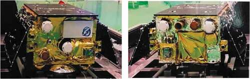
The WT01-A/B satellites were launched on 5 June 2019, with a Long March-11 solid-propellant carrier rocket based on a sea-based platform in the Yellow Sea area of China. The twin WT01 satellites fly in sun-synchronous orbits with an inclination of 45°. The altitude of the WT01 satellites is 575 km and a separation of 200 km at the beginning of the mission. As two small experimental satellites, WT01-A/B satellites weigh about 63 and 67 kg, respectively. The appearances of the WT01-A/B satellites are shown in .
Figure 1. The WT01 twin satellites.
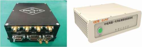
One of the primary objectives of the WT01 mission is to explore the LEO-based navigation augmentation technique. Both of the WT01 twin satellites are equipped with the navigation augmentation payload. Limited by satellite platform weight and space resources, the payload, with a dimension of 205 × 106 × 48 mm, net weight of 0.62 kg. The navigation augmentation payload is mainly composed of three subsystems, namely the navigation augmentation transmitting subsystem, the on-board GNSS receiving subsystem, and the main control subsystem. The navigation augmentation transmitting subsystem is responsible for transmitting the downlink navigation signals of the WT01 satellites. The on-board GNSS receiving subsystem receives the dual-frequency navigation signals of BDS and GPS. The main control subsystem in charge of real-time orbit determination, data management, clock training, and control management. The corresponding ground receiver was designed to receive the downlink navigation signals of the WT01 satellites, which can also recode the BDS and GPS observation. The navigation augmentation payload and the ground receiver are shown in . Both the navigation payload and the ground receiver can track GPS L1, L2 and BDS-2 B1I, B2I signals. The measurement data include pseudo-range, carrier phase, and Doppler observation. In addition, the ground receiver can receive Z1 and Z2 signals transmitted by WT01 satellites.
Figure 2. The navigation augmentation payload (left) and ground receiver (right) of the WT01 twin satellites.
3. Experiment setup and analysis methods
3.1. Data collection
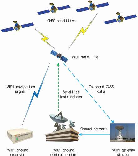
The WT01 satellites carry several payloads for communication, remote sensing, and navigation experiments. Due to the limitations of on-board resources, only one type of experiment can be conducted at a time. The data collection process of WT01 satellite is shown in . We first need to select an available time period to conduct navigation augmentation experiment. After we confirm the data collection period, the ground control center will send instructions to the satellite to set the working time of the navigation augmentation payload. Both of the WT01 twin satellites can track GPS/BDS navigation signals and store the observation data in the on-board memory. Then, the data is sent back to the gateway station through the satellite-ground data transmission link and recorded into the RINEX 3.0 files with 1 s sampling rate. The on-board GNSS observation on 8 June 2019 from 14:42:05 to 19:34:39 was collected during the communication experiments gap.
Figure 3. Schematic diagram of WT01 satellite data collection.
We conduct the data collection of WT01 downlink navigation signals with a ground tracking receiver installed in Shijiazhuang. We first calculated the transit period of WT01-A/B satellites with high elevation angle. The ground control center then generates instructions to set the working time and working mode of the navigation augmentation payload of WT01 satellites. The ground receiver is also switched on during the corresponding period to complete the data collection of WT01/GPS/BDS navigation signals. We carried out five experiments and collected downlink code and phase observation data of WT01 satellites with 1 s sampling interval. The duration of each tracking arc is about 5 minutes, and the specific data collection period is shown in . In the first three tracking arcs, the WT01-A satellite performs communication experiments in the corresponding period, so only the downlink navigation data of the WT01-B satellite is collected.
Table 1. Specific data collection period of the WT01A/B downlink navigation observation
3.2. Observation quality analysis method
There are two kinds of navigation observations evaluated in this paper, namely the on-board GNSS data and the LEO downlink navigation measurement. The observation equation of the on-board GNSS data can be expressed as follows:
where and
are the code and carrier phase observation between GNSS satellite
and LEO satellite
, respectively.
denotes the true geometric distance between the phase centers of the transmitting and receiving GNSS antennas.
is the speed of light,
and
are the clock offset of LEO and GNSS satellites, respectively.
denotes the ionospheric delay,
denotes relativistic delay,
and
are phase center offset corrections of LEO and GNSS satellites.
is the carrier phase ambiguity in the forms of integer multiples of the respective wavelength.
denotes the observation noise including multipath error. The code and phase observation equations of the WT01 downlink navigation signal are similar to the above formula, but it is the measurement between LEO and ground receiver, and there is an extra tropospheric delay error.
For the on-board GNSS data quality analysis, we first statistic the number of tracked GPS and BDS satellites and analyze the PDOP of GPS and BDS, respectively. Then, multipath errors of the on-board GPS/BDS dual-frequency measurements are investigated. Next, dynamic POD is performed based on the 3 h arc GPS observation. The POD accuracy is evaluated by using orbit overlap comparison. In terms of the WT01 downlink navigation measurements, we mainly focus on the multipath error and C/N0, and make a comparison with the GPS and BDS measurements recorded by the same ground receiver.
Multipath is an important indicator for observation quality evaluation. It is one of the main factors for signal distortion, which leads to the reduction of measurement accuracy (Montenbruck and Kroes Citation2003). In this paper, we calculate code multipath errors based on the multipath combinations used in TEQC software (Estey and Meerten Citation1999), which provide a direct measurement of dual-frequency code multipath errors. For dual-frequency code observation, the linear combination can be obtained as follows.
in which the ionospheric delay and geometry between satellite and receiver have been eliminated. Here subscripts 1 and 2 denote the different frequencies, and
are the multipath errors,
and
represent code observation noises,
and
denote the code and phase observation,
and
denote the combination of carrier phase ambiguity and differential code biases (DCB), which are constants throughout each pass of uninterrupted carrier phase tracking.
3.3. Dynamic POD principle
In this paper, we adopt dynamic POD method to evaluate the in-flight performance of WT01 satellite navigation payloads. In order to eliminate the ionospheric delay, we use the zero-difference ionosphere-free combination observations, which can be expressed as:
The motion equation of the satellite in the inertial system and its initial state can be described as follows (Peng and Wu Citation2009)
where is the position vector of the satellite’s center of mass.
is the sum of various conservative perturbations, including earth’s non-spherical gravitational perturbation, N-body perturbation, earth tide perturbation, ocean tide perturbation, earth rotation and deformation perturbation, general relativity perturbation.
is the non-conservative acceleration, which contains atmospheric drag perturbation, solar radiation pressure perturbation and earth radiation pressure perturbation.
is the empirical acceleration mainly includes linear and periodic RTN perturbations, used to deal with the model deficiencies of the classical dynamic orbit model.
Generally, the accurate initial state of the satellite, and
, cannot be known in advance, only their reference values,
and
, can be obtained. Then, we continuously optimize
and
through satellite observations to make them as close to the true value as possible, which is the task of POD.
It is defined as the state vector including position vector , velocity vector
and various dynamic parameters
to be estimated. Then the satellite motion equation and its initial state can be expressed as follows:
The observation equation is as belows:
where is the ith observation,
is the theoretical value calculation function at
time,
is the observation noise. Actually, the above formula is the nonlinear function of the observation, calculated value, and observation error. After linearization, the formula can be expressed as
where ,
is the state transition matrix.
If the following definitions are used:
Then the can be expressed as follows:
We use least square estimation to obtain the best solution is given by
Finally, using the optimal estimation value of the initial state and perturbation parameters, a smooth and continuous orbit can be obtained by orbit propagation.
3.4. POD strategy
In this paper, we investigate the short-arc dynamic POD performance of WT01 mission under the constraints of the communication service. A short arc length of 3 h observation between the communication service gaps is used for the POD process. The IGS final orbit and clock products are adopted. The POD model and strategy are summarized in .
Table 2. Dynamic POD model and strategy for WT01 mission
4. Results and analysis
4.1. On-board GNSS data quality analysis
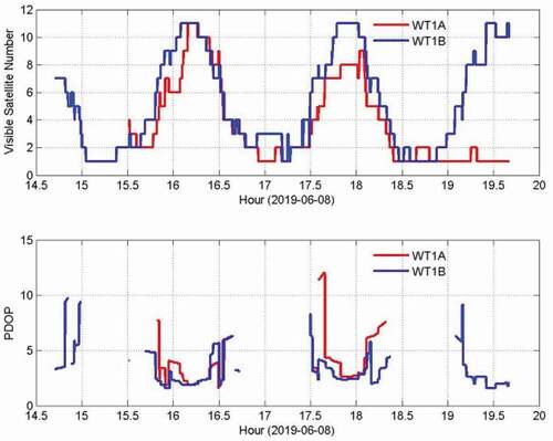
The on-board GNSS receivers of WT01 satellites have 12 channels for both GPS and BDS. In this section, we first analyze the visible satellite number and PDOP of GPS and BDS systems. As shown in , WT01-A/B satellites tracked 7.4 and 7.7 GPS satellites on average, and their average PDOP is 2.04 and 2.25, respectively. For the on-board BDS observation, the average tracking numbers of WT01 twin satellites are 3.8 and 5.2, and the mean PDOP is 4.10 and 3.26, respectively. It can be seen that the average tracking number of BDS is lower than that of GPS. This is because the WT01 satellites only track navigation signals from 14 BDS-2 satellites. The BDS-2 constellation consists of five Geosynchronous Earth Orbit (GEO), five Inclined Geosynchronous Satellite Orbit (IGSO), and four Medium Earth Orbit (MEO) satellites. The BDS PDOP is interrupted when the WT01 satellite moves outside the coverage range of the GEO and IGSO satellites.
Figure 4. The visible GPS satellite number (top) and PDOP (bottom) of the WT01 twin satellites.
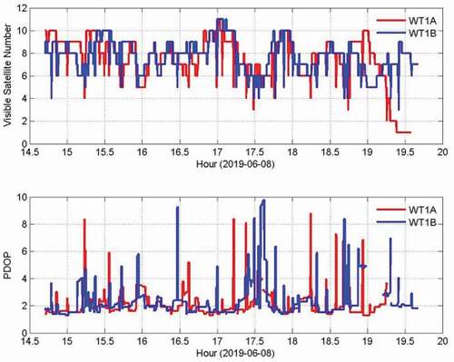
Figure 5. The visible BDS satellite number (top) and PDOP (bottom) of the WT01 twin satellites.
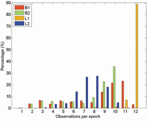
Although both WT01-A/B satellites have significant tracking numbers of GPS and BDS satellites, the data loss happened on L2 and B2 frequencies, especially for WT01-A satellites. We calculate the percentages of GPS and BDS dual-frequency measurement data of each observation epoch. As illustrated in , the histograms show the distribution of GNSS observation on each frequency. There are only 2.7 GPS and 1.1 BDS satellites are available for dual-frequency observation on average for the WT01-A satellite. For the WT01-B satellite, there are 7.1 GPS and 6.3 BDS satellites have complete dual-frequency measurement data record per epoch on average. The available dual-frequency observation data of the WT01-A satellite is significantly insufficient, which seriously affects the POD processing. Therefore, we only investigate the short-arc dynamic POD performance of the WT01-B satellite in the following section.
Figure 6. The statistics of the tracked satellites per epoch for BDS B1, B2 and GPS L1, L2 observation of WT01-A spaceborne GNSS receiver.
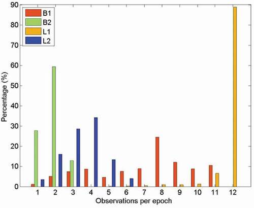
Figure 7. The statistics of the tracked satellites per epoch for BDS B1, B2 and GPS L1, L2 observation of WT01-B spaceborne GNSS receiver.
After investigating the observation distribution and integrity, we calculate and analyze the multipath error of WT01-A/B on-board GPS and BDS observation based on the multipath combination. shows the average multipath error of WT01-A/B satellites on-board GPS and BDS observation. The multipath errors of WT01-A on-board GPS L1, L2 and BDS B1, B2 observation are 0.51, 0.73, 0.63, and 0.57 m, respectively. For the WT01-B satellite, the multipath errors of GPS L1, L2 and BDS B1, B2 code observation are 0.57, 0.74, 0.66, and 0.59 m, respectively. The multipath error series of GPS/BDS four-frequency signals are shown in with respect to elevation angle. It should be noted that the on-board BDS multipath errors show some trend variations, which need further investigation.
Figure 8. The multipath errors for GPS L1 (left) and L2 (right) of the WT01-A (top) and WT01-B (bottom) satellites.
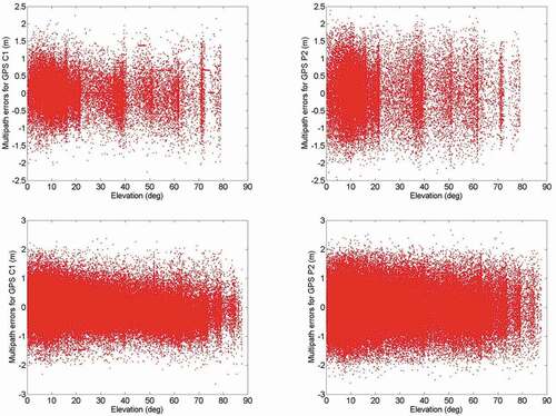
Figure 9. The multipath errors for BDS B1 (left) and B2 (right) of the WT01-A (top) and WT01-B (bottom) satellites.
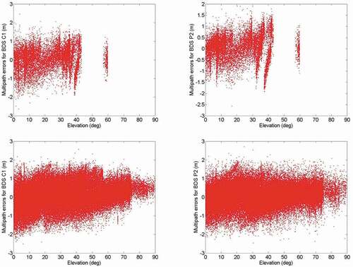
Table 3. The mean multipath errors for on-board GPS and BDS observation (unit: m)
4.2. Short-arc dynamic POD
The POD accuracy is an important indicator to evaluate the data quality of LEO on-board GNSS observation. Restricted by the priority of the navigation augmentation payload on the communication satellite, the on-board GNSS data between the communication experiments gap was collected. The bad quality data at the head and end of the collection period was removed, and a total of 4 hours of on-board GNSS data from 14:53:00 to 18:53:00 was used to perform POD accuracy analysis. Due to the short duration of observation data, the performance of short arc dynamic POD of WT01 satellite is evaluated.
We adopted orbit overlap comparison to evaluate the POD precision, which is a common method for orbit accuracy validation in the absence of satellite precise orbit. As illustrated in , between two consecutive 3 h arcs, there is a 1 h overlap period. We take the Root Mean Square (RMS) of overlapping orbital difference time series as POD precision.
Figure 10. Orbit overlap zone diagram.
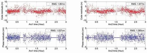
The dynamic POD is conducted on WT01-B satellite based on two 3 h arc on-board GPS observations. The orbit overlap comparison result shows that the orbit determination accuracy of WT01-B satellite is 7.1 cm, in which the accuracy of R, T, and N directions are 2.1, 4.2, and 5.3 cm, respectively. shows the error bar of the orbit overlapping precision of the WT01-B satellite. The mean orbit difference of R, T, N, and 3D directions are 0.4, 0.8, 0.5, and 7.0 cm, respectively. Since the mean value of the orbital error in the R, T, and N directions is very small, its standard deviation in each direction is very close to the RMS of the orbit overlapping error. The standard deviation of 3D direction is 1.3 cm, which indicates that the orbital position accuracy is relatively stable. The orbit determination code residuals of the two arcs are 1.85 and 1.98 m, and the carrier phase residuals are 1.0 and 1.1 cm, respectively. The time series of POD residuals are shown in , in which we can see that some of the observation data is not available in the POD process. This may be caused by the on-board resources occupied by other services in the corresponding period, which leads to the interruption or abnormality of on-board GNSS data receiving. In general, the orbit determination code and carrier phase residuals of the WT01-B satellite are at a normal level.
Figure 11. Error bar of the orbit overlapping precision in R, T, N, and 3D direction of the WT01-B satellite.
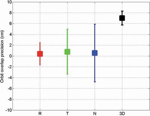
Figure 12. Code and phase residuals of WT01-B satellite short-arc POD.
4.3. Downlink navigation data quality analysis
In this section, we mainly analyze the characteristics of multipath error and C/N0 of WT01 downlink navigation signals. Five groups of WT01 Z1/Z2 and GPS/BDS experiment data recoded by the same ground receiver were analyzed and compared. Multipath error can reflect the system error and noise level of navigation signal to a certain extent, which is an important indicator to verify whether the LEO navigation signal can provide navigation service. The multipath error evaluation results of WT01-A/B downlink navigation signals and traditional GNSS navigation signals are summarized as follows. presents an example of the multipath error time series of WT01-A/B satellites on 13 July 2019. The multipath error values of each arc are statistics and summarized in . The average multipath errors of Z1 and Z2 observations are 0.81 and 0.80 m, respectively. The mean multipath errors of GPS L1, L2 and BDS B1, B2 observation are 0.66, 0.52, 0.65, and 0.58 m, respectively, as shown in . Experimental results reveal that the multipath errors of WT01 downlink navigation signals are slightly larger than that of GNSS but at the same order of magnitude.
Figure 13. The multipath errors for Z1 (left) and Z2 (right) navigation signals of WT01-A (top) and WT01-B (bottom) satellites.
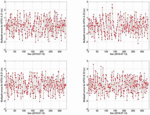
Figure 14. The average multipath errors of Z1, Z2, L1, L2, B1, and B2 frequencies.
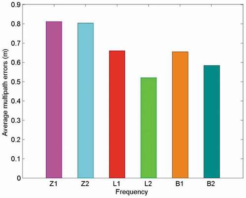
Table 4. The multipath errors for WT01-A/B, GPS, and BDS downlink navigation observation (unit: m)
C/N0 is an important technical parameter that affects navigation signal searching, tracking, and positioning. Owing to the advantages of the low orbital altitude, strong signal power, and low signal space free loss, the C/N0 of LEO navigation signal is theoretically higher than that of GNSS signals. This is also an important reason why some scholars hope that it can enhance GNSS navigation and positioning services in urban canyons and indoor areas. Therefore, we analyzed the distribution and variation characteristics of the C/N0 of WT01 downlink navigation signals, and compared it with that of GNSS signals. show an example of C/N0 variations of WT01, GPS, and BDS signal on 13 July 2019. In this visible observation arc, the WT01 C/N0 values vary from 36.7 dB/Hz to 60.0 dB/Hz, while the minimum and maximum C/N0 values are 18.6 dB/Hz, 54.5 dB/Hz for GPS, and 25.1 dB/Hz, 52.9 dB/Hz for BDS, respectively. The results show that WT01 navigation signals are much stronger than GNSS signals, which may provide a solution to the PNT service of indoor areas in the future. The C/N0 variations of five experimental arcs are summarized in .
Figure 15. The C/N0 of WT01-A (left) and WT01-B (right) navigation signals on 13 July 2019.
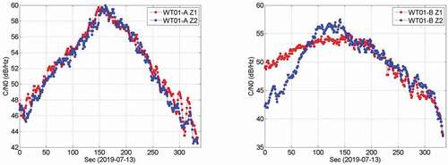
Figure 16. The C/N0 of GPS L1 (green), L2 (black) and BDS B1 (cyan), B2 (magenta) navigation signals on 13 July 2019.
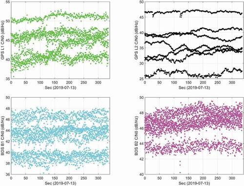
Table 5. The C/N0 range of WT01-A/B, GPS, and BDS downlink navigation observation (unit: dB/Hz)
5. Discussion
In this experiment, the quality of onboard GPS/BDS observation and downlink navigation data of WT01-A/B satellites was evaluated, and the short-arc dynamic POD performance was also verified. The results indicate centimeter-level orbit precision is achievable, although the onboard GNSS data quality still can be improved. The downlink navigation signals transmitted by the WT01 satellite have similar characteristics to the GNSS signals, and it has a higher C/N0 than the GNSS signal, which further verifies that the navigation signal of the LEO communication satellite can meet the basic requirement of navigation augmentation research.
The navigation payload on WT01-A/B satellites proves the feasibility of navigation augmentation service based on the LEO communication constellation. With the deep integration of communication and navigation technology, the performance of the LEO navigation payload can be further improved. In the future, the constellation providing LEO navigation augmentation service is likely to be a hybrid constellation of multi-functional satellites such as communications and remote sensing. Therefore, the design of the navigation augmentation payload should consider compatibility and collaboration with other modules. As the number of LEO satellites increases, new LEO navigation augmentation ideas and LEO positioning technologies will be inspired, which will further improve the future PNT capacity.
6. Conclusions
In this paper, we mainly investigated the in-flight performance of navigation augmentation payload on WT01 communication satellites. The data quality of on-board GNSS and WT01 downlink navigation observations was analyzed. The dynamic POD performance based on short-arc on-board data was investigated. The main conclusions are as follows.
The WT01 on-board GNSS receivers can track 7.6 GPS and 4.5 BDS satellites on average and their PDOP are 2.15 and 3.68, respectively. Unfortunately, there are data loss happening at L2 and B2 frequencies, especially for the WT01-A satellite.
The average multipath errors of the WT01 on-board GPS L1, L2 and BDS B1, B2 code observation are 0.54, 0.74, 0.65, and 0.58 m, respectively. However, the on-board BDS multipath errors show some trend variations, which need further investigation.
The overlap comparison results show that the short-arc dynamic POD process can obtain centimeter-level orbit solution. The orbit overlapping accuracy of R, T, N, and 3D directions are 2.1, 4.2, 5.3, and 7.1 cm, respectively.
The average multipath errors of Z1 and Z2 observation are 0.81 and 0.80 m, respectively, which are slightly larger than that of GNSS, but at the same order of magnitude. The maximum C/N0 value of the WT01 navigation signal can reach 60 dB Hz, which reveals much stronger than GNSS, which means the navigation signals of LEO satellites meet the basic conditions of navigation augmentation and may provide a solution to the PNT service of indoor areas in the future.
As further attention is paid to the integration of communication and navigation technology, we hope that the LEO communication satellites can leave as much space and source as possible for the navigation payloads. This will offer more accurate and more reliable space position information to support the operation, control, and adjustment of the LEO constellation. And it will provide more solid experiment conditions for the LEO-based GNSS augmentation research.
Acknowledgments
The IGS analysis centers are greatly acknowledged for providing the GNSS products. Furthermore, the authors are grateful for the comments and remarks of the reviewers and editors, which helped to improve the manuscript.
Disclosure statement
No potential conflict of interest was reported by the authors.
Data availability statement
The data that support the findings of this study are available from the corresponding author, upon reasonable request.
Additional information
Funding
Notes on contributors
Ziqian Wu
Ziqian Wu is a postdoc in State Key Laboratory of Satellite Navigation System and Equipment Technology. His research interests include satellite precise orbit determination, satellite clock evaluation, and LEO-based navigation augmentation technology. He holds PhD in Astrometry and Astromechanics from the Shanghai Astronomical Observatory, Chinese Academy of Sciences.
Baoguo Yu
Baoguo Yu is the Director of State Key Laboratory of Satellite Navigation System and Equipment Technology. His research interests include satellite measurement and control, communication and navigation integration and indoor positioning. He holds PhD in Communication and Information System from the Beijing Institute of Technology, China.
Chuanzhen Sheng
Chuanzhen Sheng is a Senior Engineer in State Key Laboratory of Satellite Navigation System and Equipment Technology. His research interests include Multi-source fusion positioning, satellite orbit determination and GNSS deformation. He obtained his Ph.D. from the China Earthquake Administration.
Jingkui Zhang
Jingkui Zhang is a Senior Engineer in State Key Laboratory of Satellite Navigation System and Equipment Technology and a PhD candidate in the China University of Mining and technology. His research interests include PPP-RTK and GNSS time transfer.
Song Xie
Song Xie is a Senior Engineer in State Key Laboratory of Satellite Navigation System and Equipment Technology. His research interests include navigation augmentation payload and ground monitoring receiver design.
Cailun Wu
Cailun Wu is the Deputy director of the State Key Laboratory of Satellite Navigation System and Equipment Technology. His research interests include navigation signal design and LEO navigation system design. He obtained his Ph.D. from the Tsinghua University, China.
References
- Barlier, F., C. Berger, J.L. Falin, G. Kockarts, and G. Thuillier. 1978. “A Thermospheric Model Based on Satellite Drag Data.” Annales de Geophysique 34: 9–24.
- Belabbas, B., P. Rémi, and M. Meurer. 2008. “Performance Assessment of GBAS CAT III Using GPS and Galileo.” In Proceedings of the 21st International Technical Meeting of the Satellite Division of the Institute of Navigation (ION GNSS 2008), 2945–2952. Savannah, GA, September 2008.
- Bock, H., A. Jäggi, G. Beutler, and U. Meyer. 2014. “GOCE: Precise Orbit Determination for the Entire Mission.” Journal of Geodesy 88 (11): 1047–1060. doi:https://doi.org/10.1007/s00190-014-0742-8.
- Cai, C., Y. Gao, L. Pan, and J. Zhu. 2015. “Precise Point Positioning with Quad-Constellations: GPS, BeiDou, GLONASS and Galileo.” Advances in Space Research 56 (1): 133–143. doi:https://doi.org/10.1016/j.asr.2015.04.001.
- Erol, S.R.M.A., İ.M. Ozulu, and V. Ilçi. 2021. “Impact of Different Sampling Rates on Precise Point Positioning Performance Using Online Processing Service.” Geo-spatial Information Science 24 (2): 302–312. doi:https://doi.org/10.1080/10095020.2020.1842811.
- Estey, L.H., and C.M. Meerten. 1999. “TEQC: The Multi-Purpose Toolkit for GPS/GLONASS Data.” GPS Solutions 3 (1): 42–49. doi:https://doi.org/10.1007/PL00012778.
- Folkner, W.M., J.G. Williams, and D.H. Boggs. 2009. “The Planetary and Lunar Ephemeris DE 421.” The Interplanetary Network Progress Report 42: 178.
- Ge, H., B. Li, M. Ge, N. Zang, L. Nie, Y. Shen, and H. Schuh. 2018. “Initial Assessment of Precise Point Positioning with LEO Enhanced Global Navigation Satellite Systems (Legnss).” Remote Sensing 10 (7): 984. doi:https://doi.org/10.3390/rs10070984.
- Geng, J., C. Shi, Q. Zhao, and J. Liu. 2007. “GPS Precision Orbit Determination from Combined Ground and Space-borne Data.” Geomatics and Information Science of Wuhan University 32 (10): 906–909. doi:https://doi.org/10.3969/j.1671-8860.2007.10.016.
- Gu, D., Y. Liu, B. Yi, J. Cao, and X. Li. 2017. “In-flight Performance Analysis of MEMS GPS Receiver and Its Application to Precise Orbit Determination of APOD-A Satellite.” Advances in Space Research 60 (12): 2723–2732. doi:https://doi.org/10.1016/j.asr.2017.08.023.
- Hao, M., J. Zhang, R. Niu, C. Deng, and H. Liang. 2018. “Application of BeiDou Navigation Satellite System in Emergency Rescue of Natural Hazards: A Case Study for Field Geological Survey of Qinghai−Tibet Plateau.” Geo-spatial Information Science 21 (4): 294–301. doi:https://doi.org/10.1080/10095020.2018.1522085.
- Joerger, M., L. Gratton, B. Pervan, and C.E. Cohen. 2010. “Analysis of Iridium-Augmented GPS for Floating Carrier Phase Positioning.” Navigation 57 (2): 137–160. doi:https://doi.org/10.1002/j.2161-4296.2010.tb01773.x.
- Kang, Z., B. Tapley, S. Bettadpur, J. Ries, P. Nagel, and R. Pastor. 2006. “Precise Orbit Determination for the GRACE Mission Using Only GPS Data.” Journal of Geodesy 80 (6): 322–331. doi:https://doi.org/10.1007/s00190-006-0073-5.
- Ke, M., J. Lv, J. Chang, W. Dai, K. Tong, and M. Zhu. 2015. “Integrating GPS and LEO to Accelerate Convergence Time of Precise Point Positioning.” In Proc. Of 2015 International Conference on Wireless Communications & Signal Processing (WCSP), 1–5. Nanjing, China, 15–17 Oct. 2015. doi:https://doi.org/10.1109/WCSP.2015.7341230.
- Larson, K.M., and F.G. Nievinski. 2013. “GPS Snow Sensing: Results from the EarthScope Plate Boundary Observatory.” GPS Solutions 17 (1): 41–52. doi:https://doi.org/10.1007/s10291-012-0259-7.
- Larson, K.M., E.E. Small, E. Gutmann, A. Bilich, P. Axelrad, and J. Braun. 2008. “Using GPS Multipath to Measure Soil Moisture Fluctuations: Initial Results.” GPS Solutions 12 (3): 173–177. doi:https://doi.org/10.1007/s10291-007-0076-6.
- Li, B., H. Ge, M. Ge, L. Nie, Y. Shen, and H. Schuh. 2019a. “LEO Enhanced Global Navigation Satellite System (Legnss) for Real-time Precise Positioning Services.” Advances in Space Research 63 (1): 73–93. doi:https://doi.org/10.1016/j.asr.2018.08.017.
- Li, K., X. Zhou, W. Wang, Y. Gao, G. Zhao, E. Tao, and K. Xu. 2018. “Centimeter-level Orbit Determination for TG02 Spacelab Using On-board GNSS Data.” Sensors 18 (8): 2671. doi:https://doi.org/10.3390/s18082671.
- Li, X., H. Lv, F. Ma, X. Li, J. Liu, and Z. Jiang. 2019c. “GNSS RTK Positioning Augmented with Large LEO Constellation.” Remote Sensing 11 (3): 228. doi:https://doi.org/10.3390/rs11030228.
- Li, X., F. Ma, X. Li, H. Lv, L. Bian, Z. Jiang, and X. Zhang. 2019b. “LEO Constellation-Augmented Multi-GNSS for Rapid PPP Convergence.” Journal of Geodesy 93 (5): 749–764. doi:https://doi.org/10.1007/s00190-018-1195-2.
- Liu, X., and L. Zhang. 2019. “Analysis of Iridium-Augmented GPS Positioning Performance.” The Journal of Engineering 2019 (3). doi:https://doi.org/10.1049/joe.2019.0533.
- Lyard, F., F. Lefevre, T. Letellier, and O. Francis. 2006. “Modelling the Global Ocean Tides: Moden Insights from FES2004.” Ocean Dynamics 56: 394–415. doi:https://doi.org/10.1007/s10236-006-0086-x.
- Maine, K., C. Devieux, and P. Swan. 1995. “Overview of IRIDIUM Satellite Network.” Proceedings of WESCON’ 95: 483–490. doi:https://doi.org/10.1109/WESCON.1995.485428.
- Montenbruck, O., S. Hackel, J. van Den Ijssel, and D. Arnold. 2018. “Reduced Dynamic and Kinematic Precise Orbit Determination for the Swarm Mission from 4 Years of GPS Tracking.” GPS Solutions 22 (3): 79. doi:https://doi.org/10.1007/s10291-018-0746-6.
- Montenbruck, O., and R. Kroes. 2003. “In-flight Performance Analysis of the CHAMP BlackJack GPS Receiver.” GPS Solutions 7 (2): 74–86. doi:https://doi.org/10.1007/s10291-003-0055-5.
- Montenbruck, O., P. Steigenberger, and A. Hauschild. 2020. “Comparing the ‘Big 4ʹ - A User’s View on GNSS Performance.” In Proc. Of 2020 IEEE/ION Position, Location and Navigation Symposium (PLANS), 407–418. Portland, OR, USA, 20–23 Apirl 2020. doi:https://doi.org/10.1109/PLANS46316.2020.9110208.
- Peng, D., and B. Wu. 2009. “Precise Orbit Determination for Jason-1 Satellite Using On-board GPS Data with Cm-level Accuracy.” Chinese Science Bulletin 54 (2): 196–202. doi:https://doi.org/10.1007/s11434-008-0513-0.
- Peter, H., A. Jäggi, J. Fernández, D. Escobar, F. Ayuga, D. Arnold, M. Wermuth, et al. 2017. “Sentinel-1A - First Precise Orbit Determination Results.” Advances in Space Research 60 (5): 879–892. doi:https://doi.org/10.1016/j.asr.2017.05.034.
- Petit, G., and B. Luzum. 2010. “IERS Conventions 2010.” IERS Technical Note. Germany.
- Pratt, J., P. Axelrad, K.M. Larson, B. Lesage, R. Gerren, and N. DiOrio. 2013. “Satellite Clock Bias Estimation for iGPS.” GPS Solutions 17 (3): 381–389. doi:https://doi.org/10.1007/s10291-012-0286-4.
- Reid, T.G.R., A.M. Neish, T. Walter, and P.K. Enge. 2018. “Broadband LEO Constellations for Navigation.” Navigation 65 (2): 205–220. doi:https://doi.org/10.1002/navi.234.
- Rim, H. 1992. “TOPEX Orbit Determination Using GPS Tracking System.” Ph.D. thesis, Texas University, Austin, USA.
- Schutz, B.E., B.D. Tapley, P.A.M. Abusali, and H.-J. Rim. 1994. “Dynamic Orbit Determination Using GPS Measurements from TOPEX/POSEIDON.” Geophysical Research Letters 21 (19): 2179–2182. doi:https://doi.org/10.1029/94gl01040.
- Su, M., X. Su, Q. Zhao, and J. Liu. 2019. “BeiDou Augmented Navigation from Low Earth Orbit Satellites.” Sensors 19 (1): 198. doi:https://doi.org/10.3390/s19010198.
- Švehla, D., and M. Rothacher. 2003. “Kinematic and Reduced-Dynamic Precise Orbit Determination of Low Earth Orbiters.” Advances in Geosciences 1: 47–56. doi:https://doi.org/10.5194/adgeo-1-47-2003.
- Tapley, B., J. Ries, S. Bettadpur, D. Chambers, M. Cheng, F. Condi, and S. Poole. 2007. “The GGM03 Mean Earth Gravity Model from GRACE.” In AGU Fall Meeting, G42A–03.
- Tian, S., W. Dai, R. Liu, J. Chang, and G. Li. 2014. “System Using Hybrid LEO-GPS Satellites for Rapid Resolution of Integer Cycle Ambiguities.” IEEE Transactions on Aerospace and Electronic Systems 50 (3): 1774–1785. doi:https://doi.org/10.1109/TAES.2014.120662.
- Walter, T. 2017. “Satellite Based Augmentation Systems.” In Springer Handbook of Global Navigation Satellite Systems. Springer Handbooks, edited by P. J. G. Teunissen and O. Montenbruck, 339–361. Cham, Switzerland: Springer. doi:https://doi.org/10.1007/978-3-319-42928-1_12.
- Wang, L., R. Chen, D. Li, B. Yu, and C. Wu. 2018b. “Quality Assessment of the LEO Navigation Augmentation Signals from Luojia-1A Satellite.” Geomatics and Information Science of Wuhan University 43 (12): 2191–2196. doi:https://doi.org/10.13203/j.whugis20180413.
- Wang, L., R. Chen, D. Li, G. Zhang, X. Shen, B. Yu, C. Wu, et al. 2018a. “Initial Assessment of the LEO Based Navigation Signal Augmentation System from Luojia-1A Satellite.” Sensors 18 (11): 3919. doi:https://doi.org/10.3390/s18113919.
- Wang, L., R. Chen, B. Xu, X. Zhang, T. Li, and C. Wu. 2019. “The Challenges of LEO Based Navigation Augmentation System Lessons Learned from Luojia-1A Satellite.” In China Satellite Navigation Conference (CSNC) 2019 Proceedings, 298–310. doi:https://doi.org/10.1007/978-981-13-7759-4_27.
- Wang, L., B. Xu, W. Fu, R. Chen, T. Li, Y. Han, and H. Zhou. 2020. “Centimeter-Level Precise Orbit Determination for the Luojia-1A Satellite Using BeiDou Observations.” Remote Sensing 12 (12): 2063. doi:https://doi.org/10.3390/rs12122063.
- Wu, S.C., T.P. Yunck, and C.L. Thornton. 1991. “Reduced-Dynamic Technique for Precise Orbit Determination of Low Earth Satellites.” Journal of Guidance, Control, and Dynamics 14 (1): 24–30. doi:https://doi.org/10.2514/3.20600.
- Yang, Y., W. Gao, S. Guo, Y. Mao, and Y. Yang. 2019. “Introduction to BeiDou-3 Navigation Satellite System.” Navigation 66 (1): 7–18. doi:https://doi.org/10.1002/navi.291.
- Yang, Y., Y. Mao, and B. Sun. 2020. “Basic Performance and Future Developments of BeiDou Global Navigation Satellite System.” Satellite Navigation 1 (1). doi:https://doi.org/10.1186/s43020-019-0006-0.
- Zhang, X., and F. Ma. 2019. “Review of the Development of LEO Navigation-Augmented GNSS.” Acta Geodaetica et Cartographica Sinica 48 (9): 1073–1087. doi:https://doi.org/10.11947/j.AGCS.2019.20190176.
- Zhao, Q., C. Wang, J. Guo, G. Yang, M. Liao, H. Ma, and J. Liu. 2017. “Enhanced Orbit Determination for BeiDou Satellites with FengYun-3C Onboard GNSS Data.” GPS Solutions 21 (3): 1179–1190. doi:https://doi.org/10.1007/s10291-017-0604-y.
- Zhou, X., X. Wang, G. Zhao, H. Peng, and B. Wu. 2015. “The Precise Orbit Determination for HY2A Satellite Using GPS, DORIS and SLR Data.” Geomatics and Information Science of Wuhan University 40 (8): 1000–1005. doi:https://doi.org/10.13203/j.whugis20130730.