
 ?Mathematical formulae have been encoded as MathML and are displayed in this HTML version using MathJax in order to improve their display. Uncheck the box to turn MathJax off. This feature requires Javascript. Click on a formula to zoom.
ABSTRACT
The indoor positioning system is now an important technique as part of the Internet-of-Things (IoT) ecosystem. Among indoor positioning techniques, multiple Wi-Fi Access Points (APs)-based positioning systems have been researched a lot. There is a lack of research focusing on the scene where only one Wi-Fi AP is available. This work proposes a hybrid indoor positioning system that takes advantage of the Fine-Timing Measurements (FTM) technique that is part of the IEEE 802.11mc standard, introduced back in 2016. The system uses one single Wi-Fi FTM AP and takes advantage of the built-in inertial sensors of the smartphone to estimate the device’s position. We explore both Loosely Coupled (LC) and Tightly Coupled (TC) integration schemes for the sensors’ data fusion. Experimental results show that the proposed methods can achieve an average positioning accuracy of about 1 m without knowing the initial position. Compared with the LC integration method, the median error accuracy of the proposed TC fusion algorithm has improved by more than 52% and 67%, respectively, in the two experiments we set up.
1. Introduction
Location information is now an indispensable part of our lives, especially with the advent of the Internet of Things (IoT) era, the demands for Location-Based Services (LBS) will become more and more extensive. Outdoors, the Global Navigation Satellite System (GNSS) (Ge et al. Citation2022) can provide relatively accurate and long-term positioning. However, in places where GNSS signals are blocked, such as under dense buildings, indoor environments, etc., the accuracy of GNSS positioning will rapidly decrease (Li et al. Citation2019). Therefore, positioning techniques for GNSS-blocked scenarios have received widespread attention. So far, a variety of indoor positioning techniques based on different sources or sensors have been proposed and can be classified into two types: 1) building independent such as image-based technologies (Li et al. Citation2021) and Inertial Measurement Unit (IMU)-based dead reckoning (Wu et al. Citation2019b) and 2) building dependent, which can be further classified as 1) building’s infrastructures utilized (such as Wi-Fi (Al-Qaness Citation2019), cellular (Dalla Torre et al. Citation2019), and Bluetooth (Cao et al. Citation2019), and 2) dedicated infrastructures required (such as Ultra-Wide-Band (UWB) (Tian, Wang, and Salcic Citation2019), Radio Frequency Identification (RFID) (Ruiz et al. Citation2012), ultrasonic (Mannay et al. Citation2021), acoustic (Chen et al. Citation2021), etc.). The commonly used solutions for mobile phones are Wi-Fi, Bluetooth, and IMU positioning. The Wi-Fi or Bluetooth positioning is usually able to estimate the absolute positions, and its positioning errors will not accumulate with the increase of time, while the estimated positions are relatively discrete and affected by Non-Line-Of-Sight (NLOS), signal coverage of Access Point (AP), and multipath problems (Gu et al. Citation2019a). The Wi-Fi positioning usually has three implementation schemes, namely Received-Signal-Strength-Indicator (RSSI) ranging (Zhuang and El-Sheimy Citation2016), Round-Trip Time (RTT) ranging (Dvorecki et al. Citation2019), and fingerprint positioning (Chen et al. Citation2014). The IMU positioning can only estimate the relative position to a known starting point, while the estimated position is relatively continuous and does not depend on any specific signal coverage. The error in a short period is small but will increase rapidly with time accumulation (Lu et al. Citation2018). The IMU positioning is usually implemented in two ways, namely Pedestrian Dead Reckoning (PDR) (step length and heading estimation) and Inertial Navigation System (INS) (integration of gyro and accelerometer data) (Harle Citation2013).
The above analysis shows that Wi-Fi and IMU complement each other in positioning. Thus, the positioning of Wi-Fi and IMU fusion can compensate for their corresponding shortcomings. However, the current positioning schemes of Wi-Fi and PDR fusion still have some problems. First, the establishment and maintenance of the Wi-Fi fingerprint database are laborious (Zhang et al. Citation2018). Moreover, the latest generation of Android systems limits the frequency of Wi-Fi scanning, which limits the use of fingerprint-based positioning. Second, the accuracy of RSSI-based ranging decreases rapidly when the distance gets large, and the environmental variation also affects the RSSI value, resulting in a decrease in accuracy (Li et al. Citation2021). Third, the current Wi-Fi positioning solutions usually require multiple Wi-Fi APs to determine the location of a target (Chen and Chen Citation2021). It is difficult to achieve in some actual situations because one Wi-Fi base station is enough for internet communication in an indoor room. Moreover, the Wi-Fi signals from other rooms suffer from serious NLOS and multipath problems.
Regarding the first problem, some other solutions, e.g. ranging-based methods, have been explored for alternatives (Zafari, Gkelias, and Leung Citation2019). For the second problem, currently, IEEE 802.11–2016 has standardized the Wi-Fi Fine-Time Measurement (FTM) protocol, which can provide meter-level ranging accuracy according to the Wi-Fi Alliance (Yu et al. Citation2020b). The accuracy of RTT ranging will not change significantly with the increase of distance, which makes up for the problem of RSSI ranging to a certain extent (Yu et al. Citation2020b). Therefore, the fusion of RTT and RSSI will improve the positioning accuracy in theory. The third problem shows that studying the positioning scheme under one single Wi-Fi AP will alleviate the strong dependence on multiple Wi-Fi APs, to achieve positioning without increasing the cost. Moreover, most of the current fusion positioning methods based on Wi-Fi and IMU fusion are Loosely Coupled (LC) schemes. The target parameters are estimated separately, and then the estimated results are fused. But not Tightly Coupled (TC) solutions, the sensor data are put together to jointly optimize the model parameters of each sensor. Studies have shown that the TC scheme has higher accuracy than LC (Sun et al. Citation2020; Zhuang and El-Sheimy Citation2016). However, as far as we know, few works have been proposed for a TC positioning scheme that integrates RTT ranging, RSSI ranging, and IMU positioning. Therefore, this article proposes an enhanced TC positioning scheme based on the integration of Wi-Fi RTT, RSSI, and PDR. The main contributions of this article are threefold as follows.
Extended Kalman Filter (EKF) based LC and TC integration algorithms are proposed, respectively, for real-time indoor positioning by fusing PDR and one single Wi-Fi AP ranging. Especially, our proposed TC scheme models PDR error, Wi-Fi RSSI ranging error, and FTM ranging error together to estimate location.
A nonlinear-least-squares-based algorithm is proposed to estimate the absolute initial position by combining PDR with both RSSI and RTT measurements from one single Wi-Fi FTM AP. This proposal solves the requirement that at least three APs are required for absolute positioning.
The effect of using one single Wi-Fi FTM AP to suppress PDR drift for long-term localization and the improvement of the proposed TC algorithm compared to the LC algorithm is evaluated. The experimental result proves that our proposed system realizes a similar absolute localization accuracy to multi-FTM APs based systems.
The remainder of this paper is organized as follows: Section 2 introduces the related works. Section 3 introduces the smartphone-based PDR algorithm. Section 4 details the proposed integration methods of PDR and Wi-Fi Ranging. Section 5 introduces the proposed method to determine the initial position. Section 6 describes the experimental results of the proposed algorithm. Finally, Section 7 concludes this article.
2. Related work
In this section, we introduce and discuss the existing works related to this paper to give an overview of the current research state. First, we present existing works of dead reckoning based on built-in inertial sensors. Then, the research state of Wi-Fi-based positioning is summarized. Finally, we introduce the related works of PDR and Wi-Fi fusion positioning systems.
2.1. Indoor positioning based on built-in inertial sensors
Built-in inertial sensors-based indoor positioning systems usually have two implementation methods, namely PDR (step length and heading accumulation) and INS (integration of gyro and accumulator data).
In traditional PDR systems, step detection, step length, and heading estimation are three indispensable components. For step detection, various algorithms have been proposed in recent years, such as peak detection (Gu et al. Citation2019b; Kang and Han Citation2015), pitch angle detection (Poulose, Eyobu, and Han Citation2019), Signal Vector Magnitude (SVM) (Hsu, Wang, and Chang Citation2017), and decision tree model (Wu et al. Citation2019a). The mathematical models are usually designed for step length estimation. In recent years, some machine learning-based step length estimators have been proposed, such as stacked autoencoders (Gu et al. Citation2019a), Artificial Neural Networks (ANN) (Xu et al. Citation2019), etc. Wu et al. (Citation2019b) summarized the most commonly used step detection and step length estimation models. Heading can be estimated by integrating the gyroscope data. To constrain the drift of the gyroscope, the magnetometer is usually fused. Acceleration data can also be used for heading estimation, such as the Fast Fourier Transform (FFT) based method (Liu et al. Citation2016) and Principal Component Analysis (PCA) based method (Qian et al. Citation2015), but it is not often used in smartphone-based positioning scenarios where the measured horizontal acceleration from walking motion is weak and easily disturbed by lateral acceleration resulting the main acceleration direction may not consist with the walking direction.
The INS system has higher requirements for hardware; otherwise, its data integration errors will accumulate rapidly. For low-cost hardware, the Zero-Velocity Update Technique (ZUPT) is commonly used to constrain the error drift (Bai et al. Citation2020). However, for handheld devices, there is no obvious zero velocity phase during walking, hence the INS is fused with PDR for drift constraint (Zhuang and El-Sheimy Citation2016).
2.2. Wi-Fi-based indoor positioning
The commonly used Wi-Fi positioning can be divided into fingerprint-based and ranging-based methods.
The fingerprint-based method is usually divided into two stages: the training stage and the testing stage. In the training phase, the Wi-Fi RSSI characteristics on each point of the positioning area are collected to form a Wi-Fi fingerprint database. In the testing phase, the Wi-Fi RSSI characteristics collected online are used to match the trained Wi-Fi fingerprint to obtain the online position. The matching algorithms mainly include K-nearest Neighbor (KNN), K-weighted Nearest Neighbor (WKNN), SVM, and ANN models. The KNN/WKNN (Li, Zhang, and Li Citation2016; Luo and Hsiao Citation2019) models are the simplest deterministic methods, and Poulose and Han (Citation2020) compared their performance. The fingerprints with higher matching scores in the database are used to determine the user’s location. The SVM-based method directly maps RSSI measurements to locations through nonlinear regression by supervised learning technique (Luo and Hsiao Citation2019). The ANN-based methods estimate location by training an ANN model to directly process the input RSSI value into position. Recently, several ANN-based solutions, such as Multilayer Neural Network (MLNN) (Dai, Ying, and Xu Citation2016.), Generative Adversarial Network (GAN) (Seong and Seo Citation2020), and Recurrent Neuron Network (RNN) (Hoang et al. Citation2019), have been proposed.
There are two schemes for Wi-Fi ranging-based methods. The first one uses a Wi-Fi RSSI attenuation model to calculate the distance between mobile devices and Wi-Fi APs (Correa et al. Citation2016). The second one is a Time of Flight (ToF) based ranging, which is only used for devices that support the Wi-Fi FTM protocol (Banin et al. Citation2019; Bullmann et al. Citation2020; Ma et al. Citation2020). Bullmann et al. (Citation2020) compared the two ranging-based methods in realistic scenarios, and their results show that, although FTM ranging achieves smaller positioning errors compared to RSSI ranging, its error behavior (caused by NLOS and multipath propagation) is similar to RSSI. To enhance the accuracy, Si et al. (Citation2020) proposed a Gaussian model to identify Line-of-Sight (LOS)/NLOS and used the Least Square (LS) algorithm to infer the location. Yu et al. (Citation2020b) analyzed the main factors that affect the accuracy of Wi-Fi FTM ranging and proposed the corresponding calibrating, filtering, and modeling algorithms that can effectively reduce the ranging error caused by clock deviation, NLOS, and multipath propagation. Because of NLOS and multipath problems faced by radio-signal-based indoor positioning, Deep Convolutional Neural Networks (DCNNs) are designed by Huang et al. (Citation2020) to learn the nonlinear mapping relationship between indoor spatial position and Wi-Fi RTT ranging.
2.3. PDR and Wi-Fi fusion methods
For the fusion positioning of Wi-Fi ranging and PDR, Particle Filtering (PF) and EKF are the commonly used schemes. For example, Shen and Hui (2016) proposed a particle filtering method to fuse PDR and RSSI ranging positioning. Zhuang and El-Sheimy (Citation2016) proposed a TC fusion method based on Wi-Fi RSSI ranging, INS, and PDR for pedestrian navigation using an EKF. As for Wi-Fi RTT and PDR fusion, Xu et al. (Citation2019) proposed a PF-based fusion positioning system. Liu et al. (Citation2021) proposed an LC indoor localization method fused by EKF. Choi and Choi (Citation2021) provided an EKF-based LC scheme of PDR and Wi-Fi ranging, and the fusion result is used for the heading offset/step length correction. Sun et al. (Citation2020) proposed a TC EKF method for smartphone-based positioning. Yu et al. (Citation2019) adopted the Unscented Kalman filter (UKF) to fuse the results of the Wi-Fi ranging model and multiple sensors, and the unscented particle filter is applied to fuse the results of PDR, proximity detection, and Wi-Fi RTT ranging in their another work (Yu et al. Citation2020a). Subedi et al. (Citation2021) proposed a smartphone-based indoor localization system that adopts a real-time fingerprinting position error estimation approach realizing an Adaptive Extended Kalman Filter (AEKF) to integrate the proposed fingerprinting localization with IMU-based localization. Linear Kalman Filter (LKF) is used for PDR and Wi-Fi hybrid positioning by Poulose, Eyobu, and Han (Citation2019). In this paper, the EKF is adopted, for other schemes, we will assess them in our future work.
According to the above analysis, we can find that many works aim at providing solutions for indoor localization by the fusion of PDR and Wi-Fi positioning techniques. However, none of them considered the scenarios where only one single Wi-Fi AP is available, and the TC integration scheme of PDR, FTM ranging, and RSSI ranging are seldom proposed. In this paper, we give a solution for such a challenging case.
3. Smartphone based PDR
PDR is one of the key components of our system. Hence, we first introduce our adopted PDR algorithm in this section.
According to the idea of PDR positioning, the location can be derived by EquationEquation (1)(1)
(1) :
where represents the coordinate of k-th step.
is the step length of k-th step and
represents the corresponding walking direction. PDR mainly includes three parts, namely step detection, step length estimation, and heading estimation.
3.1. Step detection
Many step detection methods have been proposed (Wu et al. Citation2019b). Commonly used algorithms for handheld smartphones include two types: zero-crossing and peak detection (Deng et al. Citation2015). The method used in this paper is the peak detection method. When a person is walking, the vertical acceleration shows a periodic change, and each step has a maximum value, the so-called peak is usually characterized by the following three conditions:
where represents the acceleration modulus of the peak point of the current step.
represents the set fixed threshold.
and
is, respectively, the time of the current and previous peaks.
represents the set time threshold, and N represents the number of acceleration samples that meet the condition (2).
To find the peak points that meet the above conditions, this paper uses a peak detection algorithm based on the filtered raw acceleration magnitude, as EquationEquation (5)(5)
(5) :
where and
represent the k-th raw acceleration magnitude and weight, respectively.
represents the sliding window size. Algorithm 1 shows the details of our step detector.
Algorithm 1 : Step Detection
3.2. Step length model
Theoretically, the step length of one step is equal to the double integral of the acceleration within one step. However, affected by the accuracy of the IMU, the error will increase rapidly through integration. Therefore, in the PDR system, the step length is usually estimated directly through a step length model. This paper adopts the step size model, as EquationEquation (6)(6)
(6) , proposed by Chen, Pei, and Chen (Citation2011):
where represents the step length,
represents the height of the human body,
represents the step frequency, and
,
, and
are adjustable parameters.
3.3. Heading estimation
The heading of the pedestrian can be obtained from the estimated IMU attitude (Poulose, Senouci, and Han Citation2019). In this paper, we use a second-order EKF algorithm fusing the accelerometer, gyroscope, and magnetometer for heading estimation that we proposed in our previous work (Wu et al. Citation2019a).
Using the estimated step lengths and headings, the PDR trajectory can be obtained using EquationEquation (1)(1)
(1) .
4. PDR and Wi-Fi ranging integration
This article uses Wi-Fi ranging and built-in inertial sensors to estimate the pedestrian’s position. In this section, RSSI and FTM information are combined for Wi-Fi ranging, and the EKF is applied to fuse all of the location sources to achieve real-time indoor positioning.
4.1. Loosely coupled integration of PDR and Wi-Fi ranging
To make a comparison with our later introduced TC algorithm, in this part, we will present our LC algorithm, which integrates PDR with FTM and RSSI measurements from one single Wi-Fi AP. shows the algorithm block diagram of LC.
Figure 1. Block diagram of LC integration algorithm of PDR and Wi-Fi ranging.
4.1.1. PDR model
The PDR is leveraged for position prediction. Using the step length and heading information of PDR, the system equation can be formed as EquationEquation (7)(7)
(7) (Wu et al. Citation2021):
The left side of the equation is the positional state, is the system noise, which is a zero-mean Gaussian white noise,
and
is the step length and heading measured at k-th step, respectively, and
is the state transition matrix of the system equation, which is an identity matrix.
4.1.2. Wi-Fi ranging based on FTM and RSSI
The FTM/RSSI fused ranging within every step is used to adjust the PDR predicted position. Wi-Fi FTM can provide accurate-ranging performance in the case of LOS but is affected by random and NLOS errors because of its measurement mechanism (Yu et al. Citation2020b). In a loosely coupled fusion algorithm, NLOS errors are usually modeled as Gaussian noise (Bahillo et al. Citation2010). The observed distance of Wi-Fi FTM is usually described as EquationEquation (8)(8)
(8) :
where is the observed Wi-Fi FTM distance containing the constant RTT-ranging bias
and the random error
.
is the ground-truth distance between Wi-Fi AP and smartphone.
For Wi-Fi RSSI-based ranging, the typical RSSI propagation model, as EquationEquation (9)(9)
(9) (Mazuelas et al. Citation2009), is adopted in this article:
where represents the received Wi-Fi signal strength in
at a distance
between Wi-Fi AP and mobile device.
represents a constant that depends on the hardware.
represents the path loss exponent with typical values, 2 to 6, indoors (Zhuang and El-Sheimy Citation2016).
represents the RSSI random noise modeled as a Gaussian random variable with zero mean and standard deviation equaling to
.
According to EquationEquation (9)(9)
(9) , the distance between Wi-Fi AP and mobile device is given by EquationEquation (10)
(10)
(10) :
According to Zhuang and El-Sheimy (Citation2016), the standard deviation of the RSSI ranging can be given by EquationEquation (11)(11)
(11) :
We can see that is linearly proportional to the distance
, that means the uncertainty of the estimated range grows with the distance
increase. However, the ranging performance of Wi-Fi FTM in a short distance is relatively poor because the variance of the ranging error indoors sometimes can reach 1 m or more (Ibrahim et al. Citation2018; Yu et al. Citation2020a). This complementary feature makes the position estimated by the fusion of FTM ranging and RSSI ranging more robust according to (Yu et al. Citation2020a).
According to the normal speed of human walking, the distance of one step is usually less than 1 m, while the Wi-Fi FTM and RSSI fused ranging variance is greater than 1 m and not sensitive to the position change within one step. Therefore, only when one step has been completed, and the fusion of PDR and Wi-Fi ranging is carried out. Each frame of the received Wi-Fi data contains the corresponding timestamp, FTM ranging, and RSSI value. In step k, the fused ranging value of FTM and RSSI can be calculated as EquationEquation (12)
(12)
(12) (Yu et al. Citation2020a):
where is the number of frames of the Wi-Fi data received in step k.
is the weight of the i-th FTM measurement value
, where
,
is the weight of the i-th RSSI ranging
.
represents the threshold value set according to experience and
is the i-th RSSI value in the k-th step.
According to the measured Wi-Fi ranging value and the predicted PDR value, the following measurement equation, EquationEquation (13)(13)
(13) , can be obtained:
where ,
and
represent the coordinates of the Wi-Fi AP, and
is a zero-mean Gaussian white noise. We assume that the vertical height
is a constant and known in the 2-D positioning. By linearizing the measurement equation, the Jacobian matrix for the state vector can be derived as EquationEquation (14)
(14)
(14) :
4.1.3. Integration of PDR and Wi-Fi ranging
According to the EKF algorithm, each time PDR and Wi-Fi ranging data are merged, the following process, EquationEquation (15)(15)
(15) , is conducted:
where represents the state vector, which is the position at the k-th step.
represents the Wi-Fi ranging measurement value.
and
represent the state and measurement noise covariance matrix, respectively.
is the Kalman gain, and
is the estimated error covariance matrix.
4.2. Tightly coupled integration of PDR and Wi-Fi ranging
The LC scheme only performs modeling from the resulting level, while the TC scheme analyzes and models the errors of each positioning source. In this part, we will introduce the proposed PDR and Wi-Fi ranging TC scheme
4.2.1. Error model of PDR
The PDR trajectory is constructed by a series of step headings and step lengths. Hence, the error of PDR is caused by the error of step heading and error of step length. Nevertheless, the traditional 15-dimensional error vector from INS (Li et al. Citation2017), including position error, velocity error, attitude error, acceleration bias, and gyroscope bias, is not fit in the case of PDR for several reasons. First, only the heading error of three-dimensional attitude errors is introduced in PDR, while the errors of pitch and row do not influence the horizontal positioning. Secondly, the error of step length is mainly caused by the inaccuracy of the step length model rather than the bias or noise of the accelerometer or gyroscope. Third, the computational cost of 15-dimensional error is not light. Hence, in this paper, the only 2-D error vector of PDR is considered, that is,, where the error of step heading is
, and the error of step length is
.
Considering the error vector, the PDR model can be represented as EquationEquation (16)(16)
(16) :
where and
are the measured step length and step heading, while
and
are the estimated error of step length and the error of step heading at the k-th step. The state vector is
, and the system model is as EquationEquation (17)
(17)
(17) :
where represents the state translation matrix, which is a 2 × 2 identity matrix. The elements of
comply with the assumption of zero-mean and Gaussian distributed white noise and are uncorrelated with each other. It is deserved to mention that the revised vector
is always a zero vector, because the estimated error at the last step has been compensated to the last position. The detailed derivation process will be introduced in the later sections.
4.2.2. Error model of Wi-Fi ranging
In the TC fusion algorithm, NLOS errors are usually modeled as the dynamic part of ranging bias (Mazuelas et al. Citation2009). The observed distance of Wi-Fi FTM is usually described as EquationEquation (18)(18)
(18) :
where is the observed Wi-Fi FTM distance, which contains the constant bias error of the equipment
, the dynamic NLOS error
, and the random error
.
is the constant part of the RTT-ranging bias, which can be calibrated beforehand by the method proposed in (Yu et al. Citation2020b).
is the estimated ground-truth distance and
represents the k-th step. Assuming the first-order clock drift model (Banin et al. Citation2019), the dynamic NLOS error state
is modeled as Equation (19):
where represents the decay factor and
represents the time interval between k-th and k-1-th steps.
represents the zero-mean Gaussian white noise.
For Wi-Fi RSSI ranging, the RSSI bias at the k-th step, , is considered to compensate for the original distance (Zhuang and El-Sheimy Citation2016). The ranging model (9) is revised as EquationEquation (20)
(20)
(20) :
By reorganizing EquationEquation (20)(20)
(20) , we obtain EquationEquation (21)
(21)
(21) :
Linearizing EquationEquation (21)(21)
(21) using first-order Taylor expansion at the point of
and adding the noise term
, we can get the following model, as EquationEquation (22)
(22)
(22) :
We also assume that the dynamic error state of follows the first-order clock drift model, as EquationEquation (23)
(23)
(23) :
where represents the decay factor and
represents the zero-mean Gaussian white noise.
4.2.3. Integration of error models based on EKF
The error state vector contains four terms, that is, error of step length, error of step heading, RSSI bias, and the dynamic NLOS error of FTM. According to the EquationEquations (17)(17)
(17) , (Equation19
(19)
(19) ), and (Equation23
(23)
(23) ) the system model is composed of EquationEquation (24)
(24)
(24) :
Let represent the distance between the PDR estimated position and the Wi-Fi AP position:
It can be linearized as EquationEquation (26)(26)
(26) by using first-order Taylor expansion at the zero points of
and
:
where represents the value of
at the zero-error point, as EquationEquation (27)
(27)
(27) :
The Jacobin matrix at the zero point is as EquationEquation (28)(28)
(28) :
Substituting the true value, , in EquationEquations (18)
(18)
(18) and (Equation22
(22)
(22) ) with the linearized PDR distance,
, we can get EquationEquation (29)
(29)
(29) :
The ranging difference between the Wi-Fi-based ranging and the PDR-based ranging is used as the observation vector, .
By reorganizing EquationEquation (30)(30)
(30) , we obtain EquationEquation (31)
(31)
(31) :
Finally, with the system model, EquationEquation (24)(24)
(24) , and the observation model, EquationEquation (31)
(31)
(31) , we can use the EKF to fuse the PDR and Wi-Fi ranging in TC integration.
5. Initial position estimation based on PDR and one single Wi-Fi AP
The traditional Wi-Fi ranging-based positioning method requires at least three or more APs. Nevertheless, the signal of one Wi-Fi AP is sufficient to cover a common indoor room. In other words, it is very common that only one Wi-Fi AP is arranged in a room. In this case, the initial position cannot be determined by conventional methods. In this section, we will propose a rough initial position determination method based on PDR and one single Wi-Fi AP.
According to the received ranging measurement, the current potential location is on a circle with a radius of the ranging distance and centered by the Wi-Fi AP location. The PDR can provide every step’s heading and length. We assume that the vertical height of the handheld smartphone is constant in the 2-D positioning. Hence, the relationship among PDR, Wi-Fi ranging measurements, and initial position, , can be expressed as Equation (32):
where means the k-th step,
is the measurement of PDR in k steps,
is the Wi-Fi AP position, and function
is represented as EquationEquation (33)
(33)
(33) :
For k steps, there are k errors that can be obtained, as EquationEquation (34)(34)
(34) :
To find the optimized initial position, the following target lost function, as EquationEquation (35)(35)
(35) , is used:
This is a classical nonlinear least-squares problem. We leverage the Levenberg-Marquardt (LM) algorithm to solve this optimization problem. For each error, , its Jacobin matrix corresponding to
is calculated as EquationEquation (36)
(36)
(36) ..
The overall LM algorithm contains the following steps:
Setting the initial value of
as the Wi-Fi AP’s position:
Calculating the errors and the Hessian matrix:
The error is calculated by EquationEquations (34)(34)
(34) and (Equation36
(36)
(36) ) is used to compute each Jacobin matrix. Then, assemble the overall Jacobin matrices as EquationEquation (37)
(37)
(37) :
Then, the Hessian matrix is calculated as EquationEquation (38)(38)
(38) :
where represents the damping factor and
represents an identity matrix. And the
is calculated as EquationEquation (39)
(39)
(39) :
(3) Updating the initial position by EquationEquation (40)(40)
(40) :
(4) Judging the exit condition of the iteration:
If the number of iterations surpasses the set threshold or the updating term, , is less than the set threshold, stop the iteration and output the estimated
. Otherwise, go back to steps (2) and (3) for the next iteration.
6. Experimental evaluation
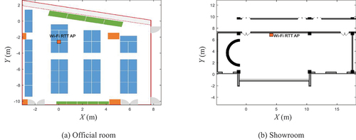
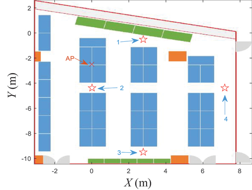
In this section, a series of experiments are designed to verify the accuracy of the proposed algorithms. Two typical indoor environments were selected as the experimental sites. One is a rectangular office; the other one contains an indoor showroom and a corridor. The only used Wi-Fi AP uses an Intel 8260 Wireless card and an Ubuntu 16.04 LTS as hardware and software platforms, which were custom-made by this work. A Google Pixel 1 and a Google Pixel 3 are used as mobile terminals, which support Android P-based Wi-Fi FTM and can get real-time RTT data from surrounding Wi-Fi APs. In addition, the Google Pixel smartphones contain built-in inertial sensors and magnetometers. The sampling rates of the inertial sensor are 50 Hz for Google Pixel 1 and 100 Hz for Google Pixel 3. The Wi-Fi FTM sampling rate of both mobile phones is 10 Hz. The Wi-Fi AP is fixed on the stands with a 1.5 m height in the testing rooms, which contains NLOS and multipath propagation effects such as glasses, partition shades, and wall columns. The tester is almost walking within the coverage of the testing Wi-Fi AP, ensuring that the RTT data could be always received. The testing rooms and the AP positions are shown in . The ground-truth positions on the trajectories are measured beforehand and labeled on the ground. The sequence in which the tester passes through the ground-truth points is preplanned. Each time the tester passes a ground-truth point, he/she will click the button set on the smartphone screen, and the data collection program running on the smartphone will record the corresponding time. In this way, we get the location and timestamp of each passed ground-truth point, which is used to evaluate the testing accuracy.
Figure 2. Maps of the experimental scenes.
6.1. PDR evaluation
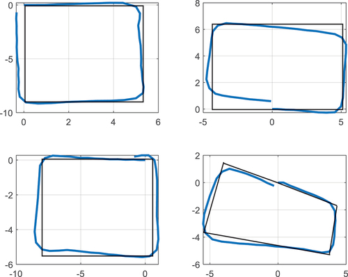
To evaluate the adopted PDR algorithm, in this article, only the handheld message mode is considered and only the normal walking mode is considered. The rectangular testing trajectories are sampled using the Google Pixel 1 in the experimental site shown in which contains magnetic interference. We only evaluate the short-term accuracy of PDR in this part, and the long-term accuracy will be evaluated in later experiments.
shows the step detection results of the adopted peak detection-based step detector. It can be seen that every detected peak point lies on the biggest acceleration point in each step cycle. The estimated results are shown in . The end-to-end positioning errors are 0.763 m, 0.598 m, 0.877 m, and 0.378 m, respectively. The short-term sub-meter accuracy means a potential ability to provide a good constraint for the initial position estimation.
Figure 3. Step detection results.
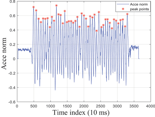
Figure 4. Short-term PDR results.
6.2. Accuracy evaluation of the initial position
To evaluate the proposed initial position determination algorithm by single AP and smartphone, we set up four groups of experiments. The testing starting positions relative to the AP are 3.41 m, 1.88 m, 7.53 m, and 7.42 m, respectively. Two groups are closer to the AP, and the other two groups are a little far away from the AP. The four starting points are shown in .
Figure 5. Four testing initial positions.
As the tester starts to walk, the algorithm will use the generated step lengths, headings, and received ranging information to estimate the starting position. shows the variation trend of the initial position errors for the four experiments with the increase in the number of steps. We can see that the errors of trajectories 3 and 4 are converged to less than 4 m, while the steps surpass 10 steps and converge to 2.7 m and 3.1 m, with the steps exceeding 35 steps. We can also see a trend from the initial positioning results that the farther the starting position from the AP is, the more steps it takes to converge.
Figure 6. Testing results of four initial positions.
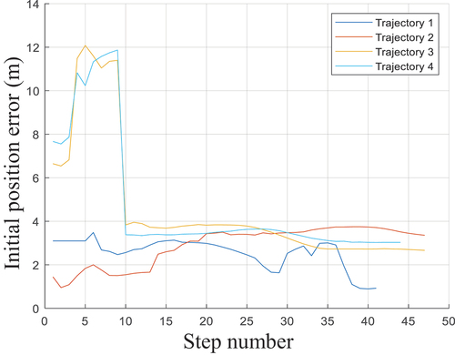
This may be caused by two reasons. One reason is that the initialized value of the initial position is the AP’s position. Thus, for the initial position closer to the AP, the set initial value is closer to the ground truth. Hence, it needs fewer steps to converge. Another reason may lie in the ranging accuracy of the AP. As the distance increases, NLOS and multipath effects will also increase, resulting in reduced ranging accuracy. The uncertainty of ranging accuracy may lead to more information required to converge. There is an opposite trend for trajectory 2 compared to the other three trajectories. As the number of steps increases, its initial position error also tends to increase slowly. This is caused by that the ground-truth position is very close to the AP, hence the set initial value for the initial position is close to the ground truth. However, as the step number increases, the distance from AP is also increasing and the ranging error may also increase. Moreover, the accuracy of PDR will also decrease as the walking distance increases. Hence, for the case where the initial Wi-Fi range is less than a certain threshold, such as 3 m, only the first three to four steps are used to estimate the initial position.
The overall initial positioning accuracy lies in 3 m to 4 m in our experiment. This accuracy has reached the level of conventional Wi-Fi positioning. This shows that our proposed algorithm for initial position determination based on one single AP and PDR is effective.
6.3. Accuracy evaluation of PDR and single Wi-Fi AP integration
Wi-Fi FTM ranging and RSSI ranging are sensitive to different types of interference. For instance, Wi-Fi FTM is mainly affected by NLOS and random errors, while RSSI is objected to multipath propagation and is more accurate for short distances (Yu et al. Citation2020a). PDR is not disturbed by ranging-based noise but suffered from measurement errors of sensors. Hence, the proposed fusion algorithm can overcome the shortcomings of each.
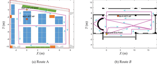
To evaluate our proposed positioning algorithms, two experiments are carried out. Route A is conducted in an official room shown in , containing 469 steps. Another route B is carried out in a showroom shown in and contains 802 steps. The initial position is provided by the proposed LM-based initial position estimation algorithm. The first three steps are used to find the initial position for route A, while the first 15 steps are used for route B. The evaluation points are approximately evenly distributed on the routes.
Figure 7. Two experimental routes in the two indoor scenes.
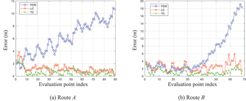
shows the comparison of the trajectories estimated by the proposed original PDR, LC, and TC methods. The results show that the trajectories estimated by LC and TC algorithms are constrained within a certain range, while the original PDR drifts as the time increases. A detailed comparison of errors can be obtained from It can also be found that the estimated results of TC integration are better than that of LC integration overall.
Figure 8. Comparison of the trajectories estimated by the original PDR, LC, and TC methods.
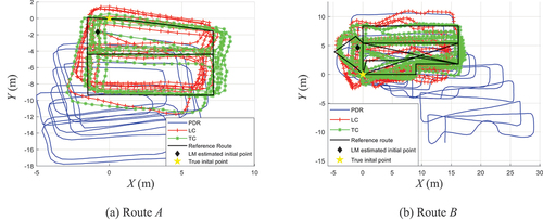
Figure 9. Comparison of the errors in each evaluation.
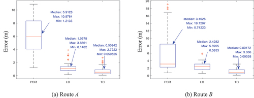
demonstrates that for route A, the error of LC integration ranges from 0.14 m to 3.89 m and the median error is 1.07 m, and the error of TC integration ranges from 0.05 m to 2.72 m and the median error is 0.51 m. For route B, the error of LC integration ranges from 0.59 m to 5.90 m and the median error is 2.43 m. And the error of TC integration ranges from 0.10 m to 3.09 m and the median error is 0.80 m. The median error of TC integration has decreased by more than 52% and 67%, respectively, compared to that of LC integration.
Figure 10. Comparison of the statistical errors.
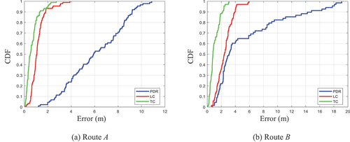
The CDF errors are shown in . It can also be found that the accuracy of the proposed TC integration is significantly improved compared to the LC integration in both experiments. The 90% error of TC integration is less than 1.36 m and 2.23 m for routes A and B, respectively, compared to that of LC integration, which is less than 1.82 m and 3.98 m, respectively. The RMS error of TC integration is 0.87 m and 1.28 m for routes A and B, respectively, compared to that of LC integration, which is 1.32 m and 2.72 m, respectively, and the corresponding improvement is more than 34% and 52%. Compared with the state-of-the-art UPF-based LC integrated positioning algorithm based on multiple Wi-Fi FTM APs proposed by Yu et al. (Citation2020a), our algorithm obtains a similar accuracy within the coverage of one single AP.
Figure 11. Comparison of the CDF errors.
Interestingly, we found that even if the initial position is not relatively accurate, the proposed fusion algorithm can gradually correct the trajectory. In addition, we found an anomaly, that is, the accuracy of the initial position estimation of route B is low, but the accuracy of the PDR for the first period is quite high. After our analysis, it was found that this was due to a misalignment deviation in the headings of the initial 15 steps, causing the PDR to accidentally drift to a more precise position. This is just an occasional event. It can still be seen that the position of the PDR will still increase over time.
7. Conclusions
To solve the smartphone-based indoor positioning problem in the case under one single Wi-Fi FTM AP, this article has done the following work. 1) We use the PDR and Wi-Fi FTM and RSSI ranging values measured during the initial period to estimate the initial position by an LM algorithm. 2) A TC integration algorithm combining Wi-Fi RTT, RSSI, and PDR is proposed. The errors of step length and step heading are used as the error state-vector of PDR, which is more concise and more practical for PDR. 3) We also detailed the adopted PDR algorithm, especially the step detection algorithm, and the LC integration model used in this article. Comprehensive experiments are conducted to evaluate our proposed systems, and the results prove the corresponding effectiveness.
This article concludes with a brief discussion of future work. Although our proposed system is based on the assumption that only one Wi-Fi FTM AP is acquired, it can be easily extended to multiple APs cases. In addition to this article, the TC integration has been proven to be more accurate than LC integration by many works. In the future, other observations extracted from one single Wi-Fi AP, such as Angle of Arrival (AOA) and Channel State Information (CSI) that can provide accurate angle measurement information, can be tightly integrated with PDR and ranging signals to achieve a more accurate and powerful indoor positioning system.
Disclosure statement
No potential conflict of interest was reported by the authors.
Data availability statement
The data and materials that support the findings of this study are freely available upon request from the corresponding author (corresponding author’s e-mail: [email protected]).
Additional information
Funding
Notes on contributors
Yuan Wu
Yuan Wu is pursuing his doctoral degree at Wuhan University. His research interests include indoor/outdoor seamless positioning/navigation, data-driven-based positioning perception, and multi-sensors fusion.
Ruizhi Chen
Ruizhi Chen is a professor and director of the State Key Laboratory of Surveying, Mapping and Remote Sensing Information Engineering, Wuhan University, and an academician of the Finnish Academy of Sciences and Humanities. He is an internationally renowned scholar in the field of navigation and positioning. He is committed to the theoretical research and core technology development of smartphone indoor and outdoor seamless navigation and positioning and low-orbit satellite navigation enhancement.
Wenju Fu
Wenju Fu is a Postdoc researcher at Wuhan University. His research interests include GNSS data processing and LEO orbit determination.
Wei Li
Wei Li is pursuing his doctoral degree at Wuhan University. His research interests include indoor positioning/navigation and millimeter-wave radar positioning.
Haitao Zhou
Haitao Zhou is a PhD candidate at Wuhan University. His research interests include surveying data processing and GNSS precise positioning.
Guangyi Guo
Guangyi Guo is a Postdoc researcher at Wuhan University. His research interests include indoor positioning, acoustic localization, and mobility context computing.
References
- Al-Qaness, M.A.A. 2019. “Device-Free Human Micro-Activity Recognition Method Using WiFi Signals.” Geo-Spatial Information Science 22 (2): 128–137. doi:10.1080/10095020.2019.1612600.
- Bahillo, A., S. Mazuelas, R.M. Lorenzo, P. Fernández, J. Prieto, R.J. Durán, and E.J. Abril. 2010. “Accurate and Integrated Localization System for Indoor Environments Based on IEEE 802.11 Round-Trip Time Measurements.” Journal on Wireless Communications and Networking 2010 (1): 112. doi:10.1155/2010/102095.
- Bai, N., Y. Tian, Y. Liu, Z.X. Yuan, Z.L. Xiao, and J. Zhou. 2020. “A High-Precision and Low-Cost IMU-Based Indoor Pedestrian Positioning Technique.” IEEE Sensors Journal 20 (12): 6716–6726. doi:10.1109/JSEN.2020.2976102.
- Banin, L., O. Bar-Shalom, N. Dvorecki, and Y. Amizur. 2019. “Scalable Wi-Fi Client Self-Positioning Using Cooperative FTM-Sensors.” IEEE Transactions on Instrumentation and Measurement 68 (10): 3686–3698. doi:10.1109/TIM.2018.2880887.
- Bullmann, M., T. Fetzer, F. Ebner, M. Ebner, F. Deinzer, and M. Grzegorzek. 2020. “Comparison of 2.4 GHz WiFi FTM- and RSSI-Based Indoor Positioning Methods in Realistic Scenarios.” Sensors 20 (16): 4515. doi:10.3390/s20164515.
- Cao, Z.P., Y.F. Cheng, R.Z. Chen, G.Y. Guo, F. Ye, L. Chen, and Y.J. Pan. 2019. “An Infant Monitoring System with the Support of Accurate Real-Time Indoor Positioning.” Geo-Spatial Information Science 22 (4): 279–289. doi:10.1080/10095020.2019.1631617.
- Chen, R.Z., L. Pei, and Y.W. Chen. 2011. “A Smart Phone Based Pdr Solution for Indoor Navigation.” Proceedings of the 24th international Technical Meeting of the Satellite Division of the Institute of Navigation 10 (1): 1404–1408.
- Chen, L.H., E.H.K. Wu, M.H. Jin, and G.H. Chen. 2014. “Intelligent Fusion of Wi-Fi and Inertial Sensor-Based Positioning Systems for Indoor Pedestrian Navigation.” IEEE Sensors Journal 14 (11): 4034–4042. doi:10.1109/JSEN.2014.2330573.
- Chen, R.Z., and L. Chen. 2021. Urban Informatics : Smartphone-Based Indoor Positioning Technologies. Singapore: Springer.
- Chen, R.Z., Z. Li, F. Ye, G.Y. Guo, S.H. Xu, L. Qian, Z.Y. Liu, and L.X. Huang. 2021. “Precise Indoor Positioning Based on Acoustic Ranging in Smartphone.” IEEE Transactions on Instrumentation and Measurement 70: 1–712. doi:10.1109/TIM.2021.3082269.
- Choi, J., and Y.S. Choi. 2021. “Calibration-Free Positioning Technique Using Wi-Fi Ranging and Built-In Sensors of Mobile Devices.” IEEE Internet of Things Journal 8 (1): 541–554. doi:10.1109/JIOT.2020.3004774.
- Correa, A., M.B. Llado, A. Morell, and J.L. Vicario. 2016. “Indoor Pedestrian Tracking by On-Body Multiple Receivers.” IEEE Sensors Journal 16 (8): 2545–2553. doi:10.1109/JSEN.2016.2518872.
- Dai, H., W.H. Ying, and J. Xu. 2016. “Multi-Layer Neural Network for Received Signal Strength-Based Indoor Localization.” IET Communications 10 (6): 717–723. doi:10.1049/iet-com.2015.0469.
- Dalla Torre, A., P. Gallo, D. Gubiani, C. Marshall, A. Montanari, F. Pittino, and A. Viel. 2019. “A Map-Matching Algorithm Dealing with Sparse Cellular Fingerprint Observations.” Geo-Spatial Information Science 22 (2): 89–106. doi:10.1080/10095020.2019.1616933.
- Deng, Z.A., Y. Hu, J.G. Yu, and Z.Y. Na. 2015. “Extended Kalman Filter for Real Time Indoor Localization by Fusing WiFi and Smartphone Inertial Sensors.” Micromachines 6 (4): 523–543. doi:10.3390/mi6040523.
- Dvorecki, N., O. Bar-Shalom, and Y. Amizur. 2019. ”A Machine Learning Approach for Wi-Fi Rtt Ranging.” In Proceedings of the 2019 international technical meeting of the institute of navigation, 435–444. Institute of Navigation.
- Ge, H.B., B.F. Li, S. Jia, L.W. Nie, T.H. Wu, Z. Yang, J.Z. Shang, Y.N. Zheng, and M.R. Ge. 2022. “Leo Enhanced Global Navigation Satellite System (Legnss): Progress, Opportunities, and Challenges.” Geo-Spatial Information Science 25 (1): 1–13. doi:10.1080/10095020.2021.1978277.
- Gu, F.Q., X.K. Hu, M. Ramezani, D. Acharya, K. Khoshelham, S. Valaee, and J. Shang. 2019a. “Indoor Localization Improved by Spatial Context—a Survey.” ACM Computing Surveys 52 (3): 1–35. doi:10.1145/3322241.
- Gu, F.Q., K. Khoshelham, C.Y. Yu, and J. Shang. 2019b. “Accurate Step Length Estimation for Pedestrian Dead Reckoning Localization Using Stacked Autoencoders.” IEEE Transactions on Instrumentation and Measurement 68 (8): 2705–2713. doi:10.1109/TIM.2018.2871808.
- Harle, R. 2013. “A Survey of Indoor Inertial Positioning Systems for Pedestrians.” IEEE Communications Surveys & Tutorials 15 (3): 1281–1293. doi:10.1109/SURV.2012.121912.00075.
- Hoang, M.T., B. Yuen, X.D. Dong, T. Lu, R. Westendorp, and K. Reddy. 2019. “Recurrent Neural Networks for Accurate RSSI Indoor Localization.” IEEE Internet of Things Journal 6 (6): 10639–10651. doi:10.1109/JIOT.2019.2940368.
- Hsu, Y.L., J.S. Wang, and C.W. Chang. 2017. “A Wearable Inertial Pedestrian Navigation System with Quaternion-Based Extended Kalman Filter for Pedestrian Localization.” IEEE Sensors Journal 17 (10): 3193–3206. doi:10.1109/JSEN.2017.2679138.
- Huang, L., B.G. Yu, H.S. Li, H. Zhang, S. Li, R.Z. Zhu, and Y.N. Li. 2020. “HPIPS: A High-Precision Indoor Pedestrian Positioning System Fusing WiFi-RTT, MEMS, and Map Information.” Sensors 20 (23): 6795. doi:10.3390/s20236795.
- Ibrahim, M., H. Liu, M. Jawahar, V. Nguyen, M. Gruteser, R. Howard, B. Yu, and F. Bai. 2018. “Verification: Accuracy Evaluation of WiFi Fine Time Measurements on an Open Platform.” Proceedings of the 24th Annual International Conference on Mobile Computing and Networking, 417–427. doi:10.1145/3241539.3241555.
- Kang, W., and Y. Han. 2015. “SmartPdr: Smartphone-Based Pedestrian Dead Reckoning for Indoor Localization.” IEEE Sensors Journal 15 (5): 2906–2916. doi:10.1109/JSEN.2014.2382568.
- Li, D., B. Zhang, and C. Li. 2016. “A Feature-Scaling-Based K-Nearest Neighbor Algorithm for Indoor Positioning Systems.” IEEE Internet of Things Journal 3 (4): 590–597. doi:10.1109/JIOT.2015.2495229.
- Li, Y., Y. Zhuang, P. Zhang, H.Y. Lan, X.J. Niu, and N. El-Sheimy. 2017. “An Improved Inertial/wifi/magnetic Fusion Structure for Indoor Navigation.” Information Fusion 34 (1): 101–119. doi:10.1016/j.inffus.2016.06.004.
- Li, Z., X.H. Zhao, F.Y. Hu, Z.L. Zhao, J.L.C. Villacres, and T. Braun. 2019. “SoiCp: A Seamless Outdoor–indoor Crowdsensing Positioning System.” IEEE Internet of Things Journal 6 (5): 8626–8644. doi:10.1109/JIOT.2019.2921561.
- Li, M., J.Y. Qin, D.R. Li, R.Z. Chen, X. Liao, and B.X. Guo. 2021. “VNLSTM-PoseNet: A Novel Deep ConvNet for Real-Time 6-DOF Camera Relocalization in Urban Streets.” Geo-Spatial Information Science 24 (3): 422–437. doi:10.1080/10095020.2021.1960779.
- Li, Y., Y. Zhuang, X. Hu, Z.Z. Gao, J.H. Hu, L. Chen, Z. He, et al. 2021. ”Toward Location-Enabled IoT (LE-IoT): IoT Positioning Techniques, Error Sources, and Error Mitigation.” IEEE Internet of Things Journal 8 (6): 4035–4062. doi:10.1109/JIOT.2020.3019199.
- Lin, S.L., and W.W.S. Hui. 2016. “Improved Pedestrian Dead-Reckoning-Based Indoor Positioning by RSSI-Based Heading Correction.” IEEE Sensors Journal 16 (21): 7762–7773. doi:10.1109/JSEN.2016.2600260.
- Liu, D.H., L. Pei, J.C. Qian, L. Wang, P.L.E. Liu, Z.J. Dong, S.Y. Xie, and W. Wei. 2016. “A Novel Heading Estimation Algorithm for Pedestrian Using a Smartphone Without Attitude Constraints.” The 4th International Conference on Ubiquitous Positioning, Indoor Navigation and Location Based Services (UPINLBS), Shanghai, November 3–4.
- Liu, X., B.D. Zhou, P.P. Huang, W.X. Xue, Q.Q. Li, J.S. Zhu, and L. Qiu. 2021. “Kalman Filter-Based Data Fusion of Wi-Fi RTT and PDR for Indoor Localization.” IEEE Sensors Journal 21 (6): 8479–8490. doi:10.1109/JSEN.2021.3050456.
- Lu, J.Z., K.C. Chen, B.G. Li, and M.M. Dai. 2018. “Hybrid Navigation Method of INS/PDR Based on Action Recognition.” IEEE Sensors Journal 1. doi:10.1109/JSEN.2018.2866521.
- Luo, R.C., and T.J. Hsiao. 2019. “Indoor Localization System Based on Hybrid Wi-Fi/ble and Hierarchical Topological Fingerprinting Approach.” IEEE Transactions on Vehicular Technology 68 (11): 10791–10806. doi:10.1109/TVT.2019.2938893.
- Ma, C.G., B. Wu, S. Poslad, and D.R. Selviah. 2020. “Wi-Fi RTT Ranging Performance Characterization and Positioning System Design.” IEEE Transactions on Mobile Computing 1. doi:10.1109/TMC.2020.3012563.
- Mannay, K., J. Ureña, Á. Hernández, J.M. Villadangos, M. Machhout, and T. Aguili. 2021. “Evaluation of Multi-Sensor Fusion Methods for Ultrasonic Indoor Positioning.” Applied Sciences 11 (15): 6805. doi:10.3390/app11156805.
- Mazuelas, S., A. Bahillo, R.M. Lorenzo, P. Fernandez, F.A. Lago, E. Garcia, J. Blas, and E.J. Abril. 2009. “Robust Indoor Positioning Provided by Real-Time RSSI Values in Unmodified WLAN Networks.” IEEE Journal of Selected Topics in Signal Processing 3 (5): 821–831. doi:10.1109/JSTSP.2009.2029191.
- Nir, D., O. Bar-Shalom, L. Banin, and Y. Amizur. 2019. “A Machine Learning Approach for Wi-Fi RTT Ranging.” Proceedings of the 2019 International Technical Meeting of The Institute of Navigation, 435–444. doi:10.33012/2019.16702
- Poulose, A., O.S. Eyobu, and D.S. Han. 2019. “An Indoor Position-Estimation Algorithm Using Smartphone IMU Sensor Data.” IEEE Access 1. doi:10.1109/ACCESS.2019.2891942.
- Poulose, A., B. Senouci, and D.S. Han. 2019. “Performance Analysis of Sensor Fusion Techniques for Heading Estimation Using Smartphone Sensors.” IEEE Sensors Journal 19 (24): 12369–12380. doi:10.1109/JSEN.2019.2940071.
- Poulose, A., J.H. Kim, and D.S. Han. 2019. “A Sensor Fusion Framework for Indoor Localization Using Smartphone Sensors and Wi-Fi RSSI Measurements.” Applied Sciences 9 (20): 4379. doi:10.3390/app9204379.
- Poulose, A., and D.S. Han. 2020. “Performance Analysis of Fingerprint Matching Algorithms for Indoor Localization.” 2020 International Conference on Artificial Intelligence in Information and Communication (ICAIIC), Fukuoka, Feburary 19–21.
- Qian, J.C., L. Pei, J.B. Ma, R.D. Ying, and P.L. Liu. 2015. “Vector Graph Assisted Pedestrian Dead Reckoning Using an Unconstrained Smartphone.” Sensors 15 (3): 5032–5057. doi:10.3390/s150305032.
- Ruiz, A.R.J., F.S. Granja, J.C.P. Honorato, and J.I.G. Rosas. 2012. “Accurate Pedestrian Indoor Navigation by Tightly Coupling Foot-Mounted IMU and RFID Measurements.” IEEE Transactions on Instrumentation and Measurement 61 (1): 178–189. doi:10.1109/TIM.2011.2159317.
- Seong, J.H., and D.H. Seo. 2020. “Selective Unsupervised Learning-Based Wi-Fi Fingerprint System Using Autoencoder and GAN.” IEEE Internet of Things Journal 7 (3): 1898–1909. doi:10.1109/JIOT.2019.2956986.
- Si, M.H., Y.J. Wang, S.L. Xu, M. Sun, and H.J. Cao. 2020. “A Wi-Fi FTM-Based Indoor Positioning Method with LOS/NLOS Identification.” Applied Sciences 10 (3): 956. doi:10.3390/app10030956.
- Subedi, S., D.H. Kim, B.H. Kim, and J.Y. Pyun. 2021. “Improved Smartphone-Based Indoor Localization System Using Lightweight Fingerprinting and Inertial Sensors.” IEEE Access 9: 53343–53357. doi:10.1109/ACCESS.2021.3070837.
- Sun, M., Y.J. Wang, S.L. Xu, H.X. Qi, and X.X. Hu. 2020. “Indoor Positioning Tightly Coupled Wi-Fi FTM Ranging and PDR Based on the Extended Kalman Filter for Smartphones.” IEEE Access 8: 49671–49684. doi:10.1109/ACCESS.2020.2979186.
- Tian, Q.L., K.I.K. Wang, and Z. Salcic. 2019. “A Low-Cost INS and UWB Fusion Pedestrian Tracking System.” IEEE Sensors Journal 19 (10): 3733–3740. doi:10.1109/JSEN.2019.2894714.
- Wu, Y., H.B. Zhu, Q.X. Du, and S.M. Tang. 2019a. “A Pedestrian Dead-Reckoning System for Walking and Marking Time Mixed Movement Using an Shss Scheme and a Foot-Mounted IMU.” IEEE Sensors Journal 19 (5): 1661–1671. doi:10.1109/JSEN.2018.2884834.
- Wu, Y., H.B. Zhu, Q.X. Du, and S.M. Tang. 2019b. “A Survey of the Research Status of Pedestrian Dead Reckoning Systems Based on Inertial Sensors.” International Journal of Automation and Computing 16 (1): 65–83. doi:10.1007/s11633-018-1150-y.
- Wu, Y., R.Z. Chen, W. Li, Y. Yu, H.T. Zhou, and K. Yan. 2021. “Indoor Positioning Based on Walking-Surveyed Wi-Fi Fingerprint and Corner Reference Trajectory-Geomagnetic Database.” IEEE Sensors Journal 21 (17): 18964–18977. doi:10.1109/JSEN.2021.3086485.
- Xu, L.M., Z. Xiong, J.Y. Liu, Z.C. Wang, and Y.M. Ding. 2019. “A Novel Pedestrian Dead Reckoning Algorithm for Multi-Mode Recognition Based on Smartphones.” Remote Sensing 11 (3): 294. doi:10.3390/rs11030294.
- Xu, S.H., R.Z. Chen, Y.Y. Yu, G.Y. Guo, and L.X. Huang. 2019. “Locating Smartphones Indoors Using Built-In Sensors and Wi-Fi Ranging with an Enhanced Particle Filter.” IEEE Access 7: 95140–95153. doi:10.1109/ACCESS.2019.2927387.
- Yu, Y., R.Z. Chen, L. Chen, G.Y. Guo, F. Ye, and Z.Y. Liu. 2019. “A Robust Dead Reckoning Algorithm Based on Wi-Fi FTM and Multiple Sensors.” Remote Sensing 11 (5): 504. doi:10.3390/rs11050504.
- Yu, Y., R.Z. Chen, L. Chen, S.H. Xu, W. Li, Y. Wu, and H.T. Zhou. 2020a. “Precise 3-D Indoor Localization Based on Wi-Fi FTM and Built-In Sensors.” IEEE Internet of Things Journal 7 (12): 11753–11765. doi:10.1109/JIOT.2020.2999626.
- Yu, Y., R.Z. Chen, Z.Y. Liu, G.Y. Guo, F. Ye, and L. Chen. 2020b. “Wi-Fi Fine Time Measurement: Data Analysis and Processing for Indoor Localisation.” Journal of Navigation 73 (5): 1106–1128. doi:10.1017/S0373463320000193.
- Zafari, F., A. Gkelias, and K.K. Leung. 2019. “A Survey of Indoor Localization Systems and Technologies.” IEEE Communications Surveys & Tutorials 21 (3): 2568–2599. doi:10.1109/COMST.2019.2911558.
- Zhang, P., R.Z. Chen, Y. Li, X.J. Niu, L. Wang, M. Li, and Y.J. Pan. 2018. “A Localization Database Establishment Method Based on Crowdsourcing Inertial Sensor Data and Quality Assessment Criteria.” IEEE Internet of Things Journal 5 (6): 4764–4777. doi:10.1109/JIOT.2018.2817599.
- Zhuang, Y., and N. El-Sheimy. 2016. “Tightly-Coupled Integration of WiFi and MEMS Sensors on Handheld Devices for Indoor Pedestrian Navigation.” IEEE Sensors Journal 16 (1): 224–234. doi:10.1109/JSEN.2015.2477444.